CMS 50 and CMS 65 controls
1 HI-PASS FILTER
The HI-PASS FILTER rotative switch permits to activate or not the 12dB/octave high-pass filter.
We advise you to set the rotative switch on FULL RANGE (deactivate the high-pass filter) in the
case of a use in stereo configuration (2.0). We advise you to use the positions 45, 60 or 90Hz
in the case of a use of the system with one or several subwoofers.
2 LF SHELVING
The LF SHELVING rotative switch permits to activate or not a correction of the sound level
under 450Hz. We advise you to set the LF SHELVING rotative switch on +2dB when the pre-
mises acoustics naturally softens that frequency range. We advise you to set the LF SHELVING
rotative switch on FLAT when the premises acoustics is neutral. We advise you to set the LF
SHELVING rotative switch on –2, -4, or –6dB when the loudspeakers are placed next to a wall
or an angle.
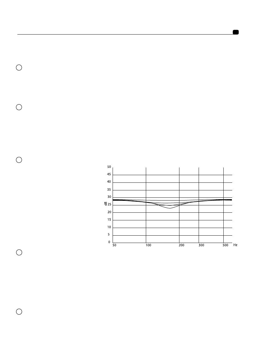
3 DESKTOP NOTCH
The DESKTOP NOTCH rotative
switch permits to activate or not
a correction of the sound level at
a central frequency of 160Hz for
a Q factor of 2. We advise you to
set the rotative switch on –2, -4 or
–6dB when the loudspeakers are
positioned on a table, a console
or any other support that creates
reflections.
CMS
User Manual
7
4 HF SHELVING
The HF SHELVING rotative switch permits to activate or not a correction of the sound level
from 4.5 kHz. We advise you to set it on:
• +2dB when the premises acoustics naturally softens this frequency range (mat environ-
ment).
• - FLAT when the premises acoustics is neutral.
• –2 or –4dB when the premises acoustics naturally increases this frequency range (brilliant
environment)
5 INPUT LEVEL
The INPUT LEVEL rotative switch function is to make the output sensitivity of the mixing conso-
le, or any other source, correspond to the input sensitivity of the loudspeakers. The available
sensitivities are +4dBu, 0, -10dBv. The +4dBu position corresponds to the professional stan-
dard. The -10dBv corresponds to the general public standard. The 0 position is an interme-
diate position.