Johnson Controls PCG4A24 Installation guide

Category
Heat pumps
Type
Installation guide

This manual is also suitable for

Johnson Controls Unitary Products 1183746-UIM-D-1015
®
SINGLE PACKAGE
AIR CONDITIONER/GAS HEAT
MODELS: PCG4 Series
(2-5 Ton)
INSTALLATION MANUAL
LIST OF SECTIONS
GENERAL INFORMATION . . . . . . . . . . . . . . . . . . . . . . . . . . . . . . . . 1
SAFETY . . . . . . . . . . . . . . . . . . . . . . . . . . . . . . . . . . . . . . . . . . . . . . . 1
MODEL NUMBER NOMENCLATURE . . . . . . . . . . . . . . . . . . . . . . . 2
INSTALLATION . . . . . . . . . . . . . . . . . . . . . . . . . . . . . . . . . . . . . . . . . 2
AIRFLOW PERFORMANCE . . . . . . . . . . . . . . . . . . . . . . . . . . . . . .11
OPERATION . . . . . . . . . . . . . . . . . . . . . . . . . . . . . . . . . . . . . . . . . .15
TYPICAL WIRING DIAGRAMS . . . . . . . . . . . . . . . . . . . . . . . . . . . .19
START UP SHEET . . . . . . . . . . . . . . . . . . . . . . . . . . . . . . . . . . . . . .25
LIST OF FIGURES
Component Location . . . . . . . . . . . . . . . . . . . . . . . . . . . . . . . . . . . . . 3
Center of Gravity Location . . . . . . . . . . . . . . . . . . . . . . . . . . . . . . . . . 4
Unit Dimensions . . . . . . . . . . . . . . . . . . . . . . . . . . . . . . . . . . . . . . . . . 5
Bottom Duct Dimensions (inches) . . . . . . . . . . . . . . . . . . . . . . . . . . . 6
Rear Duct Dimensions (inches) . . . . . . . . . . . . . . . . . . . . . . . . . . . . . 6
Typical Field Control Wiring Diagram For Gas Heat - AC Models . . . 7
Typical Field Power Wiring Diagram . . . . . . . . . . . . . . . . . . . . . . . . . 7
Flue Vent Outlet Air Hood . . . . . . . . . . . . . . . . . . . . . . . . . . . . . . . . 10
Gas Valve . . . . . . . . . . . . . . . . . . . . . . . . . . . . . . . . . . . . . . . . . . . . .17
Measuring External Static Pressure . . . . . . . . . . . . . . . . . . . . . . . . .18
Connection Wiring Diagram - 2 to 3 Ton Models . . . . . . . . . . . . . . .19
Ladder Wiring Diagram - 2 to 3 Ton Models . . . . . . . . . . . . . . . . . . .20
Connection Wiring Diagram - 3.5 to 5 Ton Models . . . . . . . . . . . . . .21
Ladder Wiring Diagram - 3.5 to 5 Ton Models . . . . . . . . . . . . . . . . .22
R-410A Quick Reference Guide . . . . . . . . . . . . . . . . . . . . . . . . . . . .23
LIST OF TABLES
Unit Limitations . . . . . . . . . . . . . . . . . . . . . . . . . . . . . . . . . . . . . . . . . . 3
Weights and Dimensions . . . . . . . . . . . . . . . . . . . . . . . . . . . . . . . . . . 4
Unit Dimensions . . . . . . . . . . . . . . . . . . . . . . . . . . . . . . . . . . . . . . . . . 5
Unit Clearances . . . . . . . . . . . . . . . . . . . . . . . . . . . . . . . . . . . . . . . . . 5
Electrical Data . . . . . . . . . . . . . . . . . . . . . . . . . . . . . . . . . . . . . . . . . . 7
Physical Data . . . . . . . . . . . . . . . . . . . . . . . . . . . . . . . . . . . . . . . . . . . 8
Natural Gas Pipe Sizing Chart . . . . . . . . . . . . . . . . . . . . . . . . . . . . . . 9
Propane (LP) Gas Pipe Sizing Chart . . . . . . . . . . . . . . . . . . . . . . . . . 9
Natural Gas Application Data . . . . . . . . . . . . . . . . . . . . . . . . . . . . . .10
Propane (LP) Gas Application Data . . . . . . . . . . . . . . . . . . . . . . . . .10
Airflow - Side Duct Application . . . . . . . . . . . . . . . . . . . . . . . . . . . . .11
Airflow - Bottom Duct Application . . . . . . . . . . . . . . . . . . . . . . . . . . .13
Additional Static Resistance . . . . . . . . . . . . . . . . . . . . . . . . . . . . . . .15
Ignition Control Board Flash Codes . . . . . . . . . . . . . . . . . . . . . . . . .16
Gas Rate Cubic Feet Per Hour . . . . . . . . . . . . . . . . . . . . . . . . . . . . .18
SECTION I: GENERAL INFORMATION
These are electric cooling/gas heating units designed for outdoor instal-
lation. Only gas piping, electric power and duct connections are
required at the point of installation.
The gas-fired heaters have spark ignition.
The refrigerant system is fully charged with R-410A Refrigerant, and is
tested and factory sealed.
SECTION II: SAFETY
This is a safety alert symbol. When you see this symbol on
labels or in manuals, be alert to the potential for personal
injury.
Understand and pay particular attention to the signal words DANGER,
WARNING, or CAUTION.
DANGER indicates an imminently hazardous situation, which, if not
avoided, will result in death or serious injury.
WARNING indicates a potentially hazardous situation, which, if not
avoided, could result in death or serious injury.
CAUTION indicates a potentially hazardous situation, which, if not
avoided may result in minor or moderate injury. It is also used to
alert against unsafe practices and hazards involving only property dam-
age.
WARNING
Improper installation may create a condition where the operation of
the product could cause personal injury or property damage.
Improper installation, adjustment, alteration, service or maintenance
can cause injury or property damage. Failure to carefully read and
follow all instructions in this manual can result in furnace mal-
function, death, personal injury and/or property damage. Only a
qualified contractor, installer or service agency should install this
product.
CAUTION
This product must be installed in strict compliance with the installa-
tion instructions and any applicable local, state, and national codes
including, but not limited to building, electrical, and mechanical
codes.
!
!
1183746-UIM-D-1015
2 Johnson Controls Unitary Products
Due to system pressure, moving parts, and electrical components,
installation and servicing of air conditioning equipment can be hazard-
ous. Only qualified, trained service personnel should install, repair, or
service this equipment. Untrained personnel can perform basic mainte-
nance functions of cleaning coils and filters and replacing filters.
Observe all precautions in the literature, labels, and tags accompanying
the equipment whenever working on air conditioning equipment. Be
sure to follow all other applicable safety precautions and codes includ-
ing ANSI Z223.1 or CSA-B149.1- latest edition.
Wear safety glasses and work gloves. Use quenching cloth and have a
fire extinguisher available during brazing operations.
SECTION III: MODEL NUMBER NOMENCLATURE
SECTION IV: INSTALLATION
INSTALLATION SAFETY INFORMATION
Read these instructions before continuing this appliance installation.
This is an outdoor combination heating and cooling unit. The installer
must assure that these instructions are made available to the consumer
with instructions to retain them for future reference.
1. Refer to the unit rating plate for the approved type of gas for this
product.
2. Install this unit only in a location and position as specified on Page
4 of these instructions.
3. Never test for gas leaks with an open flame. Use commercially
available soap solution made specifically for the detection of leaks
when checking all connections, as specified on Page 10 of these
instructions.
4. Always install unit to operate within the unit's intended temperature-
rise range with the duct system and within the allowable external
static pressure range, as specified on the unit name/rating plate,
specified in Table 6 of these instructions.
5. This equipment is not to be used for temporary heating of buildings
or structures under construction.
WARNING
Before performing service or maintenance operations on unit, turn off
main power switch to unit. Electrical shock could cause personal
injury. Improper installation, adjustment, alteration, service or mainte-
nance can cause injury or property damage. Refer to this manual.
For assistance or additional information consult a qualified installer,
service agency or the gas supplier.
CAUTION
This system uses R-410A Refrigerant which operates at higher pres-
sures than R-22. No other refrigerant may be used in this system.
Gage sets, hoses, refrigerant containers and recovery systems must
be designed to handle R-410A. If you are unsure, consult the equip-
ment manufacturer. Failure to use R-410A compatible servicing
equipment may result in property damage or injury.
!
!
WARNING
If the information in this manual is not followed exactly, a fire or
explosion may result causing property damage, personal injury or
loss of life.
Do not store or use gasoline or other flammable vapors and liquids in
the vicinity of this or any other appliance.
WHAT TO DO IF YOU SMELL GAS:
1. Do not try to light any appliance.
2. Do not touch any electrical switch; do not use any phone in
your building.
3. Immediately call your gas supplier from a neighbor’s phone.
Follow the gas supplier’s instructions.
4. If you cannot reach your gas supplier, call the fire depart-
ment.
Installation and service must be performed by a qualified installer,
service agency or the gas supplier.
!
PCG 4 A 24 50 2 X 1 A
123456789
1. Model Family
PCG - packaged A/C with gas heat,
PHG - packaged heat pump with gas heat,
PCE - packaged A/C with electric heat,
PHE - packaged heat pump with electric heat
5. Gas Heating Input BTU/Hr x 1000
050 = 50,000 BTU/Hr. input, blank = electric heat
6. Voltage-Phase-Frequency
2 = 208/230-1-60, 3=208/230-3-60, 4 = 460-3-60
2. Nominal Cooling Efficiency
4 = 14 SEER, 6 = 16 SEER, etc.
7. NOx Approval
X = low-NOx, blank = not low-Nox
3. Cabinet Size
A = small 35 x 51, B = large 45 x 51
8. Generation Level
1 = first generation
4. Nominal Air Conditioning Cooling Capacity BTUx1000
24 = 24,000 BTU, etc.
9. Revision Level
A = original release, B = second release
Examples:
PCG4B421002X1A is a packaged A/C with gas heat, 14 SEER, 3-1/2 ton, large cabinet, single-stage heat, 100,000 BTU gas heat, 230 volt, single
phase, low-NOx model (first generation, first release)
WARNING
FIRE OR EXPLOSION HAZARD
Failure to follow the safety warning exactly could result in serious
injury, death or property damage.
Never test for gas leaks with an open flame. use a commercially
available soap solution made specifically for the detection of leaks to
check all connections. A fire or explosion may result causing property
damage, personal injury or loss of life.
!
1183746-UIM-D-1015
Johnson Controls Unitary Products 3
LIMITATIONS
These units must be installed in accordance with the following:
In U.S.A.:
1. National Electrical Code, ANSI/NFPA No. 70 - Latest Edition
2. National Fuel Gas Code, ANSI Z223.1 - Latest Edition
3. Gas-Fired Central Furnace Standard, ANSI Z21.47a. - Latest Edi-
tion
4. Local building codes, and
5. Local gas utility requirements
In Canada:
1. Canadian Electrical Code, CSA C22.1
2. Installation Codes, CSA - B149.1.
3. Local plumbing and waste water codes, and
4. Other applicable local codes.
Refer to unit application data found in this document.
After installation, gas fired units must be adjusted to obtain a temperature
rise within the range specified on the unit rating plate.
If components are to be added to a unit to meet local codes, they are to
be installed at the dealer’s and/or customer’s expense.
Size of unit for proposed installation should be based on heat loss/heat
gain calculation made according to the methods of Air Conditioning
Contractors of America (ACCA).
This furnace is not to be used for temporary heating of buildings or
structures under construction.
FIGURE 1: Component Location
FAN MOTOR
OUTDOOR FAN
COIL GUARD PANEL
OUTDOOR COIL
(Behind Panel)
CONTROL BOARD
TRANSFORMER
HIGH VOLTAGE
CONTACTOR
PRESSURE SWITCH
DRAFT INDUCER BLOWER
GAS VALVE
BURNER
ASSEMBLY
GAS HEAT
EXCHANGER
BLOWER MOTOR
TXV
INDOOR COIL
INDOOR BLOWER
COMPRESSOR
REMOVABLE
BASE RAILS
A0297-001
Table 1: Unit Limitations
Model Unit Voltage
Unit Limitations
Applied Voltage Outdoor DB Temp
Min Max Max (°F)
24 208/230-1-60 187 252 125
30 208/230-1-60 187 252 125
36 208/230-1-60 187 252 125
42 208/230-1-60 187 252 125
48 208/230-1-60 187 252 125
60 208/230-1-60 187 252 125
1183746-UIM-D-1015
4 Johnson Controls Unitary Products
LOCATION
Use the following guidelines to select a suitable location for these units:
1. Unit is designed for
outdoor installation only.
2. Condenser coils must have an unlimited supply of air. Where a
choice of location is possible, position the unit on either north or
east side of building.
3. Suitable for mounting on roof curb.
4. For ground level installation, a level pad or slab should be used.
The thickness and size of the pad or slab used should meet local
codes and unit weight. Do not tie the slab to the building foundation.
5. Roof structures must be able to support the weight of the unit and
its options/accessories. Unit must be installed on a solid, level roof
curb or appropriate angle iron frame.
6. Maintain level tolerance to 1/8” across the entire width and length of
unit.
CLEARANCES
All units require particular clearances for proper operation and service.
Installer must make provisions for adequate combustion and ventilation
air in accordance with section 5.3 of Air for Combustion and Ventilation
of the National Fuel Gas Code, ANSI Z223.1 – Latest Edition (in
U.S.A.), or Sections 7.2, 7.3, or 7.4 of Gas Installation Codes, CSA-
B149.1 (in Canada) - Latest Edition, and/or applicable provisions of the
local building codes. Refer to Table 4 for clearances required for com-
bustible construction, servicing, and proper unit operation.
RIGGING AND HANDLING
Exercise care when moving the unit. Do not remove any packaging until
the unit is near the place of installation. Rig the unit by attaching chain
or cable slings to the lifting holes provided in the base rails. Spreader
bars, whose length exceeds the largest dimension across the unit,
MUST be used across the top of the unit.
Units may be moved or lifted with a forklift. Slotted openings in the base
rails are provided for this purpose.
WARNING
Do not attach supply and return duct work to the bottom of the unit
base pan as the drain pan could be compromised.
WARNING
Excessive exposure of this unit to contaminated combustion air may
result in equipment damage or personal injury. Typical contaminates
include: permanent wave solution, chlorinated waxes and cleaners,
chlorine based swimming pool chemicals, water softening chemicals,
carbon tetrachloride, Halogen type refrigerants, cleaning solvents
(e.g. perchloroethylene), printing inks, paint removers, varnishes,
hydrochloric acid, cements and glues, anti-static fabric softeners for
clothes dryers, masonry acid washing materials.
WARNING
Do not permit overhanging structures or shrubs to obstruct con-
denser air discharge outlet, combustion air inlet or vent outlets.
!
!
!
CAUTION
Before lifting, make sure the unit weight is distributed equally on the
rigging cables so it will lift evenly.
CAUTION
If a unit is to be installed on a roof curb other than a Unitary Products
roof curb, gasket or sealant must be applied to all surfaces that come
in contact with the unit underside.
CAUTION
All panels must be secured in place when the unit is lifted.
The condenser coils should be protected from rigging cable damage
with plywood or other suitable material.
FIGURE 2: Center of Gravity Location
!
!
!
X
CENTER OF
GRAVITY
FRONT
OF UNIT
Y
"D"
"C"
"B"
"A"
A0295-001
COMPRESSOR
Table 2: Weights and Dimensions
Model Weight (lbs.) Center of Gravity 4 Point Load Location (lbs.)
Shipping Operating X Y ABCD
24050 372 367 28 15 120 95 81 71
24075 382 377 28 15 124 96 81 76
30050 417 412 28 15 139 99 90 84
30075 421 416 28 15 146 93 82 95
36050 425 420 28 15 141 107 94 78
36075 432 427 28 15 135 115 103 74
36100 436 431 28 15 139 113 99 80
42075 446 441 28 15 145 112 99 85
42100 448 443 28 15 148 110 96 89
48065 520 515 28 15 189 116 93 117
48100 528 523 28 15 169 139 115 100
48125 533 528 28 15 164 145 124 95
60065 537 532 29 15 174 142 124 92
60100 541 536 28 15 177 140 117 102
60125 548 543 27 15 151 167 141 84
1183746-UIM-D-1015
Johnson Controls Unitary Products 5
FIGURE 3: Unit Dimensions
Table 3: Unit Dimensions
Model
Dimensions
ABC
24 51-1/4 35-3/4 47
30 51-1/4 35-3/4 47
36 51-1/4 35-3/4 47
42 51-1/4 35-3/4 49
48 51-1/4 45-3/4 53
60 51-1/4 45-3/4 55
Table 4: Unit Clearances
1,2
1. A 1" clearance must be provided between any combustible material and the supply air duct work.
2. The products of combustion must not be allowed to accumulate within a confined space and recirculate.
Direction Distance (in.) Direction Distance (in.)
Top
3
3. Units must be installed outdoors. Over hanging structure or shrubs should not obstruct condenser air discharge outlet.
36 Power Entry (Right Side) 36
Side Opposite Ducts 36 Left Side 24
Duct Panel 0 Bottom
4
4. Units may be installed on combustible floors made from class A, B or C roof covering materials.
1
HIGH VOLTAGE
CONNECTION 7/8”
HIGH VOLTAGE
CONNECTION 1-3/32”
COMPRESSOR
ACCESS PANEL
CONDENSATE
DRAIN
BLOWER
ACCESS
PANEL
CONTROL ACCESS
PANEL
LOW VOLTAGE CONNECTION
GAS SUPPLY
EXHAUST HOOD
COMBUSTION AIR INTAKE
HEAT EXCHANGER ACCESS PANEL
B
A
C
A0296-001
COIL GUARD
1183746-UIM-D-1015
6 Johnson Controls Unitary Products
DUCTWORK
These units are adaptable to downflow use as well as rear supply and
return air duct openings. To convert to downflow, use the following
steps:
1. Remove the duct covers found in the bottom return and supply air
duct openings.
2. Install the duct covers (removed in step one) to the rear supply and
return air duct openings.
3. Seal duct covers with silicone caulk.
Duct work should be designed and sized according to the methods of
the Air Conditioning Contractors of America (ACCA), as set forth in their
Manual D.
A closed return duct system shall be used. This shall not preclude use
of economizers or ventilation air intake. Flexible joints are recom-
mended to be used in the supply and return duct work to minimize the
transmission of vibration and noise.
Refer to Figures 5 and 6 for information concerning rear and bottom
supply and return air duct openings.
FILTERS
Proper filter size is very important. Filter size, type and pressure drop
should always be considered during duct system design.
Single phase units are shipped without a filter or filter racks. It is the
responsibility of the installer to secure a filter in the return air ductwork
or install a Filter/Frame Kit.
A filter rack and high velocity filters are standard on three phase units.
Filters must always be used and must be kept clean. When filters
become dirt laden, insufficient air will be delivered by the blower,
decreasing your units efficiency and increasing operating costs and
wear-and-tear on the unit and controls.
Filters should be checked monthly; this is especially important since this
unit is used for both heating and cooling.
CONDENSATE DRAIN
A condensate trap must be installed in the condensate drain. The
plumbing must conform to local codes.
DO NOT use Teflon tape or Pipe thread compound.
SERVICE ACCESS
Access to all serviceable components is provided at the following loca-
tions:
Coil guards
Unit top panel
Corner posts
Blower access panel
Control access panel
Indoor coil access panel
Compressor access panel
Heat exchanger access panel
Refer to Figure 4 for location of these access locations and minimum
clearances in Table 4.
Refer to Figure 14 for the R-410A Quick Reference Guide.
Model A B C D E F
24, 30, 36, 42 10 21.5 5 4.5 47.5 32
48, 60 14 13.5 5 3.5 47.5 42
FIGURE 4: Bottom Duct Dimensions (inches)
Model A B
24, 30, 36, 42 9.6 22
48, 60 13.6 14
FIGURE 5: Rear Duct Dimensions (inches)
D
16
C
A
B
A
A0298-001
SUPPLY
AIR DUCT
RETURN
AIR DUCT
F
E
15.6
A
B
A
4.3
A0299-001
6
SUPPLY
AIR DUCT
RETURN
AIR DUCT
NOTICE
Be sure to note supply and return openings.
CAUTION
Hand tighten only.
CAUTION
This system uses R-410A Refrigerant which operates at higher pres-
sures than R-22. No other refrigerant may be used in this system.
Gage sets, hoses, refrigerant containers and recovery systems must
be designed to handle R-410A. If you are unsure, consult the equip-
ment manufacturer. Failure to use R-410A compatible servicing
equipment may result in property damage or injury.
WARNING
Wear safety glasses and gloves when handling refrigerants. Failure
to follow this warning can cause serious personal injury.
!
!
!
1183746-UIM-D-1015
Johnson Controls Unitary Products 7
THERMOSTAT
The room thermostat should be located on an inside wall approximately
60" above the floor where it will not be subject to drafts, sun exposure or
heat from electrical fixtures or appliances. Sealant should be used
behind thermostat to prevent air infiltration. Follow manufacturer's
instructions enclosed with the thermostat for general installation proce-
dure. Color coded insulated wires (minimum #18 AWG) should be used
to connect thermostat to unit. See Figure 6. Do not use power stealing
thermostats.
POWER AND CONTROL WIRING
Field wiring to the unit must conform to provisions of the current N.E.C.
ANSI/NFPA No. 70 or C.E.C. and/or local ordinances. The unit must be
electrically grounded in accordance with local codes or, in their
absence, with the N.E.C./C.E.C. Voltage tolerances which must be
maintained at the compressor terminals during starting and running
conditions are indicated on the unit Rating Plate and Table 1.
The wiring entering the cabinet must be provided with mechanical strain
relief.
A fused disconnect switch should be field provided for the unit. If any of
the wire supplied with the unit must be replaced, replacement wire must
be of the type shown on the wiring diagram.
Electrical service must be sized properly to carry the load. Each unit
must be wired with a separate branch circuit fed directly from the main
distribution panel and properly fused.
Refer to Figures 6 and 7 for typical field wiring and to the appropriate
unit wiring diagram for control circuit and power wiring information.
FIGURE 6: Typical Field Control Wiring Diagram For Gas Heat - AC
Models
FIGURE 7: Typical Field Power Wiring Diagram
THERMOSTAT
NOTE:
Heat Anticipator should be set at 0.35 AMPS for all models
CONTROL
BOARD
Minimum wire size of 18 AWG wire should be used for all field
installed control wiring.
RED
GREEN
YELLOW
WHITE
BLUE
R
G
W
Y
C
A0294-001
CONTACTOR
FIELD SUPPLIED
DISCONNECT
GND
LUG
REFER TO ELECTRICAL
DATA TABLES TO SIZE
THE DISCONNECT
SINGLE
PHASE
POWER
SUPPLY
A0293-001
Table 5: Electrical Data
Model Voltage
Compressor
Outdoor Fan
Motor
Indoor Fan
Blower Motor
MCA
1
(Amps)
1. Minimum Circuit Ampacity.
Max Fuse
2
/
Breaker
3
Size
(Amps)
2. Maximum Over Current Protection per standard UL 1995.
3. Fuse or HACR circuit breaker size installed at factory or field installed.
RLA LRA MCC FLA FLA
24050 208/230-1-60 8.7 45.0 14.4 1.3 2.6 14.8 20
24075 208/230-1-60 8.7 45.0 14.4 1.3 3.8 16.0 20
30050 208/230-1-60 9.8 57.0 15.1 1.3 2.6 16.2 25
30075 208/230-1-60 9.8 57.0 15.1 1.3 3.8 17.4 25
36050, 36075 208/230-1-60 13.0 78.0 23.0 1.3 3.8 21.4 30
36100 208/230-1-60 13.0 78.0 23.0 1.3 5.4 23.0 35
42075, 42100 208/230-1-60 17.9 112.0 28.0 1.3 5.4 29.1 45
48065, 48100, 48125 208/230-1-60 21.8 117.0 34.0 1.7 5.4 34.4 50
60065, 60100, 60125 208/230-1-60 24.4 144.2 38.0 1.7 7.0 39.2 60
1183746-UIM-D-1015
8 Johnson Controls Unitary Products
Table 6: Physical Data
COMPONENT
MODELS
PCG4A24 PCG4A30 PCG4A36 PCG4A42 PCG4B48 PCG4B60
NOMINAL TONNAGE 2.0 2.5 3.0 3.5 4.0 5.0
AHRI Cooling Performance
Gross Capacity @ AHRI A point (MBH) 23.7 30.1 37.2 43.5 47.7 55.0
AHRI net capacity (MBH) 22.8 29.0 34.6 41.0 45.5 52.5
EER 11.0 11.0 11.0 11.0 11.0 11.0
SEER 14.0 14.0 14.0 14.0 14.0 14.0
Nominal CFM 800 1000 1200 1400 1600 2000
System power (KW) 2.1 2.6 3.2 3.8 4.2 4.8
Refrigerant type R410A R410A R410A R410A R410A R410A
Refrigerant charge (lb-oz) 5-4 9-2 8-3 9-4 14-4 14-2
AHRI Gas Heat Performance
Heating model 50 75 50 75 50 75 100 75 100 65 100 125 65 100 125
Heat input (K Btu) 50.0 75.0 50.0 75.0 50.0 75.0 100.0 75.0 100.0 65.0 100.0 125.0 65.0 100.0 125.0
Heat output (K Btu)
40 60 40 60 40 60 80 60 80 52 80 100 52 80 100
AFUE %
81.0 81.0 81.0 81.0 81.0 81.0 81.0 81.0 81.0 81.0 81.0 81.0 81.0 81.0 81.0
No. burners 2 3 2 3 2 3 4 3 4 2 3 4 2 3 4
No. stages 1 1 1 1 1 1 1 1 1 1 1 1 1 1 1
Temperature Rise Range (°F) 40-70 40-70 35-65 40-70 40-70 40-70 40-70
Max. Static Pressure (in. w.c.) 0.5 0.5 0.5 0.5 0.5 0.5
Max. Outlet Air Temp. (°F) 180 180 180 180 180 180
Gas piping connection (in.) 1/2 1/2 1/2 1/2 1/2 1/2
Dimensions (inches)
Length 51-1/4
51-1/4
51-1/4 51-1/4 51-1/4 51-1/4
Width 35-3/4
35-3/4
35-3/4 35-3/4 45-3/4 45-3/4
Height 47 47 47 49 53 55
Operating WT. (lbs.) 359 366 379 386 415 422 426 442 446 495 503 508 522 530 535
Compressors
Type Recip Recip Recip Scroll Scroll Scroll
Condenser Coil Data
Face area (Sq. Ft.) 15.1 17.0 17.0 17.0 23.8 26.0
Rows 2 3 3 3 3 3
Fins per inch 16 16 16 16 16 16
Tube diameter 3/8 3/8 3/8 3/8 3/8 3/8
Circuitry Type Interlaced Interlaced Interlaced Interlaced Interlaced Interlaced
Evaporator Coil Data
Face area (Sq. Ft.) 3.4 3.4 3.4 4.4 4.4 4.4
Rows 2 3 3 3 3 3
Fins per inch 16 16 16 16 16 16
Tube diameter 3/8 3/8 3/8 3/8 3/8 3/8
Circuitry Type Interlaced Interlaced Interlaced Interlaced Interlaced Interlaced
Refrigerant control TXV TXV TXV TXV TXV TXV
Condenser Fan Data
Fan diameter (Inch) 24 24 24 24 26 26
Type Prop Prop Prop Prop Prop Prop
Drive type Direct Direct Direct Direct Direct Direct
No. speeds 1 1 1 1 1 1
Motor HP each 1/4 1/4 1/4 1/4 1/3 1/3
RPM 850 850 850 850 850 850
Nominal total CFM 2400 2400 2400 2400 3200 3200
Direct Drive Evaporator Fan Data
Fan Size (Inch) 11 x 8 11 x 8 11 x 10 11 x 10 11 x 10 11 x 10
Type Centrifugal Centrifugal Centrifugal Centrifugal Centrifugal Centrifugal
Motor HP each 1/3 1/2 1/3 1/2 1/2 3/4 3/4 3/4 1
RPM 1200 Max 1200 Max 1200 Max 1200 Max 1200 Max 1200 Max
Frame size 48 48 48 48 48 48
Filters
Quantity - Size
Field-supplied external filters must be sized so as not to exceed 300 fpm air velocity through disposable
filters. For internal filter use, a filter rack kit is available. Consult the instructions supplied with that kit for
replacement filter sizes. Filter sizes: A=20x20, B=20x30.
1183746-UIM-D-1015
Johnson Controls Unitary Products 9
COMPRESSORS
The compressor used in this product is specifically designed to operate
with R-410A Refrigerant and cannot be interchanged.
The compressor uses polyolester (POE oil), Mobile 3MA POE. This oil
is extremely hydroscopic, meaning it absorbs water readily. POE oil can
absorb 15 times as much water as other oils designed for HCFC and
CFC refrigerants. If refrigerant circuit is opened, take all necessary pre-
cautions to avoid exposure of the oil to the atmosphere.
POE (polyolester) compressor lubricants are known to cause long term
damage to some synthetic roofing materials.
Procedures which risk oil leakage include, but are not limited to, com-
pressor replacement, repairing refrigerant leaks, replacing refrigerant
components such as filter drier, pressure switch, metering device or
coil.
Units are shipped with compressor mountings which are factory-
adjusted and ready for operation.
GAS HEAT
These single stage gas-fired heat sections have direct spark ignition.
GAS PIPING
Proper sizing of gas piping depends on the cubic feet per hour of gas
flow required, specific gravity of the gas and the length of run. National
Fuel Gas Code Z223.1 or CSA B149.1 should be followed in all cases
unless superseded by local codes or gas company requirements. Refer
to Tables 7 and 8.
The BTU content of the gas may differ with locality. The value should be
checked with the local gas utility.
GAS CONNECTION
The gas supply line should be routed through the 1-5/8" hole located on
the right side of the unit. See Figure 3 for the location. The unit is sup-
plied with a rubber grommet that fits in this hole and is used to seal
around the gas pipe. THIS GROMMET MUST BE INSTALLED IN
ORDER TO PREVENT LEAKAGE OF AIR AND WATER INTO THE
HEATING/CONTROLS COMPARTMENT.
Gas piping requirements:
1. A drip leg and a ground joint union must be installed in the gas pip-
ing.
2. When required by local codes, a manual shut-off valve may have to
be installed outside of the unit.
3. Use wrought iron or steel pipe for all gas lines. Pipe thread sealant
should be applied sparingly to male threads only.
4. All piping should be cleaned of dirt and scale by hammering on the
outside of the pipe and blowing out the loose dirt and scale. Before
initial start-up, be sure that all of the gas lines external to the unit
have been purged of air.
CAUTION
This system uses R-410A Refrigerant which operates at higher pres-
sures than R-22. No other refrigerant may be used in this system.
CAUTION
Do not leave the system open to the atmosphere. Unit damage could
occur due to moisture being absorbed by the POE oil in the system.
This type of oil is highly susceptible to moisture absorption
CAUTION
Exposure, even if immediately cleaned up, may cause embrittlement
(leading to cracking) to occur in one year or more. When performing
any service that may risk exposure of compressor oil to the roof, take
precautions to protect roofing.
CAUTION
Do not loosen compressor mounting bolts.
NOTICE
There may be a local gas utility requirement specifying a minimum
diameter for gas piping. All units require a 1/2 inch pipe connection at
the gas valve.
!
!
!
!
Table 7: Natural Gas Pipe Sizing Chart
1
1. Maximum capacity of pipe in cubic feet of gas per hour (based upon a pres-
sure drop of 0.3 inch water column and 0.6 specific gravity gas).
Length
In Feet
Nominal Inches Iron Pipe Size
1/2” 3/4” 1” 1-1/4”
10 132 278 520 1,050
20 92 190 350 730
30 73 152 285 590
40 63 130 245 500
50 56 115 215 440
60 50 105 195 400
70 46 96 180 370
80 43 90 170 350
90 40 84 160 320
100 38 79 150 305
Table 8: Propane (LP) Gas Pipe Sizing Chart
1
1. Maximum capacity of pipe in thousands of BTU per hour (based upon a
pressure drop of 0.5 inch water column).
Length
In Feet
Nominal Inches Iron Pipe Size
1/2” 3/4” 1” 1-1/4”
10 275 567 1071 2,205
20 189 393 732 1496
30 152 315 590 1212
40 129 267 504 1039
50 114 237 448 913
60 103 217 409 834
70 96 196 378 771
80 89 185 346 724
90 83 173 322 677
100 78 162 307 630
CAUTION
If flexible stainless steel tubing is allowed by the authority having
jurisdiction, wrought iron or steel pipe must be installed at the gas
valve and extend a minimum of two (2) inches outside of the unit cas-
ing.
WARNING
Natural gas may contain some propane. Propane being an excellent
solvent, will quickly dissolve white lead or most standard commercial
compounds. Therefore, a special pipe thread sealant must be
applied when wrought iron or steel pipe is used. Shellac base com-
pounds such as gaskoloc or stalastic, and compounds such as Rec-
torseal # 5, Clyde’s or John Crane may be used.
!
!
1183746-UIM-D-1015
10 Johnson Controls Unitary Products
5. The gas supply should be a separate line and installed in accor-
dance with all applicable safety codes. After the gas connections
have been completed, open the main shut-off valve admitting nor-
mal gas pressure to the gas valve. Check all joints for leaks with
soap solution or other material suitable for the purpose. NEVER
USE AN OPEN FLAME.
6. The unit and its equipment shutoff valve must be disconnected from
the gas supply system during and pressure testing of that system at
test pressures in excess of 1/2 psi (3.48 kPA)
7. The unit must be isolated from the gas supply piping system by
closing its individual manual shut-off valve before conducting any
pressure testing of the gas supply piping system at test pressures
equal to or less than 1/2 psig (3.48 kPA).
FLUE VENT AND AIR INTAKE HOOD
The flue vent hood and air intake hoods are shipped loose. These hoods
must be installed to assure proper unit operation. The hoods must be fas-
tened to the outside of the side gas control/electrical compartment with
the screws provided. See Figure 8.
WARNING
FIRE OR EXPLOSION HAZARD
Failure to follow the safety warning exactly could result in serious
injury, death or property damage.
Never test for gas leaks with an open flame. use a commercially
available soap solution made specifically for the detection of leaks to
check all connections. A fire or explosion may result causing property
damage, personal injury or loss of life.
!
WARNING
Flue hood surfaces may be hot.
FIGURE 8: Flue Vent Outlet Air Hood
CAUTION
The flue exhaust hood must be properly installed and within the rec-
ommended clearances. Further communications and action must be
given to the home or building owner(s) to eliminate any unauthorized
human contact around this area during the heating cycle. Flue hood
surfaces and the immediate area reach high temperatures during the
heating cycle.
!
New Graphic to be added later
AIR INTAKE HOOD
AIR INTAKE SCREEN
EXHAUST HOOD
A0284-001
!
Table 9: Natural Gas Application Data
Available On Models
Input (MBH)
1
High Fire
1. Heating capacity valid for elevations up to 2000 feet above sea level. For elevations above 2,000 feet, rated capacity should be reduced by 4% for each 1,000 feet
above sea level.
Output (MBH)
High Fire
Gas Rate
2
Ft.
3
/Hr.
High Fire/Low Fire
2. Based on 1075 BTU/Ft.
3
.
Number of
Burners
Temp. Rise ºF
At Full Input
3
3. The air flow must be adequate to obtain a temperature rise within the range shown. Continuous return air temperature should not be below 55°F.
Min. Max.
2, 2-1/2 Tons 50 41 46 2 40 70
3 Tons 50 41 46 2 35 65
4, 5 Tons 65 53 60 2 40 70
2, 2-1/2, 3, 3-1/2 Tons 75 61 70 3 40 70
3, 3-1/2 Tons 100 81 93 4 40 70
4, 5 Tons 100 81 93 3 40 70
4, 5 Tons 125 101 116 4 40 70
Table 10: Propane
1
(LP) Gas Application Data
1. Propane applications are accomplished by field installation of a Propane Conversion Accessory, Model 1NP0701 for 2 to 3.5 Ton units and Model 1NP0702 for 4
and 5 Ton units.
Available On Models
Input Capacity
(MBH)
2
High Fire/Low Fire
2. Heating capacity valid for elevations up to 2,000 feet above sea level. For elevations above 2,000 feet, rated capacity should be reduced by 4% for each 1,000 feet
above sea level.
Output Capacity
(MBH)
High Fire/Low Fire
Gas Rate
3
Ft.
3
/Hr.
High Fire/Low Fire
3. Based on 2500 BTU/Ft.
3
.
Number of
Burners
Temp. Rise ºF
At Full Input
4
4. The air flow must be adequate to obtain a temperature rise within the range shown. Continuous return air temperature should not be below 55°F.
Min. Max.
2, 2-1/2 Tons 50 41 20 2 40 70
3 Tons 50 41 20 2 35 65
4, 5 Tons 65 53 26 2 40 70
2, 2-1/2, 3, 3-1/2 Tons 75 61 30 3 40 70
3, 3-1/2 Tons 100 81 40 4 40 70
4, 5 Tons 100 81 40 3 40 70
4, 5 Tons 125 101 50 4 40 70
1183746-UIM-D-1015
Johnson Controls Unitary Products 11
SECTION V: AIRFLOW PERFORMANCE
Table 11: Airflow - Side Duct Application
Model Motor Speed
External Static Pressure (Inches WC)
0.1 0.2 0.3 0.4 0.5 0.6 0.7 0.8
SCFM SCFM SCFM SCFM SCFM SCFM SCFM SCFM
24050
Low (1) 732 667 624 567 517 470 415 369
Low/Medium (2) 818 771 723 674 628 579 530 482
Medium (3) 823 774 721 676 631 583 533 505
Medium/High (4) 994 948 906 865 823 778 739 700
High (5) 1148 1108 1071 1035 996 960 925 901
24075
Low (1) 887 847 802 750 705 664 613 563
Low/Medium (2) 978 941 898 850 803 759 713 667
Medium (3) 1171 1114 1074 1039 993 949 906 864
Medium/High (4) 1349 1297 1265 1224 1185 1146 1107 1063
High (5) 1487 1462 1392 1331 1318 1281 1241 1201
30050
Low (1) 700 657 599 554 512 461 411 365
Low/Medium (2) 906 868 825 779 735 692 650 608
Medium (3) 992 951 911 868 826 787 747 712
Medium/High (4) 1075 1032 1000 958 918 874 837 800
High (5) 1136 1089 1053 1018 978 941 903 869
30075
Low (1) 1076 1020 984 943 903 859 819 779
Low/Medium (2) 1102 1048 1010 974 934 890 850 810
Medium (3) 1191 1140 1112 1076 1038 1000 958 919
Medium/High (4) 1201 1225 1187 1151 1118 1080 1041 1002
High (5) 1370 1329 1283 1271 1209 1176 1143 1109
36050
Low (1) 1003 952 904 851 790 730 674 633
Low/Medium (2) 1180 1133 1085 1042 995 942 889 834
Medium (3) 1259 1209 1166 1126 1084 1032 980 928
Medium/High (4) 1314 1271 1229 1186 1144 1097 1049 998
High (5) 1506 1471 1403 1389 1345 1305 1262 1216
36075
Low (1) 1225 1174 1131 1090 1046 993 941 888
Low/Medium (2) 1259 1209 1166 1126 1084 1032 980 928
Medium (3) 1314 1271 1229 1186 1144 1097 1049 998
Medium/High (4) 1348 1306 1259 1222 1179 1133 1086 1036
High (5) 1506 1471 1403 1389 1345 1305 1262 1216
36100
Low (1) 1342 1302 1260 1217 1178 1134 1082 1034
Low/Medium (2) 1425 1368 1332 1293 1251 1208 1163 1113
Medium (3) 1554 1503 1465 1423 1386 1346 1302 1257
Medium/High (4) 1658 1599 1588 1530 1495 1454 1414 1373
High (5) 1966 1914 1862 1810 1757 1705 1653 1600
42075
Low (1) 1315 1266 1229 1194 1156 1117 1080 1036
Low/Medium (2) 1436 1382 1342 1304 1262 1220 1179 1131
Medium (3) 1458 1406 1365 1327 1286 1244 1203 1155
Medium/High (4) 1573 1523 1484 1445 1408 1367 1327 1279
High (5) 1966 1914 1862 1810 1757 1705 1653 1600
42100
Low (1) 1436 1382 1342 1304 1262 1220 1179 1131
Low/Medium (2) 1544 1492 1455 1416 1376 1336 1294 1248
Medium (3) 1573 1523 1484 1445 1408 1367 1327 1279
Medium/High (4) 1681 1640 1599 1557 1517 1478 1436 1393
High (5) 1935 1887 1834 1788 1743 1701 1651 1591
48065
Low (1) 1046 1009 980 946 915 878 844 779
Low/Medium (2) 1295 1250 1213 1172 1133 1087 1045 964
Medium (3) 1620 1564 1517 1466 1418 1360 1308 1206
Medium/High (4) 1798 1722 1669 1620 1572 1527 1480 1413
High (5) 2146 2085 2025 1960 1872 1862 1798 1735
Continued on next page.
1183746-UIM-D-1015
12 Johnson Controls Unitary Products
1. Airflow tested with dry coil conditions, without air filters, at 230 volts
2. Applications above 0.8" w.c. external static pressure are not recommended.
3. Brushless DC high efficiency standard ECM blower motor used for all indoor blower assemblies.
4. Minimal variations in airflow performance data results from operating at 208 volts. Data above may be used in those cases.
5. Heating applications tested at 0.50" w.c. esp, and cooling applications tested at 0.30" w.c.esp per standards.
48100
Low (1) 1620 1564 1517 1466 1418 1360 1308 1206
Low/Medium (2) 1694 1630 1580 1530 1482 1430 1380 1292
Medium (3) 1798 1722 1669 1620 1572 1527 1480 1413
Medium/High (4) 1835 1758 1703 1653 1604 1558 1511 1442
High (5) 2146 2085 2025 1960 1872 1862 1798 1735
48125
Low (1) 1620 1564 1517 1466 1418 1360 1308 1206
Low/Medium (2) 1798 1722 1669 1620 1572 1527 1480 1413
Medium (3) 1922 1863 1804 1754 1724 1658 1612 1559
Medium/High (4) 2001 1952 1890 1839 1820 1742 1696 1651
High (5) 2146 2085 2025 1960 1872 1862 1798 1735
60065
Low (1) 1073 1043 1009 988 963 941 917 892
Low/Medium (2) 1329 1292 1250 1223 1192 1165 1136 1105
Medium (3) 2054 1998 1934 1890 1843 1801 1757 1710
Medium/High (4) 2195 2144 2098 2049 2003 1955 1883 1868
High (5) 2445 2388 2306 2293 2235 2178 2129 2077
60100
Low (1) 1730 1682 1628 1592 1552 1517 1479 1439
Low/Medium (2) 1858 1807 1749 1710 1667 1629 1589 1546
Medium (3) 2054 1998 1934 1890 1843 1801 1757 1710
Medium/High (4) 2195 2144 2098 2049 2003 1955 1883 1868
High (5) 2445 2388 2306 2293 2235 2178 2129 2077
60125
Low (1) 2063 2008 1943 1899 1851 1809 1763 1717
Low/Medium (2) 2130 2084 2032 1983 1927 1951 1860 1815
Medium (3) 2195 2144 2098 2049 2003 1955 1883 1868
Medium/High (4) 2275 2252 2169 2154 2112 2065 1989 1976
High (5) 2445 2388 2306 2293 2235 2178 2129 2077
Table 11: Airflow - Side Duct Application (Continued)
Model Motor Speed
External Static Pressure (Inches WC)
0.1 0.2 0.3 0.4 0.5 0.6 0.7 0.8
SCFM SCFM SCFM SCFM SCFM SCFM SCFM SCFM
1183746-UIM-D-1015
Johnson Controls Unitary Products 13
Table 12: Airflow - Bottom Duct Application
Model Motor Speed
External Static Pressure (Inches WC)
0.1 0.2 0.3 0.4 0.5 0.6 0.7 0.8
SCFM SCFM SCFM SCFM SCFM SCFM SCFM SCFM
24050
Low (1) 754 710 665 611 560 491 445 391
Low/Medium (2) 867 815 773 720 677 622 559 505
Medium (3) 951 908 868 828 781 735 686 631
Medium/High (4) 1024 982 942 902 861 817 775 721
High (5) 1204 1159 1121 1085 1051 1013 975 938
24075
Low (1) 899 869 827 782 734 685 630 575
Low/Medium (2) 1033 960 924 879 834 787 735 685
Medium (3) 1186 1133 1095 1056 1016 975 935 891
Medium/High (4) 1357 1322 1284 1248 1211 1174 1127 1087
High (5) 1480 1439 1404 1367 1369 1299 1264 1226
30050
Low (1) 726 676 622 575 520 467 410 376
Low/Medium (2) 928 886 841 795 745 706 658 607
Medium (3) 1021 983 942 900 855 811 770 729
Medium/High (4) 1109 1071 1029 995 949 908 864 826
High (5) 1170 1134 1096 1061 1020 978 938 899
30075
Low (1) 1076 1042 1009 969 930 890 849 808
Low/Medium (2) 1104 1063 1025 987 947 908 869 830
Medium (3) 1205 1170 1136 1098 1060 1025 985 943
Medium/High (4) 1285 1251 1213 1179 1141 1104 1065 1027
High (5) 1406 1375 1341 1306 1271 1236 1198 1163
36050
Low (1) 1008 962 916 861 807 757 700 650
Low/Medium (2) 1190 1148 1106 1055 1008 955 914 863
Medium (3) 1262 1223 1181 1137 1091 1044 994 952
Medium/High (4) 1324 1282 1245 1202 1161 1112 1067 1018
High (5) 1517 1475 1447 1400 1357 1318 1275 1232
36075
Low (1) 1231 1186 1146 1103 1069 1030 977 912
Low/Medium (2) 1270 1225 1189 1140 1098 1046 1008 960
Medium (3) 1317 1286 1245 1198 1151 1110 1064 1024
Medium/High (4) 1358 1317 1275 1238 1197 1148 1105 1057
High (5) 1517 1475 1447 1400 1357 1318 1275 1232
36100
Low (1) 1340 1299 1264 1224 1182 1182 1097 1049
Low/Medium (2) 1409 1368 1334 1291 1253 1201 1173 1128
Medium (3) 1527 1492 1470 1419 1385 1343 1299 1250
Medium/High (4) 1663 1585 1594 1601 1521 1480 1440 1400
High (5) 1930 1892 1853 1805 1760 1696 1625 1553
42075
Low (1) 1332 1295 1263 1222 1185 1148 1110 1063
Low/Medium (2) 1457 1419 1376 1340 1299 1253 1215 1160
Medium (3) 1451 1412 1371 1339 1296 1257 1211 1165
Medium/High (4) 1568 1524 1491 1464 1425 1383 1345 1296
High (5) 1978 1937 1891 1837 1785 1725 1656 1604
42100
Low (1) 1455 1414 1379 1335 1294 1254 1212 1160
Low/Medium (2) 1566 1532 1492 1455 1416 1372 1333 1280
Medium (3) 1565 1530 1491 1458 1419 1381 1336 1290
Medium/High (4) 1675 1641 1606 1578 1535 1495 1455 1412
High (5) 1946 1909 1863 1815 1771 1721 1654 1595
48065
Low (1) 1032 999 970 938 910 879 843 808
Low/Medium (2) 1272 1236 1204 1165 1129 1081 1037 968
Medium (3) 1611 1574 1518 1494 1439 1405 1357 1266
Medium/High (4) 1892 1777 1771 1701 1639 1617 1565 1489
High (5) 2131 2058 1998 1949 1892 1840 1788 1728
Continued on next page.
1183746-UIM-D-1015
14 Johnson Controls Unitary Products
1. Airflow tested with dry coil conditions, without air filters, at 230 volts
2. Applications above 0.8" w.c. external static pressure are not recommended.
3. Brushless DC high efficiency standard ECM blower motor used for all indoor blower assemblies.
4. Minimal variations in airflow performance data results from operating at 208 volts. Data above may be used in those cases.
5. Heating applications tested at 0.50" w.c. esp, and cooling applications tested at 0.30" w.c.esp per standards.
48100
Low (1) 1598 1548 1502 1454 1410 1362 1307 1251
Low/Medium (2) 1663 1612 1568 1522 1476 1422 1370 1297
Medium (3) 1789 1733 1670 1650 1596 1578 1535 1483
Medium/High (4) 1931 1814 1808 1736 1673 1650 1597 1519
High (5) 2131 2058 1998 1949 1892 1840 1788 1728
48125
Low (1) 1598 1548 1502 1454 1410 1362 1307 1251
Low/Medium (2) 1766 1703 1656 1611 1566 1518 1469 1419
Medium (3) 1912 1875 1805 1787 1750 1713 1672 1636
Medium/High (4) 2105 2014 2006 1931 1898 1845 1793 1739
High (5) 2131 2058 1998 1949 1892 1840 1788 1728
60065
Low (1) 1026 999 989 950 907 907 886 862
Low/Medium (2) 1263 1230 1192 1165 1167 1101 1099 1071
Medium (3) 1987 1933 1861 1817 1820 1715 1725 1651
Medium/High (4) 2114 2050 2047 1974 1899 1889 1920 1866
High (5) 2369 2308 2249 2183 2126 2088 2034 1990
60100
Low (1) 1655 1612 1596 1531 1461 1462 1429 1391
Low/Medium (2) 1766 1720 1667 1629 1632 1539 1537 1498
Medium (3) 1987 1933 1861 1817 1820 1715 1725 1651
Medium/High (4) 2114 2050 2047 1974 1899 1889 1920 1866
High (5) 2369 2308 2249 2183 2126 2088 2034 1990
60125
Low (1) 1973 1924 1905 1826 1743 1744 1703 1660
Low/Medium (2) 2024 1983 1937 1889 1886 1843 1799 1759
Medium (3) 2123 2075 2019 1970 1978 1862 1849 1804
Medium/High (4) 2191 2154 2117 2075 2002 1995 2028 1974
High (5) 2369 2308 2249 2183 2126 2088 2034 1990
Table 12: Airflow - Bottom Duct Application (Continued)
Model Motor Speed
External Static Pressure (Inches WC)
0.1 0.2 0.3 0.4 0.5 0.6 0.7 0.8
SCFM SCFM SCFM SCFM SCFM SCFM SCFM SCFM
1183746-UIM-D-1015
Johnson Controls Unitary Products 15
SECTION VI: OPERATION
The unit is controlled by a conventional heating/cooling thermostat. If an
electronic thermostat is used, make sure it has a common connection.
DO NOT use a power stealing thermostat.
HEATING SEQUENCE OF OPERATION
Heating
The control board begins a call for heat when W is energized (con-
nected to R).
The control checks to see if the pressure switch is open. If the pressure
switch is closed, the control board flashes “2” on the LED and waits
indefinitely for it to open. When the pressure switch is sensed as open,
the control begins pressure switch proving period. If the call for heat is
removed, the control goes back to Standby.
Pressure Switch Proving
The control board energizes the induced draft motor and waits for the
pressure switch to close. When the pressure switch closes, the control
begins Pre-purge period. If the call for heat is removed, the control de-
energizes the inducer without post-purge and returns to standby.
If the pressure switch does not close within 5 seconds of inducer ener-
gizing, the control board flashes “3” on the LED. If the pressure switch
does not close within 60 seconds of inducer energizing, the control
shuts off the inducer for 60 seconds, then energizes the inducer for
another 60 seconds in an attempt to close the pressure switch. This
cycle continues indefinitely until either the pressure switch is proved
closed, or the call for heat ends.
Pre-purge
The control board monitors the pressure switch and ensures it remains
closed during pre-purge. If the pressure switch opens, the control goes
back to pressure switch proving mode. The control waits for a 15 sec-
ond pre-purge period, then begins the ignition trial.
Ignition Trial Period
The control board energizes the gas valve and spark outputs for a 5
second Ignition trial. The control de-energizes the spark when flame is
sensed and enters a flame stabilization period.
If flame is not established within the ignition trial period, the control de-
energizes the spark and gas valve and begins an inter-purge period
before attempting another ignition trial.
If the call for heat is removed during an ignition trial period, the control
immediately de-energizes spark and gas. The control runs the inducer
motor through a post purge period before de-energizing.
If the pressure switch opens during an ignition trial period, the control
immediately de-energizes spark and gas. The control begins pressure
switch proving before an inter-purge and reignition attempt.
Heat Blower On Delay
The control board waits for 30 seconds and then energizes the indoor
blower heat speed. Blower on delay time begins at the start of flame
proving period in the trial for ignition.
If the thermostat demand for heat is removed, the control de-energizes
the gas valve, energizes the blower on heat speed and initiates a post
purge and heat blower off delay.
Table 13: Additional Static Resistance
Size (Tons) CFM Wet Indoor Coil Economizer
1
1. The pressure drop through the economizer is greater for 100% outdoor air
than for 100% return air. If the resistance of the return air duct is less than
0.25 IWG, the unit will deliver less CFM during full economizer operation.
Filter pressure drop based on standard filter media tested at velocities not to
exceed 300 ft/min.
Filter/Frame Kit
024 (2.0)
500 0.01 0.00 0.01
600 0.01 0.00 0.02
700 0.01 0.00 0.04
800 0.02 0.01 0.06
900 0.03 0.01 0.08
1000 0.04 0.01 0.10
1100 0.05 0.01 0.13
1200 0.06 0.02 0.16
030 (2.5)
700 0.01 0.00 0.04
800 0.02 0.01 0.06
900 0.03 0.01 0.08
1000 0.04 0.01 0.10
1100 0.05 0.01 0.13
1200 0.06 0.02 0.16
1300 0.07 0.03 0.17
036 (3.0)
700 0.01 0.00 0.04
800 0.02 0.01 0.06
900 0.03 0.01 0.08
1000 0.04 0.01 0.10
1100 0.05 0.01 0.13
1200 0.06 0.02 0.16
1300 0.07 0.03 0.17
1400 0.08 0.04 0.18
042 (3.5)
1100 0.02 0.02 0.04
1200 0.03 0.02 0.04
1300 0.04 0.02 0.05
1400 0.05 0.03 0.05
1500 0.06 0.04 0.06
1600 0.07 0.04 0.07
1700 0.07 0.04 0.08
1800 0.08 0.04 0.09
1900 0.09 0.05 0.10
2000 0.09 0.05 0.11
048 (4.0)
1100 0.02 0.02 0.04
1200 0.03 0.02 0.04
1300 0.04 0.02 0.05
1400 0.05 0.03 0.05
1500 0.06 0.04 0.06
1600 0.07 0.04 0.07
1700 0.07 0.04 0.08
1800 0.08 0.04 0.09
1900 0.09 0.05 0.10
2000 0.09 0.05 0.11
060 (5.0)
1100 0.02 0.02 0.04
1200 0.03 0.02 0.04
1300 0.04 0.02 0.05
1400 0.05 0.03 0.05
1500 0.06 0.04 0.06
1600 0.07 0.04 0.07
1700 0.07 0.04 0.08
1800 0.08 0.04 0.09
1900 0.09 0.05 0.10
2000 0.09 0.05 0.11
1183746-UIM-D-1015
16 Johnson Controls Unitary Products
Main Burner Operation
The control board keeps the main gas valve and induced draft motor
energized while continuously monitoring the call for heat, pressure
switch, and flame status.
If the call for heat (W) is removed, the control de-energizes the gas
valve, begins post purge and heat blower off delay.
If the pressure switch opens, the control de-energizes the gas valve
and begins pressure switch proving mode.
If flame is removed, the control de-energizes the gas valve within 2.0
seconds and counts the flame loss. If flame has been lost less than 5
times, the control attempts re-ignition after a 15 second inter-purge
period. If flame has been lost more than 5 times within the same call for
heat, the control board locks out flashing “8” on the LED. Post Purge
The control board runs the induced draft motor for a 15 second post-
purge period, and then de-energizes the inducer. If a call for heat
occurs during post-purge, the control finishes the postpurge, and imme-
diately begins the next ignition sequence.
Heat Blower Off Delay
After a heating sequence the control board de-energizes the indoor
blower motor after a delay time as selected by a movable shunt (60, 90,
120 or 180 seconds). Blower off timing begins when the thermostat is
satisfied and removes (W) the call for heat. The control returns to
standby when the blower off delay is complete.
If the thermostat call for heat returns before the blower off delay is com-
plete, the control begins an ignition sequence with prepurge while the
blower off delay continues.
Lockout
While in lockout, the control board keeps the main gas valve and
induced draft motor de-energized.
Lockouts due to failed ignition or flame losses may be reset by remov-
ing the call for heat (W) for more than 1 second, or by removing power
from the control for over 0.25 seconds. The control will automatically
reset lockout after 60 minutes.
Lockouts due to detected internal control faults will reset after 60 min-
utes or power interruption. Cooling operations are available during a
heating lockout.
High Temperature Limit Switch
Any time the high temperature limit switch is open less than 5 minutes
the control board will run the indoor blower motor on heat speed, run
the inducer, de-energize the gas valve, and flash “4” on the LED. When
the high temperature switch closes, the control will restart the ignition
sequence beginning with pre-purge.
If the limit switch has been open more than 5 minutes the control will
de-energize the inducer, continue to operate the indoor blower motor on
heat speed, and flash “11” on the LED
Rollout Switch
If the limit circuit is open for more than 15 minutes, the control board will
flash “5” on the LED. The blower output will be energized during an
open rollout condition.
If the rollout switch is reset, the control shall remain locked out until
power is removed or a call for heat (W) is removed.
Rollout switch lockout shall not reset automatically.
Power Interruptions
Power interruptions of any duration shall not cause lockout or any oper-
ation requiring manual intervention.
Flame present with Gas off
If flame is sensed for longer than 4.0 seconds during a period when the
gas valve should be closed, the control will enter lockout flashing “1” on
the LED. The control will energize the inducer blower while the flame is
sensed.
GAS VALVE FAULT
If the main valve output is sensed to be energized for more than 1 sec-
ond when commanded to be off, the control de-energizes the induced
draft motor (if flame is not present) to attempt to open the pressure
switch to de-energize the gas valve. If the main gas valve is still sensed
as energized after the inducer has been off for 10 seconds, the control
re-energizes the inducer to vent the unburned gas. The control enters a
hard lockout flashing "10" on the LED.
The only way to recover from a hard lockout is to remove and reapply
24VAC power to the control board.
Safety Controls
The control circuit includes the following safety controls:
1. Limit Switch (LS) - This control is located inside the blower compart-
ment and protrudes into the heat exchanger compartment and is set
to open at the temperature indicated in the Temperature Controls
Table of the unit wiring diagram. It resets automatically. The limit
switch operates when a high temperature condition occurs, thus
shutting down the ignition control, closes the main gas valve and
energizes the blower.
2. Pressure Switch (PS) - If the draft motor should fail, the pressure
switch prevents the ignition control and gas valve from being ener-
gized.
3. Flame Sensor - The flame sensor is located on the left-most burner.
If an ignition control fails to detect a signal from the flame sensor
indicating the flame is properly ignited, then the main gas valve will
close.
4. Rollout Switch (RS) - This switch is located on the burner assembly.
In the event of a sustained main burner flame rollout, the control will
close the main gas valve. The is a manual reset type switch.
NOTICE
The manual reset Rollout Switch (RS) must be reset before allowing
furnace operation.
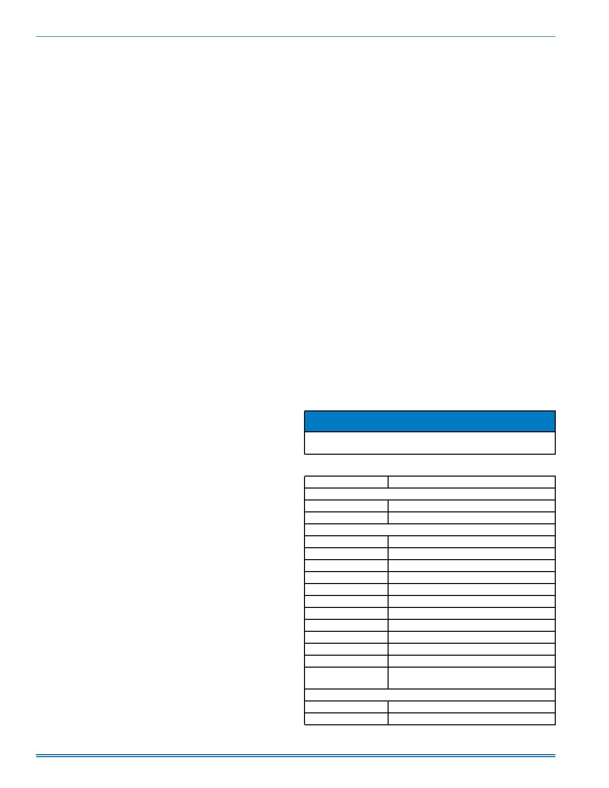
Table 14: Ignition Control Board Flash Codes
Flash Code Description
Normal Operation
Green Heartbeat Standby mode
Amber Heartbeat Call for furnace heat active
Operational Faults
Steady ON (any color) Control failure
Rapid Amber Flash Low flame current <1.5 VDC at test pad
1 Red Flash Flame sensed with gas valve off
2 Red Flashes Pressure switch closed with inducer off
3 Red Flashes Pressure switch open with inducer on
4 Red Flashes Limit switch or rollout switch open
5 Red Flashes Limit switch or rollout switch open >15 minutes
6 Red Flashes Pressure switch cycle lockout
7 Red Flashes Lockout due to failed ignition
8 Red Flashes Lockout due to too many flame dropouts
10 Red Flashes Gas valve fault
11 Red Flashes
Limit/Rollout switch open between 5 and 15
minutes
Wiring Related Faults
9 Red Flashes Incorrect low voltage polarity
4 Amber Flashes Y thermostat demand without a G
1183746-UIM-D-1015
Johnson Controls Unitary Products 17
COOLING SEQUENCE OF OPERATIONS
When the thermostat calls for COOL, the thermostat terminals G and Y
are energized, which signals the compressor, outdoor fan and indoor
blower to run.
With a call for Y, the circulating fan is energized at cooling speed.
When the thermostat is satisfied, terminals G and Y are de-energized,
de-energizing the compressor and outdoor fan.
After a cool fan off delay timing of 30 seconds, the circulating fan is de-
energized.
Safety Controls
The control circuit includes the following safety controls:
High Pressure Switch (HP) - This switch protects against excessive dis-
charge pressures due to a blocked condenser coil or a condenser
motor failure (opens at 650 ± 25 psig and closes at 450 ± 25 psig).
The above pressure switches are specifically designed to operate with
R-410A systems. R-22 pressure switches must not be used as replace-
ments for the R-410A pressure switches.
Circulating Fan
When the thermostat calls for FAN, the thermostat terminal G is ener-
gized signaling the circulating fan to run at the G-Speed airflow.
If a call for COOL occurs (Y), the circulating fan switches to run at the Y-
Speed airflow.
If a call for HEAT occurs (W), the circulating fan switches to W-Speed
after a 30 second delay.
When the thermostat ends the call for FAN, the thermostat terminal G is
de-energized, de-energizing the circulating fan.
START-UP
Prestart Check List
Complete the following checks before starting the unit.
1. Check the type of gas being supplied. Be sure that it is the same as
listed on the unit nameplate.
2. Make sure that the vent outlet air hood and air intake hood has
been properly installed.
Operating Instructions
1. STOP! Read the information on the unit safety label.
2. Set the thermostat to the OFF position.
3. Turn off all electrical power to the unit.
4. DO NOT try to light the burners by hand. This appliance is
equipped with an ignition device which automatically lights the
burners.
5. Remove the access panel.
6. Turn the gas valve switch to the OFF position.
7. Wait five (5) minutes to clear out any gas. If you then smell gas,
STOP! Follow B in the information on the unit safety label. If you
don't smell gas, go to the next step.
8. Turn the gas valve switch to the ON position.
9. Replace the control access panel.
10. Turn on all electric power to the unit.
11. Set the thermostat to the desired setting.
12. If the unit will not operate, follow the instructions To Turn Off Gas To
Appliance and call your service technician or gas supplier.
To Turn Off Gas To Unit
1. Set the thermostat to the OFF position.
2. Turn off all electric power to the appliance if service is to be per-
formed.
3. Remove the control access panel.
4. Turn the gas valve switch to the OFF position. DO NOT FORCE.
5. Replace the control access panel.
Post Start Check List
After the entire control circuit has been energized and the heating sec-
tion is operating, make the following checks:
1. Check for gas leaks in the unit piping as well as the supply piping.
2. Check for correct manifold gas pressures. See Checking Gas Input.
3. Check the supply gas pressure. It must be within the limits shown
on rating nameplate. Supply pressure should be checked with all
gas appliances in the building at full fire. At no time should the
standby gas line pressure exceed 13.5", nor the operating pressure
drop below 4.5" for natural gas units. If gas pressure is outside
these limits, contact the local gas utility for corrective action.
Manifold Gas Pressure Adjustment
Small adjustments to the gas flow may be made by turning the pressure
regulator adjusting screw on the automatic gas valve.
Refer to Figure 9.
Adjust as follows:
1. Remove the cap from the valve body. See Figure 9 for location.
2. To decrease the gas pressure, turn the adjusting screw counter-
clockwise.
3. To increase the gas pressure, turn the adjusting screw clockwise.
Adjustment of Temperature Rise
After about 20 minutes of operation, determine the heating temperature
rise. Take readings of both the return air and the heated air in the ducts
about six feet from the unit where they will not be affected by radiant
heat.
The temperature rise (or temperature difference between the return air
and the heated air from the unit) must lie within the range shown on the
rating plate and the data in Table 6.
After the temperature rise has been determined, the CFM can be calcu-
lated as follows:
Direct Drive Blower
All units have direct drive, multi speed standard ECM blower motors.
Connect manometer per “EXTERNAL STATIC PRESSURE SECTION”.
Place unit in cooling mode and adjust blower speed accordingly per
Table 11 or 12.
WARNING
The ability to properly perform maintenance on this equipment
requires certain expertise, mechanical skills, tools and equipment. If
you do not possess these, do not attempt to perform any mainte-
nance other than those procedures recommended in this Installation
Manual. Failure to heed this warning could result in serious injury
and possible damage to this equipment.
!
FIGURE 9: Gas Valve
NOTICE
The correct manifold pressure for natural gas furnaces is 3.5 IWG.
The correct manifold pressure for propane (LP) is 10.0 IWG.
INLET
WRENCH
BOSS
INLET
PRESSURE
PORT
ON
OFF
ON/OFF SWITCH
(Shown in ON position)
MAIN REGULATOR
ADJUSTMENT
OUTLET
OUTLET
PRESSURE
PORT
VENT PORT
A0303-001
BTUH Output
1.08 x CFM
OR
CFM=
BTUH Output
Degrees F Temp Rise =
1.08 x Degrees F Temp Rise
1183746-UIM-D-1015
18 Johnson Controls Unitary Products
EXTERNAL STATIC PRESSURE SETUP
To measure external static pressure:
Measure the supply air static pressure
Record this positive number
Measure the return air static pressure
Record this negative number
Treat the negative number as a positive and add the two numbers
together
This is total system static
CHECKING GAS HEAT INPUT
Natural Gas
1. Turn off all other gas appliances connected to the gas meter.
2. With the unit turned on, measure the time needed for one revolution
of the hand on the smallest dial on the meter. A typical gas meter
usually has a 1/2 or a 1 cubic foot test dial.
3. Using the number of seconds for each revolution and the size of the
test dial increment, find the cubic feet of gas consumed per hour
from Table 15.
If the actual input is not within 5% of the unit heating rating with allow-
ance being made for the permissible range of the regulator setting,
replace the orifice spuds with spuds of the proper size.
FIGURE 10: Measuring External Static Pressure
A0435-001
RETURN AIR
DUCT
SUPPLY AIR
DUCT
NOTICE
To find the BTU input, multiply the number of cubic feet of gas con-
sumed per hour by the BTU content of the gas in your particular
locality. (Contact your gas company for this information since it varies
widely from city to city.)
Table 15: Gas Rate Cubic Feet Per Hour
1
1. EXAMPLE: By actual measurement, it takes 38 seconds for the hand on
the 1-cubic foot dial to make a revolution with just a 100,000 BTUH furnace
running. Using this information, locate 38 seconds in the first column of
Table 15. Read across to the column headed “1 Cubic Foot,” where you will
see that 95 cubic feet of gas per hour are consumed by the furnace at that
rate. Multiply 95 x 1050 (the BTU rating of the gas obtained from the local
gas company). The result is 99,750 BTUH, which is close to the 100,000
BTUH rating of the unit.
Seconds for
One Rev.
Size of Test Dial
1/2 cu. ft. 1 cu. ft.
10 180 360
12 150 300
14 129 257
16 113 225
18 100 200
20 90 180
22 82 164
24 75 150
26 69 138
28 64 129
30 60 120
32 56 113
34 53 106
36 50 100
38 47 95
40 45 90
42 43 86
44 41 82
46 39 78
48 37 75
50 36 72
52 35 69
54 34 67
56 32 64
58 31 62
60 30 60
1183746-UIM-D-1015
Johnson Controls Unitary Products 19
SECTION VII: TYPICAL WIRING DIAGRAMS
FIGURE 11: Connection Wiring Diagram - 2 to 3 Ton Models
CONNECTION WIRING DIAGRAM
COOLING UNIT WITH GAS HEAT
WITH RECIPROCATING COMPRESSOR
208/230-1-60
POWER SUPPLY
208/230-1-60
USE COPPER
CONDUCTORS
ONLY
CAUTION - OPEN ALL DISCONNECTS
BEFORE SERVICING THIS UNIT
GND
BLK 6
PUR 1
L1 T1
BLK
C
230V
208V
PRI
COM
SINGLE POLE
XFMR
CONTACTOR
BRN S
COMPR
CONTACTOR
24V SEC
L2 T2 RED R
COIL
40 VA
BLK/WHT 12
DUAL
BLU 43
CAPACITOR
FAN
HI PRESS
RED 45
YEL 18
YEL 17
HERM
C
RED 7
1
BLK
START RELAY
2
YEL 46
125
BRN/WHT 13
3
BRN
W
START CAP
BRN 15
4
OD FAN
Y
5
MOTOR
RED 8
GRN 10
GRN
O
BLOWER
DELAY
RED 9
6
RED
LOW
R
180
VOLTAGE
C
BOX
120
BLK 5
C
BLU 23
C
90
R
RED 22
R
60
O
Y
YEL 21 Y
PUR 2
CONTROL
W
WHT 20
W
BOARD
(CONTINUOUS FAN)
(LOW)
1
G
GRN 19
G
RED 32
THERMOSTAT
RED 34
RED/GRN 36
2N
(LOW/MED)
1
ROLLOUT
LIMIT
(HEATING SPEED)
(MED)
3
WHT 33
BLOWER
G
MOTOR
2
GRN 4
3
2
1
RED/BLK 35
(COOLING SPEED)
(MED/HIGH)
4
YEL 31
4L
5
3
YEL 38
6
SHARED TAP
5C
GRN 40
9
(HIGH)
SEE NOTE 7
8
7
4
YEL 38
GAS
ORG 37
FLAME
IGNITOR
SENSOR
VALVE
ORG 39
PRESSURE
W SPD
SPARK
G SPD
CONTROL BOARD SETTINGS:
COMBUSTION BLOWER POST PURGE: 60 SEC
INDOOR BLOWER HEAT ON DELAY: 30 SEC
INDOOR BLOWER COOL OFF DELAY: 60 SEC
INDOOR BLOWER HEAT OFF DELAY: FIELD SELECT
TRANSFORMER
L1
IND
FS
Y SPD
24V COM
1
2
3
ORG
RED 28
BRN
DRAFT
CAP
MOTOR
LINE VOLTAGE
FIELD INSTALLED POWER
LOW VOLTAGE
FIELD INSTALLED CONTROL
WHT 27
YEL
BLU 30
DSI Fault Codes
Normal Operation
NOTES:
Green Heartbeat
Amber Heartbeat
Rapid Green Flashes
Standby mode
Call for furnace heat active
Control in Factory Test mode
Operational Fault Codes
Flashes
None
Slow Green Flashes
Slow Amber Flashes
Rapid Amber Flashes
4 Amber Flashes
Steady on Red
1 Red Flash
2 Red Flashes
3 Red Flashes
4 Red Flashes
5 Red Flashes
6 Red Flashes
7 Red Flashes
8 Red Flashes
9 Red Flashes
10 Red Flashes
11 Red Flashes
Fault Condition
Power Off or open fuse
Normal Operation
Normal Operation with call for heat
Low flame sense current
No G from thermostat with Y call
Control Failure
Flame present with gas off
Check pressure switch wiring
Vent OR termination problem
Airflow problem
Flame Rollout
Repeated pressure switch cycles
Failed to light burners
Loss of flame during call for heat
Incorrect polarity OR Don't have neutral
Gas valve shorted "ON"
Check blower motor/wiring
1. ALL FIELD WIRING TO BE ACCOMPLISHED FOLLOWING CITY, LOCAL AND/OR
NATIONAL CODES IN EFFECT AT THE TIME OF INSTALLATION OF THE UNIT.
2. CAUTION : LABEL ALL WIRES PRIOR TO DISCONNECTION WHEN SERVICING
CONTROLS. WIRING ERRORS CAN CAUSE IMPROPER AND DANGEROUS
OPERATION. IF ANY OF THE WIRING, AS SUPPLIED WITH THE UNIT, MUST
BE REMOVED, IT MUST BE REPLACED WITH TYPE 105 C. 600 VOLT
WIRE OR EQUIVALENT CLEARLY RENUMBERED FOR IDENTIFICATION.
VERIFY PROPER OPERATION AFTER SERVICING.
3. FACTORY WIRED FOR 230 VOLT SUPPLY POWER. FOR 208 VOLT, MOVE
BLACK WIRES FROM THE 230 TO THE 208 VOLT TAP ON THE TRANSFORMER.
4. MOTORS ARE INHERENTLY PROTECTED.
5. SEE UNIT NAMEPLATE FOR MAXIMUM FUSE AND/OR CIRCUIT BREAKER SIZE
AND MINIMUM CIRCUIT AMPACITY.
6. SELECT INDOOR BLOWER SPEED TO REMAIN WITHIN THE TEMPERATURE
RISE RANGE ON THE NAMEPLATE IN HEATING AND TO OBTAIN APPROX.
400 CFM/TON IN COOLING.
7. BLOWER MOTOR SPEED CONNECTIONS SHOWN ARE TYPICAL,
BUT MAY VARY BY MODEL AND APPLICATION.
BLU 42
BLK
GRN 44
PUR 26
BLK/WHT 11
1183746-UIM-D-1015
20 Johnson Controls Unitary Products
FIGURE 12: Ladder Wiring Diagram - 2 to 3 Ton Models
LADDER WIRING DIAGRAM
COOLING UNIT WITH GAS HEAT
WITH RECIPROCATING COMPRESSOR
208/230-1-60
CAUTION - OPEN ALL DISCONNECTS
BEFORE SERVICING THIS UNIT
GROUND
L1
LUG
L2
NOTES:
R
RED
L1
T1
BLK
C
COMPRES
S
R
RED
BLK/WHT
C
OD FAN
MOTOR
S
T2
L2
DUAL
CAPACITOR
BRN
H
C
F
RED
52
1
YEL RED
START RELAY
START CAP
BLK
L
BLOWE
MOTOR
R
N
PUR
G
CONTROL
BOARD
RELAY
PUR
WHT
DRAFT
BLK
L1
IND
MOTOR
CONTROL BOARD SETTINGS:
COMBUSTION BLOWER POST PURGE: 60 SEC
INDOOR BLOWER HEAT ON DELAY: 30 SEC
INDOOR BLOWER COOL OFF DELAY: 60 SEC
INDOOR BLOWER HEAT OFF DELAY: FIELD SELECT
LINE VOLTAGE
FIELD INSTALLED POWER
LOW VOLTAGE
FIELD INSTALLED CONTROL
CAP
208V
230V
PRI
COM
BLK
PUR
XFMR
RED
BLU
24V SEC
40 VA
DSI Fault Codes
HI PRESS
Green Heartbeat
Amber Heartbeat
Rapid Green Flashes
Standby mode
Call for furnace heat active
Control in Factory Test mode
YEL
YEL
THERMOSTAT
CONTACTOR
C
BLU
C
COIL
3A
R
RED
R
FUSE
Operational Fault Codes
O
Y
Flashes
None
Slow Green Flashes
Slow Amber Flashes
Rapid Amber Flashes
4 Amber Flashes
Steady on Red
1 Red Flash
2 Red Flashes
3 Red Flashes
4 Red Flashes
5 Red Flashes
6 Red Flashes
7 Red Flashes
8 Red Flashes
9 Red Flashes
10 Red Flashes
11 Red Flashes
Fault Condition
Y
W
WHT
W
Power Off or open fuse
Normal Operation
Normal Operation with call for heat
Low flame sense current
No G from thermostat with Y call
Control Failure
Flame present with gas off
Check pressure switch wiring
Vent OR termination problem
Airflow problem
Flame Rollout
Repeated pressure switch cycles
Failed to light burners
Loss of flame during call for heat
Incorrect polarity OR Don't have neutral
Gas valve shorted "ON"
Check blower motor/wiring
CONTROL
G
GRN
G
BOARD
RED
RED/GRN
ROLLOUT
BLU
LIMIT
3
2
1
RED/BLK
YEL
6
5
4
GRN
9
8
7
YEL
GAS
PRESSURE
VALVE
ORG
FLAME
IGNITOR
SENSOR
ORG
3
WHT
W SPD
4
2
SPARK
TRANSFORMER
L1
IND
FS
5
1
RED
G SPD
BLOWER
MOTOR
Y SPD
C
2
3
ORG
BLU
24V COM
1
YEL
RED
1. ALL FIELD WIRING TO BE ACCOMPLISHED FOLLOWING CITY, LOCAL AND/OR
NATIONAL CODES IN EFFECT AT THE TIME OF INSTALLATION OF THE UNIT.
2. CAUTION : LABEL ALL WIRES PRIOR TO DISCONNECTION WHEN SERVICING
CONTROLS. WIRING ERRORS CAN CAUSE IMPROPER AND DANGEROUS
OPERATION. IF ANY OF THE WIRING, AS SUPPLIED WITH THE UNIT, MUST
BE REMOVED, IT MUST BE REPLACED WITH TYPE 105 C. 600 VOLT
WIRE OR EQUIVALENT CLEARLY RENUMBERED FOR IDENTIFICATION.
VERIFY PROPER OPERATION AFTER SERVICING.
3. FACTORY WIRED FOR 230 VOLT SUPPLY POWER. FOR 208 VOLT, MOVE
BLACK WIRES FROM THE 230 TO THE 208 VOLT TAP ON THE TRANSFORMER.
4. MOTORS ARE INHERENTLY PROTECTED.
5. SEE UNIT NAMEPLATE FOR MAXIMUM FUSE AND/OR CIRCUIT BREAKER SIZE
AND MINIMUM CIRCUIT AMPACITY.
6. SELECT INDOOR BLOWER SPEED TO REMAIN WITHIN THE TEMPERATURE
RISE RANGE ON THE NAMEPLATE IN HEATING AND TO OBTAIN APPROX.
400 CFM/TON IN COOLING.
7. BLOWER MOTOR SPEED CONNECTIONS SHOWN ARE TYPICAL,
BUT MAY VARY BY MODEL AND APPLICATION.
BLK/WHT
BRN
BRN/WHT
  • Page 1 1
  • Page 2 2
  • Page 3 3
  • Page 4 4
  • Page 5 5
  • Page 6 6
  • Page 7 7
  • Page 8 8
  • Page 9 9
  • Page 10 10
  • Page 11 11
  • Page 12 12
  • Page 13 13
  • Page 14 14
  • Page 15 15
  • Page 16 16
  • Page 17 17
  • Page 18 18
  • Page 19 19
  • Page 20 20
  • Page 21 21
  • Page 22 22
  • Page 23 23
  • Page 24 24
  • Page 25 25
  • Page 26 26

Johnson Controls PCG4A24 Installation guide

Category
Heat pumps
Type
Installation guide
This manual is also suitable for

Ask a question and I''ll find the answer in the document

Finding information in a document is now easier with AI