Page is loading ...

20
REFRIGERATION PERFORMANCE CHECK
Check that compressor RLA corresponds to values shown in Ap-
pendix B. RLA draw can be much lower than values listed at low
load conditions and low ambient condensing temperatures. Val-
ues in Appendix B can slightly exceed at high load conditions and
high ambient condensing temperatures.
FINAL SYSTEM CHECKS
1. Check to see if all supply and return air grilles are adjusted
and the air distribution system is balanced for the best
compromise between heating and cooling.
2. Check for air leaks in the ductwork. See Sections on Air
Flow Adjustments.
3. Make sure the unit is free of “rattles”, and the tubing in
the unit is free from excessive vibration. Also make sure
tubes or lines are not rubbing against each other or sheet
metal surfaces or edges. If so, correct the trouble.
4. Set the thermostat at the appropriate setting for cooling
and heating or automatic changeover for normal use.
5. Be sure the Owner is instructed on the unit operation, filter,
servicing, correct thermostat operation, etc.
MAINTENANCE
HIGH VOLTAGE!
D
ISCONNECT
ALL
POWER
BEFORE
SERVICING
OR
INSTALLING
THIS
UNIT
. M
ULTIPLE
POWER
SOURCES
MAY
BE
PRESENT
. F
AILURE
TO
DO
SO
MAY
CAUSE
PROPERTY
DAMAGE
,
PERSONAL
INJURY
OR
DEATH
.
WARNING
T
O
PREVENT
PERSONAL
INJURY
OR
DEATH
DUE
TO
IMPROPER
INSTALLATION
,
ADJUSTMENT
,
ALTERATION
,
SERVICE
OR
MAINTENANCE
,
REFER
TO
THIS
MANUAL
. F
OR
ADDITIONAL
ASSISTANCE
OR
INFORMATION
,
CONSULT
A
QUALIFIED
INSTALLER
,
SERVICE
AGENCY
OR
THE
GAS
SUPPLIER
.
WARNING
S
HEET
METAL
PARTS
,
SCREWS
,
CLIPS
AND
SIMILAR
ITEMS
INHERENTLY
HAVE
SHARP
EDGES
,
AND
IT
IS
NECESSARY
THAT
THE
INSTALLER
AND
SERVICE
PERSONNEL
EXERCISE
CAUTION
.
CAUTION
Preventive maintenance is the best way to avoid unnecessary ex-
pense and inconvenience. Have this system inspected at regular
intervals by qualified service personnel, at least twice a year. Rou-
tine maintenance should cover the following items:
1. Tighten all belts, set screws, and wire connections.
2. Clean evaporator and condenser coils mechanically or with
cold water, if necessary. Usually any fouling is only matted
on the entering air face of the coil and can be removed by
brushing.
3. Lubricate motor bearings.
4. Align or replace belts as needed.
5. Replace filters as needed (see below).
6. Check for blockage of condensate drain.
7. Check power and control voltages.
8. Check running amperage.
9. Check operating temperatures and pressures.
10. Check and adjust temperature and pressure controls.
11. Check and adjust damper linkages.
12. Check operation of all safety controls.
13. Examine gas furnaces (see below and the User’s
Information Manual).
14. Check condenser fans and tighten set screws.
FILTERS
CAUTION
T
O PREVENT PROPERTY DAMAGE DUE TO FIRE AND LOSS OF
EQUIPMENT EFFICIENCY OR EQUIPMENT DAMAGE DUE TO DUST AND LINT
BUILD UP ON INTERNAL PARTS, NEVER OPERATE UNIT WITHOUT AN AIR
FILTER INSTALLED IN THE RETURN AIR SYSTEM.
Every application may require a different frequency of replace-
ment of dirty filters. Filters must be replaced at least every three
(3) months during operating seasons.
Dirty filters are the most common cause of inadequate heating or
cooling performance. Filter inspection should be made at least
every two months; more often if necessary because of local condi-
tions and usage.
Dirty throwaway filters should be discarded and replaced with a
new, clean filter.
Disposable return air filters are supplied with this unit. See the
unit Specification Sheet or Technical Manual for the correct size
and part number. To remove the filters, remove the filter access
panel on return side of the unit.
CABINET FINISH MAINTENANCE
Use a fine grade automotive wax on the cabinet finish to maintain
the finish’s original high luster. This is especially important in in-
stallations with extended periods of direct sunlight.
CLEAN OUTSIDE COIL (QUALIFIED SERVICER ONLY)
The coil with the outside air flowing over it should be inspected
annually and cleaned as frequently as necessary to keep the finned
areas free of lint, hair and debris.
CONDENSER AND INDUCED DRAFT MOTORS
Bearings on the condenser fan motors and the combustion fan
motor are permanently lubricated. No additional oiling is required.
FLAME SENSOR (QUALIFIED SERVICER ONLY)
A drop in the flame current can be caused by a nearly invisible
coating on the flame sensor. This coating, created by the fuel or
combustion air supply, can be removed by carefully cleaning the
flame sensor with steel wool.
NOTE: After cleaning, the microamp signal should be stable and in
the range of 4 - 6 microamps DC.

21
FLUE PASSAGES (QUALIFIED SERVICER ONLY)
At the start of each heating season, inspect and, if necessary, clean
the unit flue passage.
LUBRICATION
The fan shaft bearings, the 1 to 2 HP supply fan motors, the con-
denser fan motors and compressors are permanently lubricated.
INSPECTION & CLEANING
All flue product carrying areas of the furnace, its vent system, and
main burners should be examined by a qualified service agency
before the start of each heating season. This examination is neces-
sary for continued safe operation. Particular attention should be
given to deterioration from corrosion or other sources. This ex-
amination is accomplished in the following manner.
1. Disconnect power to the unit and remove furnace section
access panel.
2. Remove burner assembly:
a. Disconnect the wires from the gas valve after noting which
wires are connected to each terminal.
b. Disconnect wires from the flame rod and ignition
electrode.
c. Disconnect the gas piping at the union.
d. The entire burner assembly can now be removed from
the unit.
NOTE: Use all screws that were removed; they are necessary for
safe and proper operation of the unit.
3. Inspect and periodically clean the vent outlet (bird screen)
on the access panel.
NOTE: Periodic observation of the flame and a log of C0
2
measurements are recommended. This will aid in determining
whether the furnace is operating efficiently or if the furnace
requires cleaning.
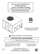
Flames should be stable, soft and blue (dust may cause orange
tips but must not be yellow). The flames must extend directly out-
ward from the burner without curling, floating or lifting off.
Check the burner flames for:
1. Good adjustment
2. Stable, soft and blue
3. Not curling, floating, or lifting off.
Burner Flame
WARNING
T
O AVOID PERSONAL INJURY OR DEATH DUE TO ELECTRIC SHOCK,
DO NOT REMOVE ANY INTERNAL COMPARTMENT COVERS OR ATTEMPT ANY
ADJUSTMENT.
C
ONTACT A QUALIFIED SERVICER AT ONCE IF AN ABNORMAL
FLAME SHOULD DEVELOP.
At least once a year, prior to or during the heating season, make a
visual check of the burner flames.
NOTE: This will involve removing and reinstalling the heat
exchanger door on the unit, which is held by two screws. If you are
uncertain about your ability to do this, contact a qualified servicer.
If a strong wind is blowing, it may alter the airflow pattern within
the unit enough that an inspection of the burner flames is not
possible.
FUNCTIONAL PARTS
Refer to the unit Parts Catalog for a list of functional parts. Parts
are available from your distributor.
TROUBLESHOOTING
IGNITION CONTROL ERROR CODES
The following presents probable causes of questionable unit op-
eration. Refer to Diagnostic Indicator Chart for an interpretation
of the signal and to this section for an explanation.
Remove the control box access panel and note the number of di-
agnostic LED flashes. Refer to Diagnostic Indicator Chart for an
interpretation of the signal and to this section for an explanation.
Internal Control Failure
If the integrated ignition control in this unit encounters an inter-
nal fault, it will go into a “hard” lockout and turn off the diagnostic
LED. If diagnostic LED indicates an internal fault, check power sup-
ply to unit for proper voltage, check all fuses, circuit breakers and
wiring. Disconnect electric power for five seconds. If LED remains
off after restoring power, replace control.
ABNORMAL OPERATION - HEATING CODES
External Lockout (1 FLASH CODE)
An external lockout occurs if the integrated ignition control deter-
mines that a measurable combustion cannot be established within
three (3) consecutive ignition attempts. If flame is not established
within the seven (7) second trial for ignition, the gas valve is
deenergized, 15 second inter-purge cycle is completed, and igni-
tion is reattempted. The control will repeat this routine three times
if a measurable combustion is not established. The control will
then shut off the induced draft blower and go into a lockout state.
If flame is established but lost, the control will energize the circu-
lator blower at the heat speed and then begin a new ignition se-
quence. If flame is established then lost on subsequent attempts,
the control will recycle for four (4) consecutive ignition attempts
(five attempts total) before locking out.

22
The diagnostic fault code is 1 flash for a lockout due to failed igni-
tion attempts or flame dropouts. The integrated control will auto-
matically reset after one hour, or it can be reset by removing the
thermostat signal or disconnecting the electrical power supply for
over five seconds. If the diagnostic LED indicates an external lock-
out, perform the following checks:
• Check the supply and manifold pressures
• Check the gas orifices for debris
• Check gas valve for proper operation
• Check secondary limit
A dirty filter, excessive duct static, insufficient air flow,
a faulty limit, or a failed circulator blower can cause
this limit to open. Check filters, total external duct
static, circulator blower motor, blower motor speed tap
(see wiring diagram), and limit. An interruption in
electrical power during a heating cycle may also cause
the auxiliary limit to open. The automatic reset
secondary limit is located on top of the circulator
blower assembly.
• Check rollout limit
If the burner flames are not properly drawn into the
heat exchanger, the flame rollout protection device will
open. Possible causes are restricted or blocked flue
passages, blocked or cracked heat exchanger, a failed
induced draft blower, or insufficient combustion air.
The rollout protection device is a manual reset limit
located on the burner bracket. The cause of the flame
rollout must be determined and corrected before
resetting the limit.
• Check flame sensor
A drop in flame signal can be caused by nearly invisible
coating on the sensor. Remove the sensor and carefully
clean with steel wool.
• Check wiring
Check wiring for opens/shorts and miswiring.
IMPORTANT: If you have to frequently reset your gas/electric
package unit, it means that a problem exists that should be
corrected. Contact a qualified servicer for further information.
Pressure Switch Stuck Open (2 FLASH CODE)
IA pressure switch stuck open can be caused by a faulty pressure
switch, faulty wiring, a disconnected or damaged hose, a blocked
or restricted flue, or a faulty induced draft blower. If the control
senses an open pressure switch during the pre-purge cycle, the
induced draft blower only will be energized.
If the pressure switch opens after ignition has begun the gas valve
is deenergized, the circulator blower heat off cycle begins, and the
induced draft blower remains on. The diagnostic fault code is two
flashes.
Pressure Switch Stuck Closed (3 FLASH CODE)
A stuck closed pressure switch can be caused by a faulty pressure
switch or faulty wiring. If the control encounters a pressure switch
stuck closed, the induced draft blower remains off. The diagnostic
LED code for this fault is three (3) flashes.
Open Thermal Protection Device (4 FLASH CODE)
If the primary limit switch opens, the gas valve is immediately
deenergized, the induced draft and air circulating blowers are en-
ergized. The induced draft and air circulator blowers remain en-
ergized until the limit switch recloses. The diagnostic fault code
for an open limit is four (4) flashes.
A primary limit will open due to excessive supply air temperatures.
This can be caused by a dirty filter, excessive duct static, insuffi-
cient air flow, or a faulty limit. Check filters, total external duct
static, blower motor, blower motor speed tap (see wiring diagram),
and limit. This limit will automatically reset once the temperature
falls below a preset level.
Flame Detected with Gas Valve Closed (5 FLASH CODE)
If flame is detected with the gas valve deenergized, the combus-
tion and air circulator blowers are energized. The diagnostic fault
code is five (5) flashes for this condition. The control can be reset
by removing the power supply to the unit or it will automatically
reset after one hour. Miswiring is the probable cause for this fault.
ABNORMAL OPERATION - COOLING CODES
Short Cycle Compressor Delay (6 FLASH CODE)
The automatic ignition control has a built-in feature that prevents
damage to the compressor in short cycling situations. In the event
of intermittent power losses or intermittent thermostat operation,
the ignition control will delay output to the compressor contactor
for three minutes from the time power is restored. (Compressor
is off a total of three minutes). The diagnostic LED will flash six (6)
times to indicate the compressor contactor output is being de-
layed.
NOTE: Some electronic thermostats also have a built-in compressor
short cycle timer that may be longer than the three minute delay
given above. If you are using an electronic thermostat and the
compressor has not started after three minutes, wait an additional
five minutes to allow the thermostat to complete its short cycle
delay time.
/