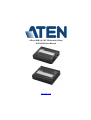
ATEN 4-Port USB 2.0 CAT 5 Extender UCE32100 User manual
- Category
- Console extenders
- Type
- User manual
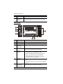
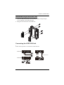
ATEN 4-Port USB 2.0 CAT 5 Extender UCE32100 allows you to extend USB connectivity over long distances with its USB 2.0 transparent extension capability that supports speeds up to 480 Mbps. Its compact size and flexible installation options make it suitable for various environments, while the integrated 4-port hub and power supply at the receiver unit ensure compatibility with multiple USB devices.
ATEN 4-Port USB 2.0 CAT 5 Extender UCE32100 allows you to extend USB connectivity over long distances with its USB 2.0 transparent extension capability that supports speeds up to 480 Mbps. Its compact size and flexible installation options make it suitable for various environments, while the integrated 4-port hub and power supply at the receiver unit ensure compatibility with multiple USB devices.


-
 1
1
-
 2
2
-
 3
3
-
 4
4
-
 5
5
-
 6
6
-
 7
7
-
 8
8
-
 9
9
-
 10
10
-
 11
11
-
 12
12
-
 13
13
-
 14
14
-
 15
15
-
 16
16
-
 17
17
-
 18
18
-
 19
19
-
 20
20
-
 21
21
-
 22
22
-
 23
23
-
 24
24
-
 25
25


ATEN 4-Port USB 2.0 CAT 5 Extender UCE32100 User manual
- Category
- Console extenders
- Type
- User manual
ATEN 4-Port USB 2.0 CAT 5 Extender UCE32100 allows you to extend USB connectivity over long distances with its USB 2.0 transparent extension capability that supports speeds up to 480 Mbps. Its compact size and flexible installation options make it suitable for various environments, while the integrated 4-port hub and power supply at the receiver unit ensure compatibility with multiple USB devices.
Ask a question and I''ll find the answer in the document
Finding information in a document is now easier with AI

