Hitachi H 60MEY is a powerful demolition hammer designed for heavy-duty tasks such as breaking concrete, asphalt, and other hard materials. With its robust construction and advanced technology, it delivers exceptional performance even under the most demanding conditions. The H 60MEY features an ergonomic design to reduce user fatigue and improve comfort during extended use, making it an ideal tool for professionals working in construction or demolition industries.
Hitachi H 60MEY is a powerful demolition hammer designed for heavy-duty tasks such as breaking concrete, asphalt, and other hard materials. With its robust construction and advanced technology, it delivers exceptional performance even under the most demanding conditions. The H 60MEY features an ergonomic design to reduce user fatigue and improve comfort during extended use, making it an ideal tool for professionals working in construction or demolition industries.


-
 1
1
-
 2
2
-
 3
3
-
 4
4
-
 5
5
-
 6
6
-
 7
7
-
 8
8
-
 9
9
-
 10
10
-
 11
11
-
 12
12
-
 13
13
-
 14
14
-
 15
15
-
 16
16
-
 17
17
-
 18
18
-
 19
19
-
 20
20
-
 21
21
-
 22
22
-
 23
23
-
 24
24
-
 25
25
-
 26
26
-
 27
27
-
 28
28
-
 29
29


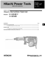
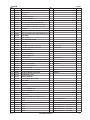
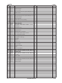
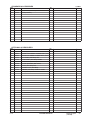
Hitachi H 60ME User manual
- Type
- User manual
- This manual is also suitable for
Hitachi H 60MEY is a powerful demolition hammer designed for heavy-duty tasks such as breaking concrete, asphalt, and other hard materials. With its robust construction and advanced technology, it delivers exceptional performance even under the most demanding conditions. The H 60MEY features an ergonomic design to reduce user fatigue and improve comfort during extended use, making it an ideal tool for professionals working in construction or demolition industries.
Ask a question and I''ll find the answer in the document
Finding information in a document is now easier with AI
Related papers
-
Hitachi DH 40MEY User manual
-
-
-
-
-
-
-
-
-
Other documents
-
Winners Only GC268CW Assembly Instructions
-
-
-
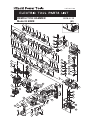
 Neu Master Electric Brad Nailer User manual
-
REXON DH410R Owner's manual
-
 Rock Slide Engineering BULL BAR LIGHT Installation guide
-
Vestax VAI-80 User manual
-
Sanyo ECJ-HC100S User manual
-
Samsung SCX-5112 User manual
-
CyberData 011388 Owner's manual

