Page is loading ...

User Guide
ISS 608
Seamless Switchers
True Seamless 4K/60 HDMI and DisplayPort Switcher
68-2994-01 Rev. B
09 20

Safety Instructions
Safety Instructions • English
WARNING: This symbol, , when used on the product, is intended to
alert the user of the presence of uninsulated dangerous voltage within
the product’s enclosure that may present a risk of electric shock.
ATTENTION: This symbol, , when used on the product, is intended
to alert the user of important operating and maintenance (servicing)
instructions in the literature provided with the equipment.
For information on safety guidelines, regulatory compliances, EMI/EMF
compatibility, accessibility, and related topics, see the Extron Safety and
Regulatory Compliance Guide, part number 68-290-01, on the Extron website,
www.extron.com.
Sicherheitsanweisungen • Deutsch
WARUNG: Dieses Symbol auf demProdukt soll den Benutzer darauf
aufmerksam machen, dass im Inneren des Gehäuses dieses Produktes
gefährliche Spannungen herrschen, die nicht isoliert sind und die einen
elektrischen Schlag verursachen können.
VORSICHT: Dieses Symbol auf dem Produkt soll dem Benutzer in
der im Lieferumfang enthaltenen Dokumentation besonders wichtige
Hinweise zur Bedienung und Wartung (Instandhaltung) geben.
Weitere Informationen über die Sicherheitsrichtlinien, Produkthandhabung,
EMI/EMF-Kompatibilität, Zugänglichkeit und verwandte Themen finden Sie in den
Extron-Richtlinien für Sicherheit und Handhabung (Artikelnummer
68-290-01) auf der Extron-Website, www.extron.com.
Instrucciones de seguridad • Español
ADVERTENCIA: Este símbolo, , cuando se utiliza en el producto, avisa
al usuario de la presencia de voltaje peligroso sin aislar dentro del
producto, lo que puede representar un riesgo de descarga eléctrica.
ATENCIÓN: Este símbolo, , cuando se utiliza en el producto,
avisa al usuario de la presencia de importantes instrucciones de
uso y mantenimiento estas estan incluidas en la documentación
proporcionada con el equipo.
Para obtener información sobre directrices de seguridad, cumplimiento
de normativas, compatibilidad electromagnética, accesibilidad y temas
relacionados, consulte la Guía de cumplimiento de normativas y seguridad de
Extron, referencia 68-290-01, en el sitio Web de Extron, www.extron.com.
Instructions de sécurité • Français
AVERTISSEMENT : Ce pictogramme, , lorsqu’il est utilisé sur le
produit, signale à l’utilisateur la présence à l’intérieur du boîtier du
produit d’une tension électrique dangereuse susceptible de provoquer
un choc électrique.
ATTENTION : Ce pictogramme, , lorsqu’il est utilisé sur le produit,
signale à l’utilisateur des instructions d’utilisation ou de maintenance
importantes qui se trouvent dans la documentation fournie avec
l’équipement.
Pour en savoir plus sur les règles de sécurité, la conformité à la réglementation,
la compatibilité EMI/EMF, l’accessibilité, et autres sujets connexes, lisez les
informations de sécurité et de conformité Extron, réf. 68-290-01, sur le site
Extron, www.extron.com.

Copyright
© 2019-2020 Extron. All rights reserved. www.extron.com
Trademarks
All trademarks mentioned in this guide are the properties of their respective owners.
The following registered trademarks (
®
) and registered service marks (
SM
) are the property of RGBSystems, Inc. The trademarks (
TM
) are the property of
RGBSystems, Inc. or Extron (see the current list of trademarks on the Terms of Use page at www.extron.com):
Registered Trademarks
(
®
)
Extron, Cable Cubby, ControlScript, CrossPoint, DTP, eBUS, EDID Manager, EDID Minder, eLink, Flat Field, FlexOS, Glitch Free, GlobalConfigurator,
GlobalScripter, GlobalViewer, Hideaway, HyperLane, IPIntercom, IPLink, KeyMinder, LinkLicense, LockIt, MediaLink, MediaPort, NAV,
NetPA, PlenumVault, PoleVault, PowerCage, PURE3, Quantum, ShareLink, Show Me, SoundField, SpeedMount, SpeedSwitch, StudioStation,
SystemINTEGRATOR, TeamWork, TouchLink, V-Lock, VideoLounge, VN-Matrix, VoiceLift, WallVault, WindoWall, XPA, XTP, XTPSystems, and ZipClip
Registered Service Mark
(SM)
: S3 Service Support Solutions
Trademarks
(
™
)
AAP, AFL (Accu-RATEFrameLock), ADSP(Advanced Digital Sync Processing), Auto-Image, AVEdge, CableCover, CDRS(ClassD Ripple
Suppression), Codec Connect, DDSP(Digital Display Sync Processing), DMI (DynamicMotionInterpolation), DriverConfigurator, DSPConfigurator,
DSVP(Digital Sync Validation Processing), EQIP, Everlast, FastBite, Flex55, FOX, FOXBOX, IP Intercom HelpDesk, MAAP, MicroDigital, Opti-Torque,
PendantConnect, ProDSP, QS-FPC(QuickSwitch Front Panel Controller), RoomAgent, Scope-Trigger, SIS, SimpleInstructionSet, Skew-Free,
SpeedNav, Triple-Action Switching, True4K, True8K, Vector™ 4K, WebShare, XTRA, and ZipCaddy

FCC Class A Notice
This equipment has been tested and found to comply with the limits for a Class A digital
device, pursuant to part15 of the FCC rules. The ClassA limits provide reasonable
protection against harmful interference when the equipment is operated in a commercial
environment. This equipment generates, uses, and can radiate radio frequency energy and,
if not installed and used in accordance with the instruction manual, may cause harmful
interference to radio communications. Operation of this equipment in a residential area is
likely to cause interference. This interference must be corrected at the expense of the user.
NOTES:
• This unit was tested with shielded I/O cables on the peripheral devices. Shielded
cables must be used to ensure compliance with FCC emissions limits.
• For more information on safety guidelines, regulatory compliances, EMI/EMF
compatibility, accessibility, and related topics, see the Extron Safety and
Regulatory Compliance Guide on the Extron website.

Conventions Used in this Guide
Notifications
The following notifications are used in this guide:
ATTENTION:
• Risk of property damage.
• Risque de dommages matériels.
NOTE: A note draws attention to important information.
TIP: A tip provides a suggestion to make working with the application easier.
Software Commands
Commands are written in the fonts shown here:
^AR Merge Scene,,0p1 scene 1,1 ^B 51 ^W^C.0
[01] R 0004 00300 00400 00800 00600 [02] 35 [17] [03]
E X! *X1&* X2)* X2#* X2! CE}
NOTE: For commands and examples of computer or device responses used in this
guide, the character “0” is the number zero and “O” is the capital letter “o.”
Computer responses and directory paths that do not have variables are written in the font
shown here:
Reply from 208.132.180.48: bytes=32 times=2ms TTL=32
C:\Program Files\Extron
Variables are written in slanted form as shown here:
ping xxx.xxx.xxx.xxx —t
SOH R Data STX Command ETB ETX
Selectable items, such as menu names, menu options, buttons, tabs, and field names are
written in the font shown here:
From the File menu, select New.
Click the OK button.
Specifications Availability
Product specifications are available on the Extron website, www.extron.com.
Extron Glossary of Terms
A glossary of terms is available at http://www.extron.com/technology/glossary.aspx.


viiTechnical Publications Standards and Styles • Contents
Contents
Introduction ................................................1
About this Manual................................................ 1
About the Integration Seamless Switcher ............. 1
Features .............................................................. 2
Installation .................................................. 6
Mounting the ISS608 .......................................... 6
Rear Panel Overview ........................................... 6
Power Connection ........................................... 6
Video Input Connections .................................. 6
Output Connections ........................................ 7
Reset Button ................................................... 7
Control Connections ........................................ 9
Operation..................................................11
Front Panel Controls and Indicators ................... 11
Mute, Freeze, Input Selection,
and Effects Controls ..................................... 11
Picture Adjustment and
Menu System Controls ................................. 12
Front Panel Security Lockout
(Executive Modes) ........................................ 13
Front Panel Menu Operation .............................. 13
Menu Navigation ............................................ 13
Menu Overview ............................................. 14
Input Presets Menu........................................ 15
Picture Controls Menu ................................... 16
Input Configuration Menu .............................. 17
Output Configuration Menu............................ 18
Effect Configuration Menu.............................. 20
Background/Logo Configuration Menu .......... 23
Advanced Configuration Menu ....................... 25
View and Edit Communications
Settings Menu .............................................. 27
Exit Menu ...................................................... 28
Front Panel Button Operations........................... 29
Front Panel Button Shortcuts ......................... 29
Front Panel Button Colors .............................. 29
Selecting an Input .......................................... 30
Switching the Preview Output to
the Program Output ...................................... 30
Recalling a Layout Preset............................... 30
Configuring and Recalling a Logo Preset ....... 31
Adjusting the Size and Position
of the Program or Preview ............................ 32
Matrix Mode ...................................................... 33
Upstream Signal Switching and
Local Video Bus Switching ............................... 34
SIS Configuration and Control ...................35
Connections Options ......................................... 35
Rear Panel RS-232 Port ................................ 35
Front Panel Configuration USB Port ............... 35
Ethernet Link ................................................. 35
Default Address ............................................. 36
Symbols ........................................................ 36
Host-to-Switcher Communications .................... 36
Switcher-Initiated Messages .............................. 36
Switcher Error Responses ............................. 37
Using the Command and Response Tables ....... 38
Command and Response Tables ....................... 43
Configuration Software .............................58
Software/Firmware Installation ........................... 58
Connecting to PCS ............................................ 60
Device Discovery Panel .................................. 60
TCP/IP Panel ................................................. 61
Offline Device Preview .................................... 61
Software Overview ............................................. 62
Software Menu .............................................. 63
Device Menu.................................................. 65

Technical Publications Standards and Styles • Contents viii
Internal Web Page ..................................... 67
Accessing the Internal Web Page ...................... 67
Disabling Compatibility Mode ......................... 68
Web Page Panels .............................................. 68
Device Info Panel ........................................... 69
Device Status Panel ....................................... 69
Network Settings Panel ................................. 70
Inputs Panel................................................... 70
Outputs Panel ................................................ 71
RS-232 Panel ................................................ 71
Firmware Panel .............................................. 72
Roles and Permissions Panel ......................... 72
About the ISS608 ......................................... 73
Reference Information ...............................74
Mounting the Switcher ....................................... 74
Tabletop Placement ....................................... 74
Rack Mounting .............................................. 74
Front Panel Menu Diagrams ............................. 76
Input Presets, Picture Controls, Input
Configuration, and Output Configuration ....... 76
Effect Configuration ....................................... 77
Background/Logo Configuration .................... 78
Advanced Configuration and
View Comm Settings .................................... 79

ISS 608 Seamless Switcher • Introduction 1
Introduction
The topics in this section are:
• About this Manual
• About the Integration Seamless Switcher
• Features
About this Manual
This manual contains installation, configuration, and operating information for the Extron
ISS608 Integration Seamless Switcher.
About the Integration Seamless Switcher
The Extron ISS608 is an eight-input, scaling, video and audio seamless switcher for the
dynamic presentation of HDMI and DisplayPort content at resolutions up to 4K/60Hz.
With six HDMI 2.0 and two DisplayPort 1.2 inputs that support signals up to 4096x2160 at
60Hz with 4:4:4 color sampling, the ISS combines true seamless switching with advanced
Vector™ 4K scaling technology.
NOTE: The terms ISS, ISS608, scaler, and switcher refer to the ISS608.
The ISS provides multiple seamless transition effects, an independent preview output, and
intuitive front panel operation. Logo insertion, video keying, and Picture In Picture (PIP)
capabilities complement primary content, and audio de-embedding simplifies integration.
Matrix Mode (see page33) adds automatic, seamless transitions to matrix switchers
with HDMI outputs. In addition, RS-232 and Ethernet provide optimal control options.
These features and capabilities enable the ISS608 to deliver a true seamless digital signal
switching solution perfect for high-end, live presentation environments.
Figure1 on page2 shows a typical ISS608 application. The switcher accepts up to
eight video inputs of various resolutions, scales the video inputs, and outputs video and
audio.
The ISS 608 seamlessly switches between the program and preview inputs without a loss
of video or sync. The ISS offers a wide range of effects that eliminate distracting jumps,
glitches, and delays, as well as allows the user to choose transitions most appropriate for
the material. Effects include wipes with selectable direction and duration, a dissolve with
selectable duration, and a seamless cut. The audio transition can also be accompanied by
either a cut or a fade audio effect.
Each video input is individually configurable to support different video formats. The ISS
allows the various high-resolution and low-resolution video formats to be seamlessly
switched between for display in high profile, professional presentation spaces.
The ISS provides two separate outputs:
• Program output — The program output is the video seen by the audience.
• Preview output — The preview output allows the switcher operator to view the video
before it is transitioned to the program output for the audience to see.

ISS 608 Seamless Switcher • Introduction 2
RESET
100-240V --A MAX
50-60 Hz
HDMI
1
HDMI
2
HDMI
3
HDMI
4
HDMI
1A
HDMI DISPLAYPORT
6 7
DISPLAYPORT
8
HDMI
2A
INPUTS
ISS 608
OUTPUTSPREVIEW PROGRAM
AUDIO
REMOTE
HDMI
5
PREVIEW
L R
PROGRAM
L R
LAN
Tx Rx
RS-232
G
POWER
12V
1A MAX
G
Tx Rx RTS CTS
COM 1
G
Tx Rx
COM 2
V C G
VOL
RELAYS
1 2 C
1 2 3 4 G
DIGITAL I/O
PWR OUT = 6W
eBUS
+V +S
-S
G
LAN
IPCP PRO 250
IR/S
S G
DMP 64
DIGITAL MATRIX PROCESSOR
INPUTS
CLIP
SIGNAL
1 2 3 4 5 6
CONFIG
OUTPUTS
CLIP
SIGNAL
1 2 3 4
XPA 2001
LIMITER/PROTECT
SIGNAL
OVER
TEMP
Extron
SF 26CT
Full-Range
Ceiling Speakers
Audio
Audio
Audio
Audio
Ethernet
Ethernet
Ethernet
HDMI
HDMI
HDMIHDMI
HDMI
HDMI
DisplayPort
Extron
XPA 2001-70V
Power Amplier
Extron
DMP 64
Digital Matrix
Processor
Extron
IPCP Pro 250
IP Link Pro
Control Processor
Extron
TLP Pro 1720TG
17" Tabletop
TouchLink Pro
Touchpanel
Extron
ISS 608
4K/60 HDMI
and DisplayPort
Seamless Switcher
BYOD
Workstation PC
Projector
4K Media Player
Computer
DSS Receiver
Microphones
Figure 1. Typical ISS608 Integration Seamless Switcher Application
The ISS608 scales the input up or down to any of a wide variety of output resolutions
and rates. The scaler outputs the scaled video on two connectors, one HDMI program
connector and one HDMI preview connector.
The switcher features built-in test patterns to aid in display setup and evaluation.
The switcher is housed in a rack-mountable, 2U high, 17.4 inch wide, metal enclosure. The
ISS has an internal 100 VAC to 240 VAC, 50-60 Hz, 45 watts internal power supply that
provides worldwide power compatibility.
Features
• Inputs: Six female HDMI type-A and two female DisplayPort connectors.
• Outputs: Two female HDMI type-A and two 3.5 mm 5-pole captive screw connectors.
• True seamless switching between eight digital inputs — Provides sophisticated
transition effects for presentations and live events.
• Multiple transition effects include wipes, dissolve, and cut — Offers a wide range
of effects that eliminate distracting jumps, glitches, and delays, as well as allows the
user to choose transitions most appropriate for the material. Effects include wipes with
selectable direction and duration, a dissolve with selectable duration, and a seamless
cut.
• Preview and Program outputs — Independent video buses for Preview and Program
outputs enable the operator to preview and adjust video prior to displaying on the main
display.
1

ISS 608 Seamless Switcher • Introduction 3
• Advanced Extron Vector 4K scaling engine — The Vector 4K scaling engine is
specifically designed for critical-quality 4K imagery, with best-in-class image upscaling
and downscaling.
• Supports computer and video resolutions up to 4K/60 @ 4:4:4 — Supports
HDMI2.0 and DisplayPort 1.2 signals up to 4096x2160 at 60 Hz with 4:4:4 color
sampling.
• Supported HDMI 2.0 specification features include data rates up to 18 Gbps,
Deep Color, and HD lossless audio formats.
• HDCP 2.3 compliant — Ensures display of content-protected media and
interoperability with other HDCP-compliant devices.
• Matrix Mode — HDMI inputs 1 and 2 support Matrix Mode, which adds seamless
switching and transition effects to any matrix switcher with HDMI outputs.
• PIP - picture-in-picture — Allows any input to be displayed on-screen simultaneously
with another. The PIP window can be dynamically sized and positioned anywhere within
the output and is transitioned into or out of the output using the dissolve effect. Sixteen
PIP presets are also available.
• Video keying — Title information or other content from an input source can be keyed
over the Program image.
• Logo image keying and display — A logo graphic can be positioned and keyed over
live video. Logo graphics in BMP, JPG, PNG, or TIFF format may be uploaded to the
unit. Full screen images up to 4K resolution can also be displayed to eliminate loss of
video between presentations. Up to 16 logo images can be stored.
• Take button sends preview content to the audience using the selected effect
— Pressing the Take button on the front panel sends the preview content from the local
monitor to the main display device. The switch is performed with the selected effect,
providing a seamless transition between sources.
• Aspect ratio control — The aspect ratio of the video output can be controlled by
selecting a FILL mode that provides a full screen output or a FOLLOW mode, which
preserves the original aspect ratio of the input signal.
• Motion-adaptive deinterlacing for signals up to 1080i — Advanced deinterlacing
for all interlaced signals up to 1080i delivers optimized image quality.
• Automatic 3:2 and 2:2 pulldown detection — Advanced film mode processing
techniques that help maximize image quality for content sources originating from film.
• Auto-Image setup — Automatically optimizes the image by analyzing and adjusting
to the video input signal. This can save time and effort in setting up a newly connected
source, particularly in presentation environments where different guest presenter laptops
with various output resolutions will be connected.
• Auto Input Memory — When activated, the unit automatically stores size, position,
and picture settings based on the incoming signal. When the same signal is detected
again, these image settings are automatically recalled from memory.
• Input presets — Memory presets are available to store and recall image settings.
• Layout presets — Memory presets are available to store and recall user settings. This
provides a quick method to set up content preview in anticipation of transitioning it to
the Program output.
• Output mute — Allows independent muting for Preview and Program output signals.
• Output freeze — Provides independent freeze control of the program and preview
output signals. Frozen content can be switched to the Program output using any
transition effect.

ISS 608 Seamless Switcher • Introduction 4
• User-selectable HDCP authorization — Allows each HDMI input to appear HDCP
compliant or non-HDCP compliant to the connected source, which is beneficial if the
source automatically encrypts all content when connected to an HDCP-compliant
device. Protected material is not passed in non-HDCP mode.
• HDCP Visual Confirmation provides a green signal when encrypted content
is sent to a non-compliant display — A green window with an alert message is
displayed when HDCP-encrypted content is transmitted to a non-HDCP compliant
display, providing immediate visual confirmation that protected content cannot be
viewed on the display.
• Key Minder continuously verifies HDCP compliance for quick, reliable
switching — Key Minder authenticates and maintains continuous HDCP encryption
between input and output devices to ensure quick and reliable switching in professional
AV environments, while enabling simultaneous distribution of a single source signal to
one or more displays.
• SpeedSwitch Technology delivers virtually instantaneous switching speeds for
HDCP-encrypted content.
• EDID Minder automatically manages EDID communication between connected
devices — EDID Minder ensures that all sources power up properly and reliably output
content for display.
• EDID capture mode — EDID information can be captured and stored from connected
program and preview display devices.
• Comprehensive picture controls for Preview and Program output buses — Fine
tune displayed content with picture controls for brightness, contrast, sizing, positioning,
and zoom.
• Internal video test patterns and pink noise generator for calibration and setup
— The ISS offers several video test patterns and audio pink noise to facilitate proper
system setup and calibration of display devices.
• Audio management — Embedded two-channel digital audio can be extracted from
any input and sent to the Preview and Program analog audio outputs. Multi-channel
audio formats can be passed to the Preview and Program HDMI outputs.
• Easy setup and commissioning with Extron PCS - Product Configuration
Software — Convenient configuration and preset design from a single easy-to-use
software application.
• Front panel controls with LCD display — Back-lit front panel buttons and an LCD
menu system with navigation controls ensure simplified operation in live presentation
environments and provide quick access to configuration settings.
• Ethernet monitoring and control — Enables control and proactive monitoring over a
LAN or WAN.
• Built-in web pages — Enables the use of a standard browser for device monitoring
and simple troubleshooting over an intuitive web interface.
• RS-232 control port — Supports the use of serial commands for integration into
a control system. Extron products use the SIS - Simple Instruction Set command
protocol, a set of basic ASCII commands that allow for quick and easy programming.
• Front panel USB configuration port — Enables easy configuration without having to
access the rear panel.
• Executive Mode lockout — Provides restriction to access of controls.
• Includes LockIt HDMI cable lacing brackets.
• Rack-mountable 2U, full rack width metal enclosure.

ISS 608 Seamless Switcher • Introduction 5
• Internal Extron Everlast power supply — Provides worldwide power compatibility,
with high demonstrated reliability and low power consumption for reduced operating
cost.
• Extron Everlast Power Supply is covered by a 7-year parts and labor warranty.

ISS 608 Seamless Switcher • Installation 6
Installation
The topics covered in this section are:
• Mounting the ISS608
• Rear Panel Overview
Mounting the ISS608
The ISS608 is housed in a 2U high, full rack width metal enclosure that can sit on a table
with the provided rubber feet or be mounted using the attached rack mounts.
Select a suitable mounting location (see Mounting the Switcher on page75), then
choose an appropriate mounting option.
• Before connecting the ISS608, turn off all devices that are to be connected.
• Connect all external devices to the ISS before applying power.
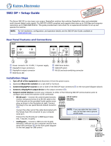
Rear Panel Overview
RESET
100-240V --A MAX
50-60 Hz
HDMI
1
HDMI
2
HDMI
3
HDMI
4
HDMI
1A
HDMI DISPLAYPORT
6 7
DISPLAYPORT
8
HDMI
2A
INPUTS
ISS 608
OUTPUTSPREVIEW PROGRAM
AUDIO
REMOTE
HDMI
5
PREVIEW
L R
PROGRAM
L R
LAN
Tx Rx
RS-232
G
FF
AA
GG HH
D
DCCBB
E
E
A AC power connector
E
Analog audio outputs
B HDMI input connectors 1 through 6
F
Reset button and LED
C DisplayPort input connectors 7 and 8
G
LAN connector
D
HDMI output connectors
H
Remote RS-232 connector
Figure 2. ISS608 Rear Panel Connectors
Power Connection
A
AC power connector — Plug a standard IEC power cord into this connector to
connect the seamless switcher to a 100 to 240 VAC, 50 Hz or 60 Hz power source.
Video Input Connections
B
HDMI input connectors 1 through 6 — Connect HDMI video to these inputs.
C
DisplayPort input connectors 7 and 8 — Connect DisplayPort video to these inputs.
2

ISS 608 Seamless Switcher • Installation 7
Output Connections
Video output connections
D
HDMI output connectors (see figure2 on page6) — Connect displays to the
Program and Preview HDMI output connectors.
• The Program connector (2A) outputs the video image for the program display or
projector.
• The Preview connector (1A) outputs the video image for the local display.
Audio output connections
E
Analog audio outputs — Connect audio devices, such as an audio amplifier or
powered speakers, to these 3.5 mm, 5-pole captive screw connectors. The connectors
output the selected unamplified, line level audio de-embedded from the HDMI and
DisplayPort inputs (see figure3 to properly wire an output connector). Use the supplied
tie-wrap to strap the audio cable to the extended tail of the connector.
Balanced Audio Output
Tip
Ring
Tip
Ring
Sleeves
Unbalanced Audio Output
Tip
No Ground Here
No Ground Here
Tip
Sleeves
LR
LR
Do not tin the wires
3/16” Max
(5mm)
Figure 3. Captive Screw Connector Wiring for Audio Output
ATTENTION:
• Connect the sleeve to the ground (Gnd) terminal. Connecting the sleeve to a
negative (-) terminal will damage the audio output circuits.
• Connectez le manchon à la borne de terre (Gnd). Connecter le manchon à une
borne négative (-) endommagera les circuits de la sortie audio.
• The length of the exposed wires in the stripping process is important. The ideal
length is 3/16 inches (5 mm). Any longer and the exposed wires may touch,
causing a short circuit between them. Any shorter and the wires can be easily
pulled out even if tightly fastened by the captive screws.
• La longueur des câbles exposés est importante lorsque l’on entreprend de
les dénuder. La longueur idéale est de 5 mm (3/16 inches). S’ils sont trop
longs, les câbles exposés pourraient se toucher et provoquer un court-
circuit. S’ils sont trop courts, ils peuvent être tirés facilement, même s’ils sont
correctement serrés par les borniers à vis.
By default, the de-embedded analog audio output follows the video switch, but it can
be split via SIS commands (see Audio follow on page49). Audio output can also be
muted via SIS commands (see Audio mute (digital and analog - persists beyond a
power cycle) on page49)
Reset Button
F
Reset button and LED — Initiates four levels of reset to the switcher. Use an Extron
Tweeker or small screwdriver to press and hold the button while the switcher is running
or while you power up the switcher for different reset levels.
See the ISS608 Reset Modes table on page8 and figure4 on page9 for a
summary of the function of the reset modes and how to perform them.
3

ISS 608 Seamless Switcher • Installation 8
ATTENTION:
• Review the reset modes carefully. Some reset modes delete all user loaded
content and revert the device to default configuration.
• Analysez minutieusement les différents modes de réinitialisation. Certains
modes de réinitialisation suppriment l’intégralité du contenu chargé de
l’utilisateur et remettent l’appareil au mode de configuration par défaut.
ISS608 Reset Modes
Mode Activation Result Purpose and Notes
Use Factory Firmware
1 Hold in the recessed rear
panel Reset button while
applying power to the unit.
The ISS608 reverts to the factory
default firmware for a single power
cycle.
Use mode 1 to revert to
the factory default firmware
for a single power cycle if
incompatibility issues arise
with user-loaded firmware.
All user files and settings are
maintained.
NOTE: Do not operate with the default firmware loaded by a mode1 reset. Use it only to load the
most current firmware to the device.
Reset All IP Settings
*4
Hold in the Reset button
until the Reset LED blinks
twice (once at 3 seconds,
again at 6 seconds). Then,
release and press the
Reset button again within 1
second*.
• Sets port mapping back to
factory default.
• Sets the IP address
back to factory default
(192.168.254.254).
• Sets the subnet mask address
back to the factory default
(255.255.255.0).
• Sets the gateway IP address to
the factory default (0.0.0.0).
• Turns DHCP off.
• The Reset LED on the rear panel
of the unit flashes four times in
succession.
Mode 4 is used to set
IP address information using
ARP and the MAC address.
Resetting IP Settings
appears on a connected
display.
Reset to Factory Defaults
*5
Hold in the Reset button
until the Reset LED blinks
three times (once at 3
seconds, again at 6 seconds,
again at 9 seconds). Then,
release and press the
Reset button again within 1
second*.
Performs a complete reset to factory
defaults (except the firmware).
• Does everything mode 4 does.
• Clears port configurations.
• Resets all IP options.
• Clears all user settings.
• Clears all files from the unit.
• The Reset LED on the rear panel
of the unit flashes four times in
succession.
Mode 5 is useful to start over
with default configuration and
uploading, and also to replace
events.
Resetting ISS 608 appears
on a connected display.
Mode 5 is equivalent to
SIS command ZQQQ (see
SIS command Resets on
page55).
NOTES:
• *For modes 4 and 5, nothing happens if the momentary press does not occur within 1 second.
• The factory configured passwords for all accounts on this device have been set to the device serial
number. In the event of a complete system reset, the passwords convert to the default, which is no
password (see Passwords on page57 to change a password).

ISS 608 Seamless Switcher • Installation 9
RESET
RESET
RESET RESET
RESET RESET
RESET
RESET
Press and hold
the Reset button.
Mode 1
Apply power
to the ISS 608.
Release Reset button.
Release, then immediately
press and release again.
Reset LED flashes, then goes off.
Mode 4
Reset LED flashes twice.
Press and hold
for 6 seconds.
Release, then immediately
press and release again.
Reset LED flashes, then goes off.
Mode 5
Reset LED flashes three
times.
Press and hold
for 9 seconds.
Figure 4. Whole Switcher and Absolute Resets
Control Connections
Ethernet connection
G
LAN connector (see figure2 on page6) — Connect the seamless switcher to an
Ethernet LAN or WAN via this RJ-45 connector. Ethernet control allows the operator to
control the seamless switcher from a remote location. When connected to an Ethernet
LAN or WAN, the seamless switcher can be accessed and operated from a computer
running a standard Internet browser.
Ethernet connection indicators — The Link and Activity LEDs indicate the status of
the Ethernet connection.
• Link LED — Indicates the seamless switcher is properly connected to an Ethernet
LAN. This LED should light steadily.
• Activity LED — Indicates transmission of data packets on the RJ-45 connector.
This LED should flicker as the seamless switcher communicates.
Choosing a network cable
Ethernet links use Category (CAT) 3, 4, 5, 5e, or 6, unshielded twisted pair (UTP) or shielded
twisted pair (STP) cables, terminated with RJ-45 connectors. Ethernet cables are limited to
328 feet (100 m).
ATTENTION:
• Do not use standard telephone cables. Telephone cables do not support Ethernet
or Fast Ethernet. Do not stretch or bend cables. This can cause transmission
errors.
• Ne pas utiliser de câbles téléphone standard. Les câbles de téléphone ne sont pas
compatibles avec les liaisons Ethernet ou Fast Ethernet. Ne pas étirer ou plier les
câbles. Cela pourrait provoquer des erreurs de transmission.
The cable used depends on network speed. The ISS supports 10 Mbps (10Base-T) and
100 Mbps (100Base-T), half-duplex and full-duplex Ethernet connections.
• 10Base-T Ethernet requires at a minimum CAT 3 UTP or STP cable.
• 100Base-T Fast Ethernet requires at a minimum CAT 5 UTP or STP cable.
4

ISS 608 Seamless Switcher • Installation 10
Wiring the network cable
The cable can be terminated as either a patch cable or a crossover cable (see figure5) and
must be properly terminated for the application:
• Patch (straight-through) cable — Connection of the ISS to an Ethernet hub, router,
or switch that also hosts a controlling computer.
• Crossover cable — Direct connection between the ISS and a controlling computer.
12345678
RJ-45
Connector
Insert Twisted
Pair Wires
Pins:
A cable that is wired as TIA/EIA T568A at one
end and T568B at the other (Tx and Rx pairs
reversed) is a "crossover" cable.
A cable wired the same at both ends is called
a "straight-through" cable because no pin/pair
assignments are swapped.
T568B T568A T568B T568B
Straight-through Cable
(for connection to a switch, hub, or router)
End 1 End 2
Pin Wire Color Pin Wire Color
1 white-orange 1 white-orange
2 orange 2 orange
3 white-green 3 white-green
4 blue 4 blue
5 white-blue 5 white-blue
6 green 6 green
7 white-brown 7 white-brown
8 brown 8 brown
Crossover Cable
(for direct connection to a PC)
End 1 End 2
Pin Wire Color Pin Wire Color
1 white-orange 1 white-green
2 orange 2 green
3 white-green 3 white-orange
4 blue 4 blue
5 white-blue 5 white-blue
6 green 6 orange
7 white-brown 7 white-brown
8 brown 8 brown
Figure 5. RJ-45 Connector Pinout Table
Serial port connection
H
Remote RS-232 port (see figure2 on page6) — Connect a host device, such
as a computer or touchpanel controller, to the rear panel bidirectional RS-232 port (see
figure6 for wiring). The default baud rate is 9600.
RS-232 FunctionPin
1
2
3
4
5
6
7
8
9
—
Tx
Rx
—
Gnd
—
—
—
—
Not used
Transmit data
Receive data
Not used
Signal ground
Not used
Not used
Not used
Not used
51
6
9
RS-232
REMOTE RS-232
Tx Rx
RS-232
G
REMOTE
RxTx Gnd
Figure 6. Remote Port Pin Assignments and Wiring Diagram
See SIS Configuration and Control starting on page35 for definitions of the SIS
commands and Configuration Software starting on page59 to install and use the
control software.
Front panel configuration port
F
USB Configuration port (see figure7
or figure8 on page11)— This USB
mini-B port serves the same serial
communications function as the rear
panel Remote port, but is easier to
access than the rear port after the
switcher has been installed and cabled.
ISS 608
INTEGRATION SEAMLESS SWITCHER
MUTE FREEZE
1 2 3 4 5 6 7 8
MUTE FREEZE
1 2 3 4 5 6 7 8
DISSOLVE
PIP
WIPE
CUT
LOGO
VIDEO
KEY
TAKE
ENTER
RECALL
SAVE
SIZE
POSITION
MENU NEXT
PROGRAM EFFECTS
PRESETS ADJUST
TAKE
PREVIEW
CONFIG
ADJUST
FF
BBAA
Figure 7. Front Panel Configuration
Port
5
6
7

ISS 608 Seamless Switcher • Operation 11
Operation
This topics in this section are:
• Front Panel Controls and Indicators
• Front Panel Menu Operation
• Front Panel Button Operations
• Matrix Mode
• Upstream Signal Switching and Local Video Bus Switching
Front Panel Controls and Indicators
All of the switcher controls and indicators, with the exception of the Reset button, are on the
front panel (see figure8). The 16 x 2 character LCD window indicates the switcher status,
menu selections, the data rate, and the status of additional system features.
ISS 608
INTEGRATION SEAMLESS SWITCHER
MUTE FREEZE
1 2 3 4 5 6 7 8
MUTE FREEZE
1 2 3 4 5 6 7 8
DISSOLVE
PIP
WIPE
CUT
LOGO
VIDEO
KEY
TAKE
ENTER
RECALL
SAVE
SIZE
POSITION
MENU NEXT
PROGRAM EFFECTS PRESETS ADJUST
TAKE
PREVIEW
CONFIG
ADJUST
HH
FFDD G
GCCBB
EE
AA
Figure 8. ISS 608 Front Panel
A MUTE and FREEZE buttons
E
ADJUST buttons
B Input selection buttons
F
USB Configuration port
C
EFFECTS buttons
G
Menu navigation controls
D
PRESETS and TAKE buttons
H
Status LCD display
Mute, Freeze, Input Selection, and Effects Controls
A
MUTE and FREEZE buttons —
• FREEZE buttons — Lock the program or preview output display to the currently
selected input image. When the freeze function is enabled, these buttons light
amber. Press the FREEZE button again to unfreeze the image, and the button dims.
• MUTE buttons — Mute the video on the program or preview output display. The
MUTE buttons light amber for video mute and red for sync mute. Sync mute can be
enabled and disabled only via SIS commands (see Video mute on page45) or
PCS (see the ISS608PCSHelpFile).
B
Input selection buttons — The two sets of input 1 through 8 buttons select the
associated input to scale and display on the program and preview monitors. The input
buttons light amber when video and audio are selected.
8

ISS 608 Seamless Switcher • Operation 12
C
EFFECTS buttons (see figure8 on page11) — Press one of these EFFECTS
buttons to select the effect to use to transition between the Preview output to the
Program output (see Effect Configuration Menu on page20).
• DISSOLVE — Press to seamlessly cross fade the video from the preview output
into the program output in user defined fade duration.
• CUT button — Press to seamlessly switch the input selected as the preview
output to the program output, with no switching effects added.
• WIPE — Press to unroll the image in the preview output over the top of the
program output using the user-defined duration and wipe effect.
• VIDEO KEY — Press to key video from the preview input over the program video
input using an RGB key, a luminosity level key, or a transparency effect.
• PIP button — Press to display the selected Preview input as a picture in picture
window on the Program output.
• LOGO button — Press to recall one of the stored logo presets on top of the
Preview input.
D
PRESETS and TAKE buttons —
• PRESETS button — Press to recall and save layout presets.
• TAKE button — Press to invoke the effect selected, as indicated by the lit EFFECTS
button (
C
), using the video on the preview bus.
Picture Adjustment and Menu System Controls
E
ADJUST buttons —
• SIZE button — Press to adjust the image or PIP window size.
• POSITION button — Press to adjust the image or PIP window position.
G
Menu navigation controls —
• MENU button — Press to enter and move through the main menu system in the
ISS (see Front Panel Menu Operation on page13 and Front Panel Button
Operations on page29).
• NEXT button — Press to move through the submenus in the ISS menu system
(see Front Panel Menu Operation and Front Panel Button Operations).
• ADJUST [ (horizontal) and ADJUST { (vertical) knobs — Rotate to change
settings when used in conjunction with the menu system or the ADJUST buttons
(
E
).
NOTE:
• If the PIP mode is selected, the preview output is shown and adjusted
in the picture-in-picture window and the program output is shown and
adjusted in the main (full-size) window.
• For more information on these buttons and adjustments, see Adjusting
the Size and Position of the Program or Preview on page32).
H
Status LCD display — Displays configuration menus, submenus, and status
information (see Front Panel Menu Operation and Front Panel Button Operations).
/