Page is loading ...

Z490 AORUS MASTER WF
(Z490 AORUS MASTER WATERFORCE)
User's Manual
Rev. 1001
12ME-Z49MSTW-1001R
For more product details, please visit GIGABYTE's website.
To reduce the impacts on global warming, the packaging materials of this product are
recyclable and reusable. GIGABYTE works with you to protect the environment.
Copyright
© 2020 GIGA-BYTE TECHNOLOGY CO., LTD. All rights reserved.
The trademarks mentioned in this manual are legally registered to their respective owners.
Disclaimer
Information in this manual is protected by copyright laws and is the property of GIGABYTE.
Changes to the specications and features in this manual may be made by GIGABYTE
without prior notice.
No part of this manual may be reproduced, copied, translated, transmitted, or published in
any form or by any means without GIGABYTE's prior written permission.
Documentation Classications
In order to assist in the use of this product, GIGABYTE provides the following types of docu-
mentations:
For quick set-up of the product, read the Quick Installation Guide included with the product.
For detailed product information, carefully read the User's Manual.
For product-related information, check on our website at: https://www.gigabyte.com
Identifying Your Motherboard Revision
The revision number on your motherboard looks like this: "REV: X.X." For example, "REV:
1.0" means the revision of the motherboard is 1.0. Check your motherboard revision before
updating motherboard BIOS, drivers, or when looking for technical information.
Example:

- 3 -
Table of Contents
Box Contents ...................................................................................................................5
Optional Items .................................................................................................................5
Z490 AORUS MASTER WF (Z490 AORUS MASTER WATERFORCE)
Motherboard Layout ........................................................................................................6
Z490 AORUS MASTER WF (Z490 AORUS MASTER WATERFORCE)
Motherboard Block Diagram ...........................................................................................7
Chapter 1 Hardware Installation .....................................................................................9
1-1 Installation Precautions ................................................................................... 9
1-2 ProductSpecications ................................................................................... 10
1-3 Installing the CPU and CPU Cooler............................................................... 14
1-3-1 Installing the CPU ..................................................................................................14
1-3-2 Installing the Water Cooling Kit .............................................................................16
1-4 Installing the Memory .................................................................................... 19
1-4-1 DualChannelMemoryConguration ....................................................................19
1-4-2 Installing a Memory ................................................................................................20
1-5 Installing an Expansion Card ......................................................................... 21
1-6 Setting up AMD CrossFire™/NVIDIA® SLI™Conguration ............................. 22
1-7 Back Panel Connectors ................................................................................. 23
1-8 Onboard Buttons, Switches and LEDs .......................................................... 25
1-9 Internal Connectors ....................................................................................... 27
Chapter 2 BIOS Setup .................................................................................................. 41
2-1 Startup Screen ............................................................................................... 42
2-2 The Main Menu .............................................................................................. 43
2-3 Favorites (F11) ............................................................................................... 45
2-4 Tweaker .......................................................................................................... 46
2-5 Settings .......................................................................................................... 53
2-6 System Info. ................................................................................................... 62
2-7 Boot ................................................................................................................ 63
2-8 Save & Exit .................................................................................................... 66
Chapter3 ConguringaRAIDSet ...............................................................................67
3-1 ConguringSATAControllers ........................................................................ 67
3-2 Installing the RAID/AHCI Driver and Operating System ............................... 81
3-3 Installing an Intel® Optane™ Memory ............................................................. 84

- 4 -
Chapter 4 Drivers Installation .......................................................................................87
4-1 Drivers & Software ......................................................................................... 87
4-2 Application Software ...................................................................................... 88
4-3 Information ..................................................................................................... 88
Chapter 5 Unique Features...........................................................................................89
5-1 BIOS Update Utilities ..................................................................................... 89
5-1-1 Updating the BIOS with the Q-Flash Utility .......................................................... 89
5-1-2 Updating the BIOS with the @BIOS Utility ............................................................92
5-1-3 Using Q-Flash Plus ................................................................................................93
5-2 APP Center .................................................................................................... 94
5-2-1 EasyTune ............................................................................................................... 95
5-2-2 Fast Boot ............................................................................................................... 96
5-2-3 Game Boost ...........................................................................................................97
5-2-4 RGB Fusion ........................................................................................................... 98
5-2-5 Smart Backup ..................................................................................................... 100
5-2-6 System Information Viewer ..................................................................................102
5-2-7 USB TurboCharger ..............................................................................................103
Chapter 6 Appendix ....................................................................................................105
6-1 ConguringAudioInputandOutput ............................................................ 105
6-1-1 Conguring2/4/5.1/7.1-ChannelAudio ................................................................105
6-1-2 ConguringS/PDIFOut .......................................................................................107
6-1-3 Stereo Mix ............................................................................................................108
6-1-4 Using the Voice Recorder ....................................................................................109
6-1-5 DTS:X® Ultra .........................................................................................................110
6-2 Troubleshooting ............................................................................................112
6-2-1 Frequently Asked Questions ...............................................................................112
6-2-2 Troubleshooting Procedure .................................................................................113
6-3 Debug LED Codes ........................................................................................115
Regulatory Notices ..................................................................................................119
Contact Us .............................................................................................................. 123
- 5 -
Box Contents
5Z490 AORUS MASTER WF (Z490 AORUS MASTER WATERFORCE)
motherboard
5One water cooling kit
5Motherboard driver disc
5User's Manual
5Quick Installation Guide
5Four SATA cables
5One antenna
5Two RGB LED strip extension cables
5One noise detection cable
5Two thermistor cables
5One G Connector
Optional Items
2-port USB 2.0 bracket (Part No. 12CR1-1UB030-6*R)
eSATA bracket (Part No. 12CF1-3SATPW-4*R)
3.5" Front Panel with 2 USB 3.2 Gen 1 ports (Part No. 12CR1-FPX582-2*R)
The box contents above are for reference only and the actual items shall depend on the product package you
obtain. The box contents are subject to change without notice.

- 6 -
Z490 AORUS MASTER WF (Z490 AORUS MASTER WATERFORCE)
Motherboard Layout
(Note) For debug code information, please refer to Chapter 6.
CNVI_WIFI
HDMI
U32
U32G2
U32G2C
LGA1200
ATX
AUDIO
DDR4_A1
DDR4_A2
DDR4_B1
DDR4_B2
Intel® Z490
CLR_CMOS
M_BIOS
B_BIOS
THB_C1
THB_C2
LED_PCH
USB 2.0 Hub
Intel® 2.5GbE
LAN
CODEC
ESS ES9118 DAC
PCIEX16
PCIEX8
PCIEX4
F_U32C F_U32
SYS_FAN6_PUMP
DB_PORT (Note)
EC_TEMP1
EC_TEMP2
SYS_FAN1
SYS_FAN2
426080110
M2P_SB
426080110
M2A_CPU
426080110
M2M_SB
Z490 AORUS MASTER WATERFORCE
RST_SWF_USB1 F_PANELD_LED1
BIOS_SW
F_AUDIO SPI_TPM
F_USB2 NOISE_
SENSOR
SB LED_C1 SYS_FAN5_
PUMP
SYS_FAN3
CPU_FAN
CPU_OPT
SYS_FAN4
iTE®
Super I/O
D_LED2
LED_C2
PW_SW
BBIOS_LED
MBIOS_LED
ATX_12V_2X4_2
ATX_12V_2X4_1
USB 2.0 Hub
SATA3 531
420
CPU DRAM
VGA BOOT
REAR_BUTTON
USB20
U32G2_LAN
BAT
- 7 -
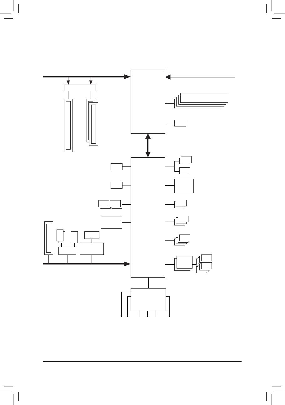
Z490 AORUS MASTER WF (Z490 AORUS MASTER WATERFORCE)
Motherboard Block Diagram
LGA1200 CPU
CPU CLK+/- (100~500 MHz)
DDR4 3200/3000/2933/2666/2400/2133 MHz
PCI Express 3.0 Bus
DMI 3.0
LAN
RJ45
Intel®
2.5GbE LAN
4 SATA 6Gb/s
(SATA3 0~3)
LPC
Bus
SPI
Bus
DDI
PCI Express 3.0 Bus
Center/Subwoofer
Speaker Out
Line Out
MIC
Line In
S/PDIF Out
Rear Speaker Out
CODEC
+
ESS ES9118 DAC
iTE®
Super I/O
8 USB 2.0/1.1
4 USB 3.2 Gen 1
2 USB Type-C™, with USB
3.2 Gen 2 support
3 USB 3.2 Gen 2
Type A
Intel® Z490
1 PCI Express x16
2 PCI Express x8
x4x4 x1
M2P_SB
M2A_CPU
HDMI 1.4
Switch
PCI Express x4
M2M_SB
SATA3
4/5
or
USB 2.0
Hub
Dual BIOS
TPM
Switch
x16x16
or
M.2 CNVi
WIFI

- 8 -

- 9 -
Hardware Installation
1-1 Installation Precautions
The motherboard contains numerous delicate electronic circuits and components which can become
damaged as a result of electrostatic discharge (ESD). Prior to installation, carefully read the user's
manual and follow these procedures:
•Prior to installation, make sure the chassis is suitable for the motherboard.
•Prior to installation, do not remove or break motherboard S/N (Serial Number) sticker or
warranty sticker provided by your dealer. These stickers are required for warranty validation.
•Always remove the AC power by unplugging the power cord from the power outlet before
installing or removing the motherboard or other hardware components.
•When connecting hardware components to the internal connectors on the motherboard, make
sure they are connected tightly and securely.
•When handling the motherboard, avoid touching any metal leads or connectors.
•It is best to wear an electrostatic discharge (ESD) wrist strap when handling electronic
components such as a motherboard, CPU or memory. If you do not have an ESD wrist strap,
keepyourhandsdryandrsttouchametalobjecttoeliminatestaticelectricity.
•Prior to installing the motherboard, please have it on top of an antistatic pad or within an
electrostatic shielding container.
•Before connecting or unplugging the power supply cable from the motherboard, make sure
the power supply has been turned off.
•Before turning on the power, make sure the power supply voltage has been set according to
the local voltage standard.
•Before using the product, please verify that all cables and power connectors of your hardware
components are connected.
•To prevent damage to the motherboard, do not allow screws to come in contact with the
motherboard circuit or its components.
•Make sure there are no leftover screws or metal components placed on the motherboard or
within the computer casing.
•Do not place the computer system on an uneven surface.
•Do not place the computer system in a high-temperature or wet environment.
•Turning on the computer power during the installation process can lead to damage to system
components as well as physical harm to the user.
•If you are uncertain about any installation steps or have a problem related to the use of the
product,pleaseconsultacertiedcomputertechnician.
•If you use an adapter, extension power cable, or power strip, ensure to consult with its installation
and/or grounding instructions.
Chapter 1 Hardware Installation
- 10 -
Hardware Installation
1-2 ProductSpecications
CPU Support for 10th Generation Intel® Core™ i9 processors/Intel® Core™ i7 processors/
Intel® Core™ i5 processors/Intel® Core™ i3 processors/Intel® Pentium® processors/
Intel® Celeron® processors in the LGA1200 package
(Go to GIGABYTE's website for the latest CPU support list.)
L3 cache varies with CPU
Chipset Intel® Z490 Express Chipset
Memory Intel® Core™ i9/i7 processors:
- Support for DDR4 3200/2933/2666/2400/2133 MHz memory modules
Intel® Core™ i5/i3/Pentium®/Celeron® processors:
- Support for DDR4 2666/2400/2133 MHz memory modules
4 x DDR4 DIMM sockets supporting up to 128 GB (32 GB single DIMM capacity)
of system memory
Dual channel memory architecture
Support for ECC Un-buffered DIMM 1Rx8/2Rx8 memory modules (operate in
non-ECC mode)
Support for non-ECC Un-buffered DIMM 1Rx8/2Rx8/1Rx16 memory modules
SupportforExtremeMemoryProle(XMP)memorymodules
(Go to GIGABYTE's website for the latest supported memory speeds and memory
modules.)
Onboard
Graphics
Integrated Graphics Processor-Intel® HD Graphics support:
- 1 x HDMI port, supporting a maximum resolution of 4096x2160@30 Hz
* Support for HDMI 1.4 version and HDCP 2.3.
Maximum shared memory of 512 MB
Audio Realtek® ALC1220-VB codec
* The front panel line out jack supports DSD audio.
ESS ES9118EQ DAC chip
Support for DTS:X® Ultra
HighDenitionAudio
2/4/5.1/7.1-channel
Support for S/PDIF Out
LAN Intel® 2.5GbE LAN chip (2.5 Gbit/1 Gbit/100 Mbit)
Wireless
Communication
Module
Intel® Wi-Fi 6 AX201
- WIFI a, b, g, n, ac with wave 2 features, ax, supporting 2.4/5 GHz Dual-Band
- BLUETOOTH 5.1
- Support for 11ax 160MHz wireless standard and up to 2.4 Gbps data rate
* Actual data rate may vary depending on environment and equipment.
Expansion Slots 1 x PCI Express x16 slot, running at x16 (PCIEX16)
* For optimum performance, if only one PCI Express graphics card is to be installed,
be sure to install it in the PCIEX16 slot.
1 x PCI Express x16 slot, running at x8 (PCIEX8)
* The PCIEX8 slot shares bandwidth with the PCIEX16 slot. When the PCIEX8 slot is
populated, the PCIEX16 slot operates at up to x8 mode.
1 x PCI Express x16 slot, running at x4 (PCIEX4)
(All of the PCI Express slots conform to PCI Express 3.0 standard.)
Multi-Graphics
Technology
Support for NVIDIA® Quad-GPU SLI™ and 2-Way NVIDIA® SLI™ technologies
Support for AMD Quad-GPU CrossFire™ and 2-Way AMD CrossFire™ technologies
- 11 -
Hardware Installation
Storage Interface 1 x M.2 connector (Socket 3, M key, type 2242/2260/2280/22110 PCIe x4/x2
SSD support) (M2P_SB)
1 x M.2 connector (Socket 3, M key, type 2242/2260/2280/22110 SATA and PCIe
x4/x2 SSD support) (M2A_CPU)
1 x M.2 connector (Socket 3, M key, type 2242/2260/2280/22110 SATA and PCIe
x4/x2 SSD support) (M2M_SB)
6 x SATA 6Gb/s connectors
Support for RAID 0, RAID 1, RAID 5, and RAID 10
* Refer to "1-9 Internal Connectors," for the installation notices for the M.2 and SATA
connectors.
Intel® Optane™ Memory Ready
USB Chipset:
- 2 x USB Type-C™ ports, with USB 3.2 Gen 2 support (1 port on the back panel,
1 port available through the internal USB header)
- 3 x USB 3.2 Gen 2 Type-A ports (red) on the back panel
- 4 x USB 3.2 Gen 1 ports (2 ports on the back panel, 2 ports available through
the internal USB header)
Chipset+2 USB 2.0 Hubs:
- 8 x USB 2.0/1.1 ports (4 ports on the back panel, 4 ports available through
the internal USB headers)
Internal
Connectors
1 x 24-pin ATX main power connector
2 x 8-pin ATX 12V power connectors
1 x CPU fan header
1 x water cooling CPU fan header
4 x system fan headers
2 x system fan/water cooling pump headers
2 x addressable LED strip headers
2 x RGB LED strip headers
3 x M.2 Socket 3 connectors
6 x SATA 6Gb/s connectors
1 x front panel header
1 x front panel audio header
1 x USB Type-C™ header, with USB 3.2 Gen 2 support
1 x USB 3.2 Gen 1 header
2 x USB 2.0/1.1 headers
1 x noise detection header
2 x Thunderbolt™ add-in card connectors
1 x Trusted Platform Module header (For the GC-TPM2.0 SPI/GC-TPM2.0 SPI
2.0 module only)
1 x power button
1 x reset button
2 x temperature sensor headers
1 x Clear CMOS jumper
2 x BIOS switches
- 12 -
Hardware Installation
Back Panel
Connectors
1 x Q-Flash Plus button
1 x Clear CMOS button
2 x SMA antenna connectors (2T2R)
1 x HDMI port
1 x USB Type-C™ port, with USB 3.2 Gen 2 support
3 x USB 3.2 Gen 2 Type-A ports (red)
2 x USB 3.2 Gen 1 ports
4 x USB 2.0/1.1 ports
1 x RJ-45 port
1 x optical S/PDIF Out connector
5 x audio jacks
I/O Controller iTE® I/O Controller Chip
Hardware
Monitor
Voltage detection
Temperature detection
Fan speed detection
Watercoolingowratedetection
Overheating warning
Fan fail warning
Fan speed control
* Whether the fan (pump) speed control function is supported will depend on the fan
(pump) you install.
Noise detection
BIOS 2x256Mbitash
Use of licensed AMI UEFI BIOS
Support for DualBIOS™
PnP 1.0a, DMI 2.7, WfM 2.0, SM BIOS 2.7, ACPI 5.0
Unique Features Support for APP Center
* Available applications in APP Center may vary by motherboard model. Supported
functionsofeachapplicationmayalsovarydependingonmotherboardspecications.
- @BIOS
- EasyTune
- Fast Boot
- Game Boost
- RGB Fusion
- Smart Backup
- System Information Viewer
- USB TurboCharger
Support for Q-Flash Plus
Support for Q-Flash
Support for Xpress Install
- 13 -
Hardware Installation
Please visit GIGABYTE's website
for support lists of CPU, memory
modules, SSDs, and M.2 devices.
Please visit the Support\Utility List
page on GIGABYTE's website to
download the latest version of apps.
Bundled
Software
Norton® Internet Security (OEM version)
cFosSpeed
XSplit Gamecaster + Broadcaster (12 months license)
Operating
System Support for Windows 10 64-bit
Form Factor ATX Form Factor; 30.5cm x 24.4cm
* GIGABYTEreservestherighttomakeanychangestotheproductspecicationsandproduct-relatedinformationwithout
prior notice.
- 14 -
Hardware Installation
1-3 Installing the CPU and CPU Cooler
Read the following guidelines before you begin to install the CPU:
•Make sure that the motherboard supports the CPU.
(Go to GIGABYTE's website for the latest CPU support list.)
•Always turn off the computer and unplug the power cord from the power outlet before installing the
CPU to prevent hardware damage.
•Locate the pin one of the CPU. The CPU cannot be inserted if oriented incorrectly. (Or you may
locate the notches on both sides of the CPU and alignment keys on the CPU socket.)
•Apply an even and thin layer of thermal grease on the surface of the CPU.
•Do not turn on the computer if the CPU cooler is not installed, otherwise overheating and damage
of the CPU may occur.
•SettheCPUhostfrequencyinaccordancewiththeCPUspecications.Itisnotrecommended
thatthesystembusfrequencybesetbeyondhardwarespecicationssinceitdoesnotmeetthe
standard requirements for the peripherals. If you wish to set the frequency beyond the standard
specications,pleasedosoaccordingtoyourhardwarespecicationsincludingtheCPU,graphics
card, memory, hard drive, etc.
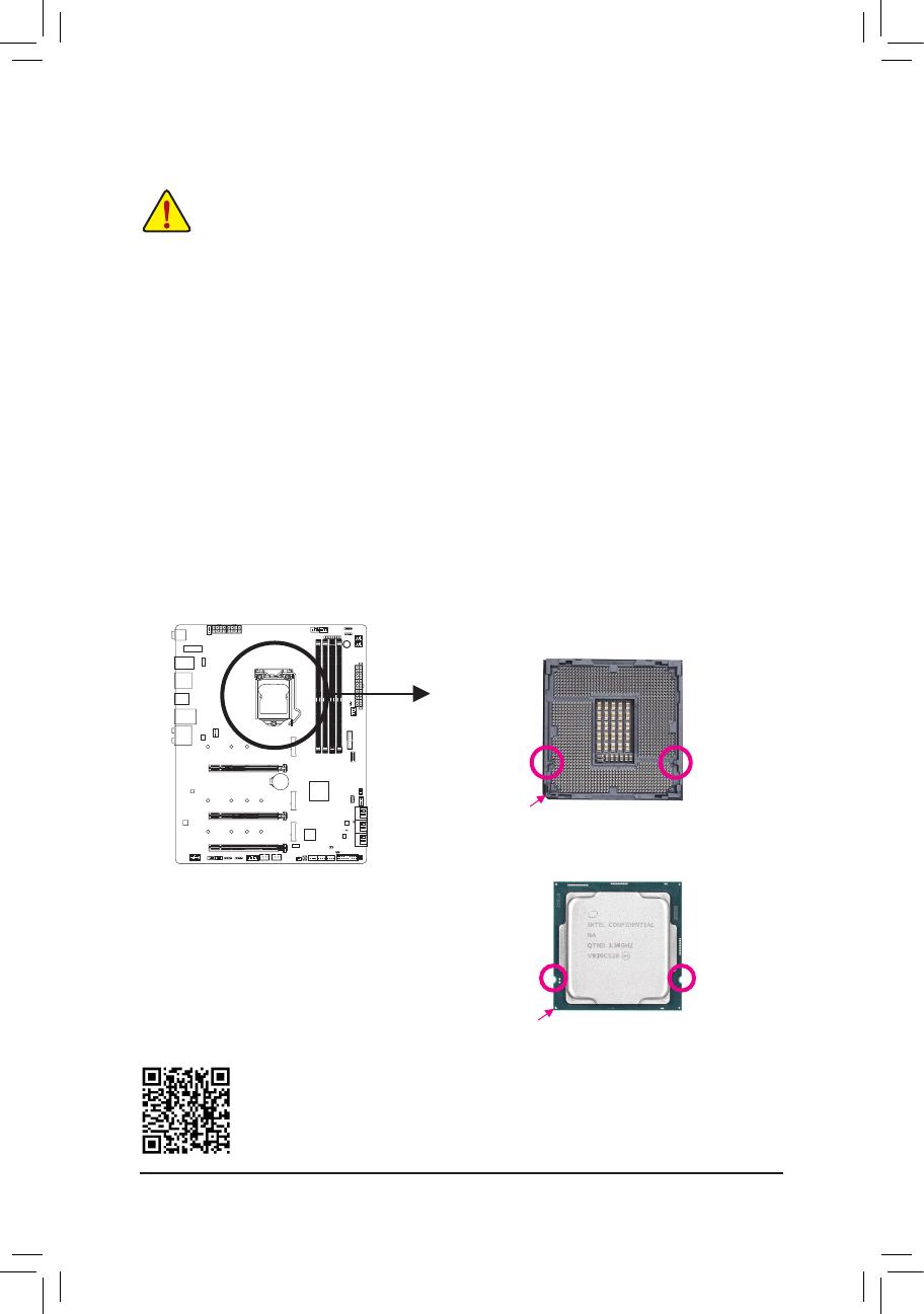
1-3-1 Installing the CPU
A. Locate the alignment keys on the motherboard CPU socket and the notches on the CPU.
Please visit GIGABYTE's website for details on hardware installation.
Triangle Pin One Marking on the CPU
NotchNotch
LGA1200 CPU
Alignment
Key
Alignment
Key
LGA1200 CPU Socket
Pin One Corner of the CPU Socket

- 15 -
Hardware Installation
B. Follow the steps below to correctly install the CPU into the motherboard CPU socket.
•Before installing the CPU, make sure to turn off the computer and unplug the power cord from
the power outlet to prevent damage to the CPU.
•To protect the socket contacts, do not remove the protective plastic cover unless the CPU is
inserted into the CPU socket. Save the cover properly and replace it if the CPU is removed.
Step 1:
Gently press the CPU socket lever handle down
andawayfromthesocketwithyournger.Then
completely lift the CPU socket lever and the metal
load plate/plastic cover will be lifted as well.
Step 2:
HoldtheCPUwithyourthumbandindexngers.
Align the CPU pin one marking (triangle) with the
pin one corner of the CPU socket (or you may align
the CPU notches with the socket alignment keys)
and gently insert the CPU into position.
Step 4:
Finally, secure the lever under its retention tab to
complete the installation of the CPU.
NOTE:
Hold the CPU socket lever by the handle, not the lever base portion.
Step 3:
Once the CPU is properly inserted, carefully
replace the load plate. When replacing the load
plate, make sure the front end of the load plate
is under the shoulder screw. Then press the CPU
socket lever. The protective plastic cover may
pop off from the load plate during the process of
engaging the lever. Remove the cover. (Save the
cover properly and always replace it when the
CPU is not installed.)
- 16 -
Hardware Installation
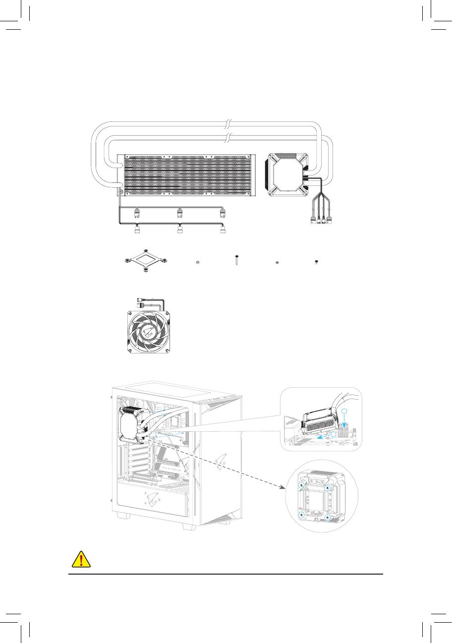
1-3-2 Installing the Water Cooling Kit
Refer to the following illustrations to install the Water Cooling Kit in the motherboard and chassis.
AORUS LIQUID COOLER VRM
Fan Washers Radiator WashersFan Screws
AORUS 120mm Fan
Backplate
Radiator Screws
Step 1:
BeforeinstallingtheWaterCoolingKit,removetheprotectiveplasticlmfromthebottom
oftheheatsinkrstandapplytheincludedthermalgreaseevenlyontotheCPUsurface.
The components of the Water Cooling Kit are as follows:
1
2
- 17 -
Hardware Installation
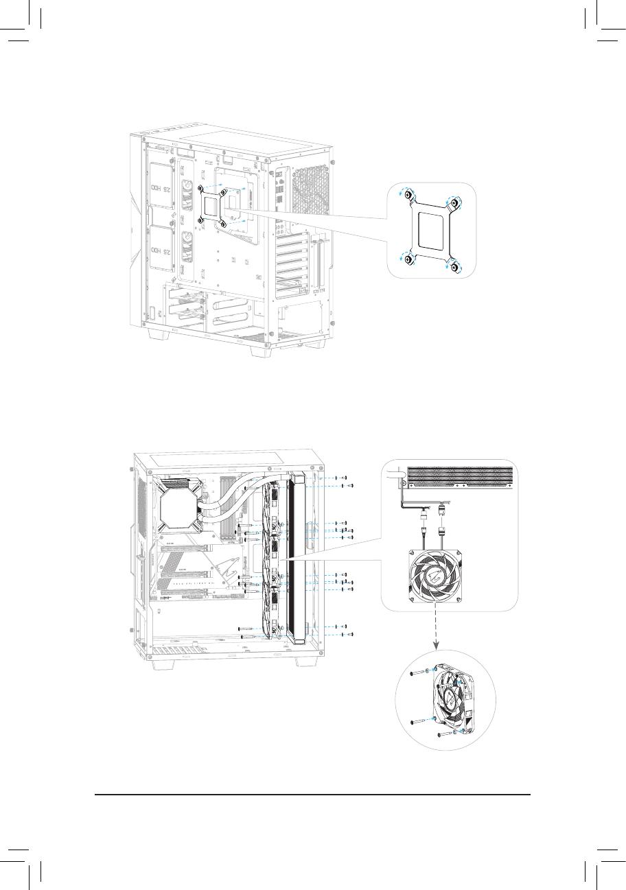
Step 2:
Step 3:
AORUS
120mm Fan *3
Fan LEDFan
- 18 -
Hardware Installation
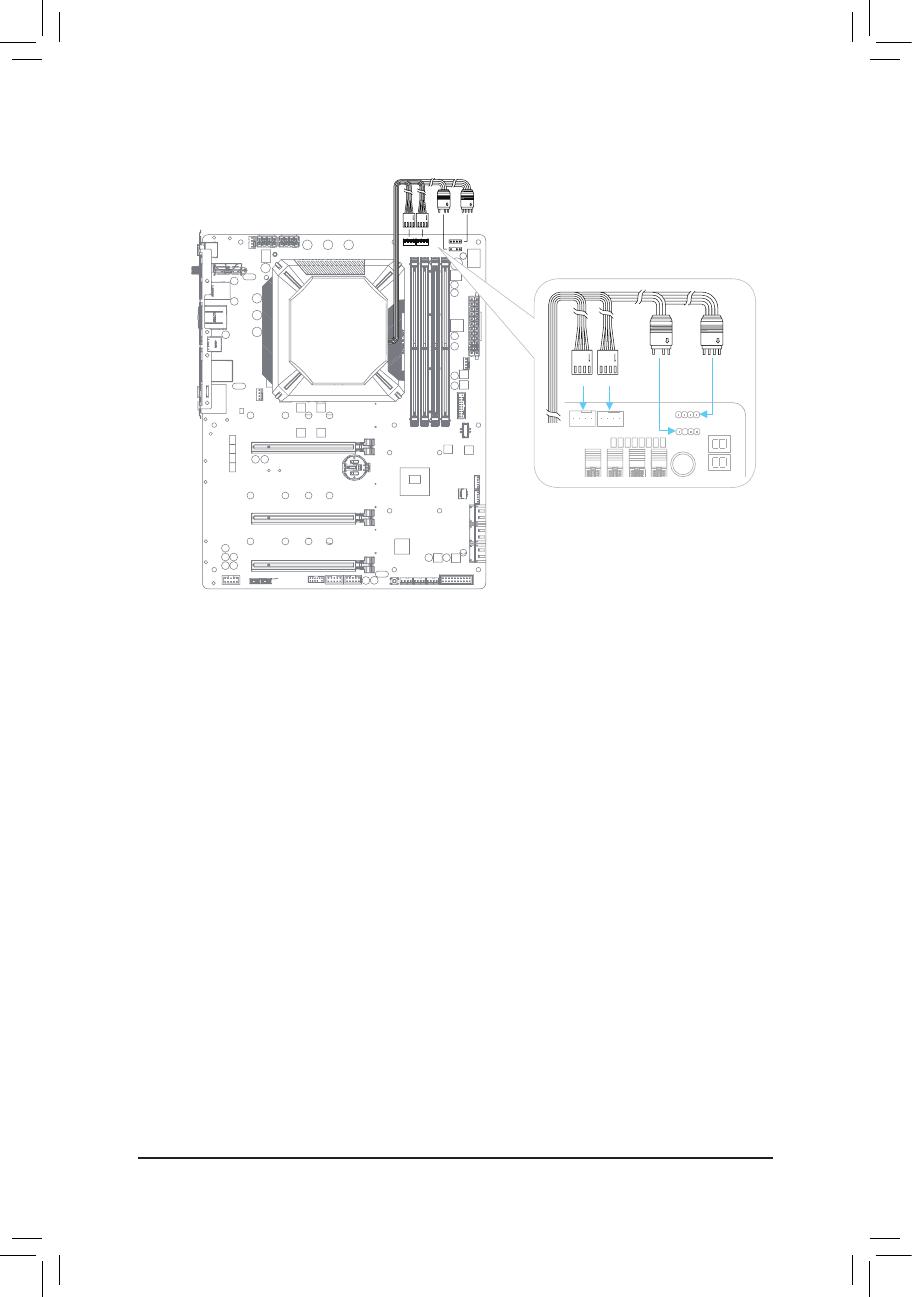
Step 4:
LED_C2
D_LED2
CPU_FANCPU_OPT
Cap LED
Fan LED
Pump Fan
- 19 -
Hardware Installation
1-4 Installing the Memory
Read the following guidelines before you begin to install the memory:
•Make sure that the motherboard supports the memory. It is recommended that memory of the same
capacity, brand, speed, and chips be used.
(Go to GIGABYTE's website for the latest supported memory speeds and memory modules.)
•Always turn off the computer and unplug the power cord from the power outlet before installing the
memory to prevent hardware damage.
•Memory modules have a foolproof design. A memory module can be installed in only one direction.
If you are unable to insert the memory, switch the direction.
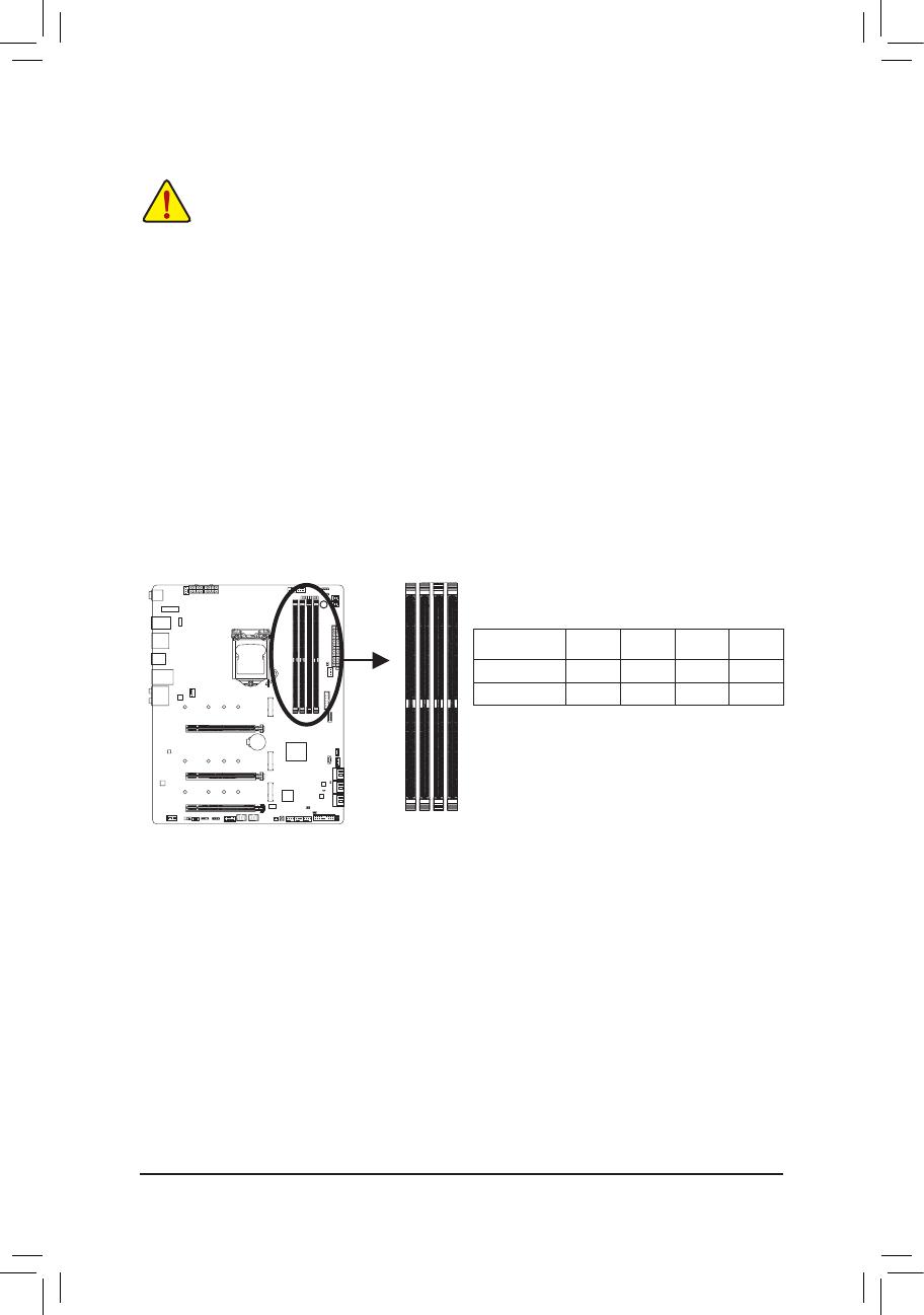
1-4-1 DualChannelMemoryConguration
This motherboard provides four memory sockets and supports Dual Channel Technology. After the memory
isinstalled,theBIOSwillautomaticallydetectthespecicationsandcapacityofthememory.EnablingDual
Channel memory mode will double the original memory bandwidth.
The four memory sockets are divided into two channels and each channel has two memory sockets as following:
Channel A: DDR4_A1, DDR4_A2
Channel B: DDR4_B1, DDR4_B2
RecommandedDualChannelMemoryConguration:
Due to CPU limitations, read the following guidelines before installing the memory in Dual Channel mode.
1. Dual Channel mode cannot be enabled if only one memory module is installed.
2. When enabling Dual Channel mode with two or four memory modules, it is recommended that memory
of the same capacity, brand, speed, and chips be used.
(SS=Single-Sided, DS=Double-Sided, "- -"=No Memory)
DDR4_A1 DDR4_A2 DDR4_B1 DDR4_B2
2 Modules - - DS/SS - - DS/SS
4 Modules DS/SS DS/SS DS/SS DS/SS
DDR4_A1
DDR4_A2
DDR4_B1
DDR4_B2
- 20 -
Hardware Installation
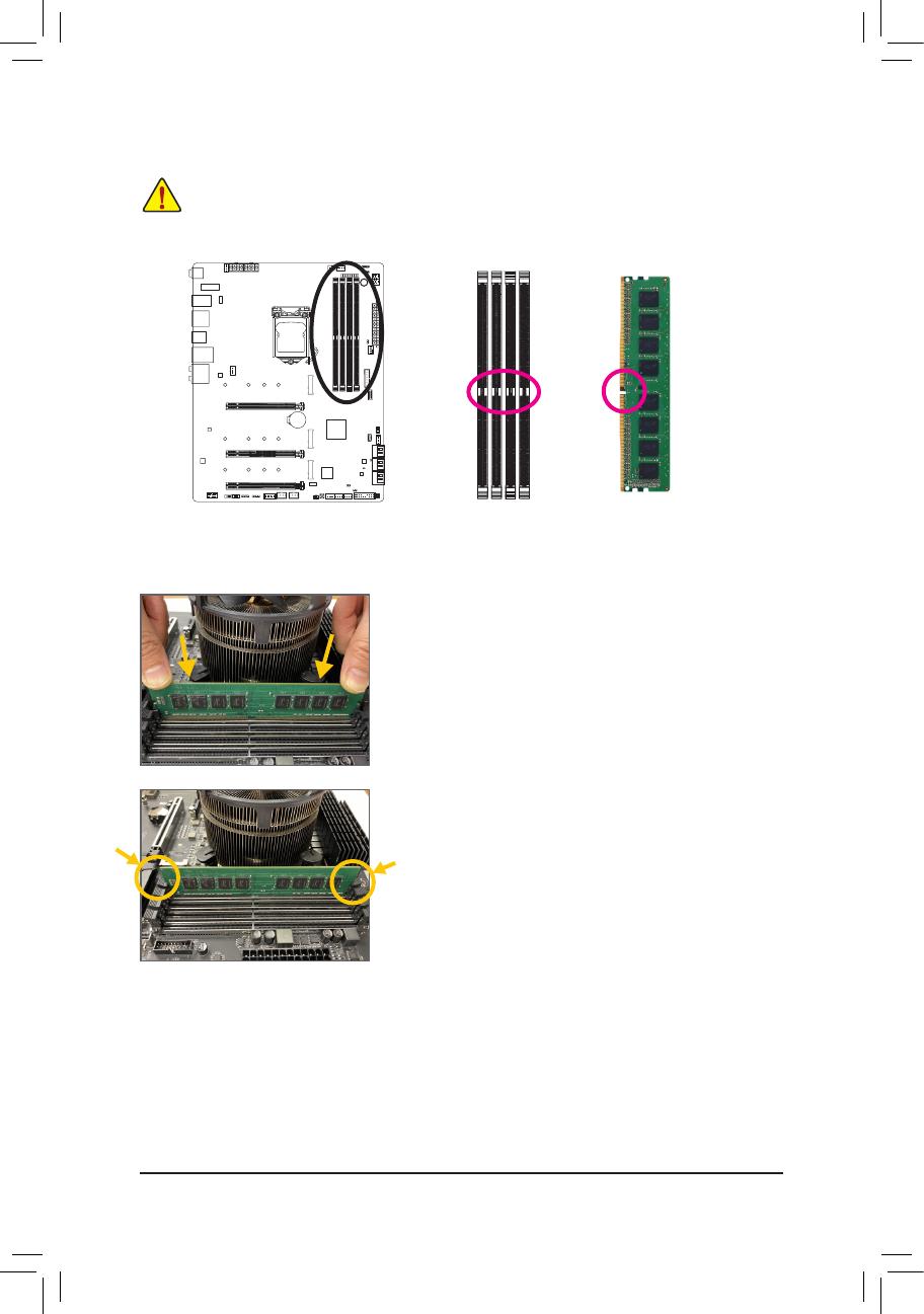
1-4-2 Installing a Memory
Before installing a memory module, make sure to turn off the computer and unplug the power cord
from the power outlet to prevent damage to the memory module. DDR4 and DDR3 DIMMs are not
compatible to each other or DDR2 DIMMs. Be sure to install DDR4 DIMMs on this motherboard.
Notch
DDR4 DIMM
ADDR4memorymodulehasanotch,soitcanonlytinonedirection.Followthestepsbelowtocorrectlyinstall
your memory modules in the memory sockets.
Step 1:
Note the orientation of the memory module. Spread the retaining clips
at both ends of the memory socket. Place the memory module on the
socket.Asindicatedinthepictureontheleft,placeyourngerson
the top edge of the memory, push down on the memory and insert it
vertically into the memory socket.
Step 2:
The clips at both ends of the socket will snap into place when the
memory module is securely inserted.
/