Page is loading ...

M10RDI
Intel Atom Mini ITX Motherboard
with Intel ICH10R Chipset
User’s Manual
1st Ed – 11 January 2013

M1
0
F
C
(2)
T
MA
Y
THI
FO
R
TH
E
A
G
A
CO
RA
D
A
C
C
IN
T
OP
E
INT
E
AT
H
N
o
Thi
s
det
a
C
o
Co
p
No
p
by
a
oft
h
Tr
a
Bra
n
2
M
0
RDI
C
C State
m
T
HISDEVIC
E
Y
CAUSEUN
I
S EQUIP
M
R
A CLAS
S
E
SE LIMIT
A
INST HA
R
MMERCI
A
D
IATE RA
D
C
ORDAN
C
T
ERFERE
N
E
RATIONOF
E
RFERENCE
H
ISOWNEX
o
tice
s
guideisde
a
iledinform
o
pyright
N
p
yright
2
p
artofthis
d
a
nymeans,
e
h
eoriginal
m
a
demar
k
n
dandpro
d
M
10RDI Us
e
m
ent
E
MUSTACC
DESIREDO
P
M
ENT HAS
S
"A" DIGI
T
S ARE DE
R
MFUL IN
T
A
L ENVIRO
D
IO FREQ
C
E WITH T
N
CE TO R
A
THISEQUI
P
INWHICH
C
PENSE.
signedfor
e
ation,plea
s
N
otice
2
013 Giga
b
d
ocument
m
e
lectronico
m
anufactur
e
k
Ackno
w
d
uctnames
a
e
r’s Manu
a
THIS DE
V
RULES.
O
FOLLO
W
(1) THIS
D
INTERF
E
EPTANYIN
T
P
ERATION.
BEEN TE
S
TA
L DEVI
C
S
IGNED T
T
ERFERE
N
NMENT.
T
UENCY E
N
HE INSTR
A
DIO COM
MENTINA
C
ASETHEU
S
e
xperienced
ealwaysre
f
b
yte Techn
o
m
ayberepr
o
r
mechanic
a
e
r.
w
ledgem
e
a
retradem
a
a
l
V
ICE COM
O
PERATI
O
W
ING TWO
D
EVICE M
E
RENCE.
T
ERFERENC
E
S
TED AN
D
C
E, PURS
U
T
O PROVI
D
N
CE WHE
T
HIS EQUI
P
N
ERGY A
N
UCTION
M
MUNICAT
I
RESIDENTI
A
S
ERWILLB
E
userstose
t
f
ertotheel
e
o
logy Inc.,
o
duced,co
p
a
l,foranyp
u
ent
a
rksorregis
t
PLIES WI
T
O
N IS SUB
J
CONDITI
O
AY NOT
C
E
RECEIVED
D
FOUND
T
U
ANT TO
P
D
E REASO
N THE EQ
P
MENT G
E
N
D, IF NO
T
M
ANUAL,
M
I
ONS.
A
LAREAISL
I
E
REQUIRED
t
upthesyst
e
e
ctronicus
e
ALL RIGH
T
p
ied,transla
t
u
rpose,wit
h
t
eredtrade
m
T
H PART 1
J
ECT TO
T
O
NS:
C
AUSE HA
R
INCLUDING
T
O COMP
L
P
ART 15 O
NABLE P
R
UIPMENT
E
NERATE
S
T
INSTALL
E
M
AY CAUS
I
KELYTOCA
TOCORREC
T
e
mwithint
h
e
r'smanual.
T
S RESE
R
t
ed,ortran
s
h
outthepri
o
m
arksofth
e
5 FCC
T
HE
R
MFUL
INTERFERE
L
Y WITH T
H
F THE FC
C
R
OTECTI
O
IS OPER
A
S
, USES,
A
E
D AND U
E HARMF
U
USEHARM
F
C
TTHEINTE
R
h
eshortest
t
R
VED.
s
mittedina
o
rwrittenp
e
irrespecti
v
NCETHAT
H
E LIMIT
S
C
RULES.
O
N
A
TED IN A
A
ND CAN
S
ED IN
U
L
F
UL
R
FERENCE
t
ime.For
n
yformor
ermission
v
eowners.
S

User’sManual
Disclaimer
GigabyteTechnologyInc.reservestherighttomakechanges,withoutnotice,toanyproduct,
includingcircuitsand/orsoftwaredescribedorcontainedinthismanualinordertoimprove
designand/orperformance.GigabyteTechnologyassumesnoresponsibilityorliabilityforthe
useofthedescribedproduct(s),conveysnolicenseortitleunderanypatent,copyright,or
masksworkrightstotheseproducts,andmakesnorepresentationsorwarrantiesthatthese
productsarefreefrompatent,copyright,ormaskworkrightinfringement,unlessotherwise
specified.Applicationsthataredescribedinthismanualareforillustrationpurposesonly.
GigabyteTechnologyInc.makesnorepresentationorwarrantythatsuchapplicationwillbe
suitableforthespecifiedusewithoutfurthertestingormodification.
Life Support Policy
Gigabyte Technology’s PRODUCTS ARE NOT FOR USE AS CRITICAL
COMPONENTS IN LIFE SUPPORT DEVICES OR SYSTEMS WITHOUT THE PRIOR
WRITTEN APPROVAL OF Gigabyte Technology Inc.
As used herein:
1. Life support devices or systems are devices or systems which, (a) are intended for
surgical implant into body, or (b) support or sustain life and whose failure to perform,
when properly used in accordance with instructions for use provided in the labeling, can
be reasonably expected to result in significant injury to the user.
2. A critical component is any component of a life support device or system whose failure
to perform can be reasonably expected to cause the failure of the life support device or
system, or to affect its safety or effectiveness.
A Message to the Customer
Gigabyte Customer Services
Each and every Gigabyte’s product is built to the most exacting specifications to ensure
reliable performance in the harsh and demanding conditions typical of industrial
environments. Whether your new Gigabyte device is destined for the laboratory or the
factory floor, you can be assured that your product will provide the reliability and ease of
operation for which the name Gigabyte has come to be known.
M10RDI User’s Manual 3

M10RDI
Your satisfaction is our primary concern. Here is a guide to Gigabyte’s customer services.
To ensure you get the full benefit of our services, please follow the instructions below
carefully.
Technical Support
We want you to get the maximum performance from your products. So if you run into
technical difficulties, we are here to help. For the most frequently asked questions, you
can easily find answers in your product documentation. These answers are normally a lot
more detailed than the ones we can give over the phone. So please consult the user’s
manual first.
To receive the latest version of the user’s manual; please visit our Web site at:
http://www.gigabyte.tw/
If you still cannot find the answer, gather all the information or questions that apply to
your problem, and with the product close at hand, call your dealer. Our dealers are well
trained and ready to give you the support you need to get the most from your Gigabyte’s
products. In fact, most problems reported are minor and are able to be easily solved over
the phone.
Inaddition,freetechnicalsupportisavailablefromGigabyte’sengineerseverybusinessday.We
arealwaysreadytogiveadviceonapplicationrequirementsorspecificinformationonthe
installationandoperationofanyofourproducts.Pleasedonothesitatetocallore‐mailus.
4 M10RDI User’s Manual

User’s Manual
Product Warranty
Gigabyte warrants to you, the original purchaser, that each of its products will be free
from defects in materials and workmanship for two years from the date of purchase.
This warranty does not apply to any products which have been repaired or altered by
persons other than repair personnel authorized by Gigabyte, or which have been subject
to misuse, abuse, accident or improper installation. Gigabyte assumes no liability under
the terms of this warranty as a consequence of such events. Because of Gigabyte’s high
quality-control standards and rigorous testing, most of our customers never need to use
our repair service. If any of Gigabyte’s products is defective, it will be repaired or
replaced at no charge during the warranty period. For out-of-warranty repairs, you will be
billed according to the cost of replacement materials, service time, and freight. Please
consult your dealer for more details. If you think you have a defective product, follow
these steps:
1. Collect all the information about the problem encountered. (For example, CPU type
and speed, Gigabyte’s products model name, hardware & BIOS revision number, other
hardware and software used, etc.) Note anything abnormal and list any on-screen
messages you get when the problem occurs.
2. Call your dealer and describe the problem. Please have your manual, product, and
any helpful information available.
3. If your product is diagnosed as defective, obtain an RMA (return material authorization)
number from your dealer. This allows us to process your good return more quickly.
4. Carefully pack the defective product, a complete Repair and Replacement Order Card
and a photocopy proof of purchase date (such as your sales receipt) in a shippable
container. A product returned without proof of the purchase date is not eligible for
warranty service.
5. Write the RMA number visibly on the outside of the package and ship it prepaid to your
dealer.
M10RDI User’s Manual 5

M10RDI
Content
1.Getting Started ........................................................................................................ 9
1.1 Safety Precautions ...................................................................................................9
1.2 Packing List ..............................................................................................................9
1.3 Document Amendment History ...............................................................................10
1.4 System Specifications .............................................................................................12
1.5 Architecture Overview – Block Diagram ..................................................................14
2. Hardware Configuration ........................................................................................ 15
2.1 Product Overview ....................................................................................................16
2.2 Before you Proceed ................................................................................................18
2.3 Motherboard Overview ............................................................................................19
2.3.1 Placement Direction ........................................................................................................ ……19
2.3.2 Screw Holes ......................................................................................................................... ...19
2.4 Setting Jumpers & Connectors ............................................................................... 23
2.4.1 Serial Port Setting - RS232/422/485 (JRS1, JRS2, JRS3, JRS4) ........................................... 23
2.4.2 Serial Port 1 Select - RS-232/422/485 (JCOM1) ......................................................................24
2.4.3 Serial Port 3 RI Pin Signal Select – Ring/+5V/+12V (JCOM3) .................................................25
2.4.4 Power Mode Select – AT or ATX (AT_CN) ........................................................................ …..26
2.4.5 Clear CMOS (CLR_CMOS) ..................................................................................................... 26
2.4.6 System Fan Connector (SYS_FAN) ........................................................................................ 27
2.4.7 Serial Port 3 Connector (COM3) .............................................................................................. 27
2.4.8 Serial Port 4 Connector (COM4) .............................................................................................. 28
2.4.9 Serial Port 5 Connector (COM5) ............................................................................................ ..28
2.4.10 Serial Port 5 Select - RS-232/422/485 (JCOM5) ................................................................... 29
2.4.11 Serial Port 6 Connector (COM6) ............................................................................................ 29
2.4.12 LVDS Connector (LVDS) ................................................................................................. …...30
2.4.13 LCD Inverter Connector (BKL_CN) ................................................................................... ….31
2.4.14 Front Panel Connector (F_PANEL) ................................................................................. ……31
2.4.15 Front Panel Audio Connector (F_AUDIO)........................................................................... …32
2.4.15.1 Signal Description – Audio connector (F_AUDIO) ......................................................... …..32
2.4.16 Audio Amplifier Connector (SPK_OUT) ..................................................................................33
2.4.17 SATA Power (SATAPW_1) ............................................................................................. ……33
2.4.18 SATA Power (SATAPW_2) ............................................................................................... ….34
6 M10RDI User’s Manual

User’s Manual
2.4.19 USB Connector (F_USB1) .................................................................................................... 34
2.4.20 USB Connector (F_USB2) ................................................................................................. ...35
2.4.21 GPIO Connector (GPIO_CNT) .............................................................................................. 35
2.4.22LowPinCountConnector(LPC).............................................................................................................36
3. BIOS Setup .............................................................................................................. 37
3.1 Introduction ............................................................................................................. 38
3.2 Starting Setup ......................................................................................................... 38
3.3 Using Setup ............................................................................................................ 39
3.4 Getting Help ............................................................................................................ 40
3.5 In Case of Problems ................................................................................................ 40
3.6 BIOS setup .............................................................................................................. 41
3.6.1 Main Menu ................................................................................................................................ 41
3.6.1.1 System Date .......................................................................................................................... 41
3.6.1.2 System Time .......................................................................................................................... 41
3.6.2 Advanced BIOS settings ....................................................................................................... ….42
3.6.2.1 ACPI Settings ........................................................................................................................ 42
3.6.2.2 S5 RTC Wake settings .......................................................................................................... 43
3.6.2.3 SATA Configuration ............................................................................................................... 43
3.6.2.3 SATA Configuration ............................................................................................................... 44
3.6.2.4 USB Configuration .....................................................................................................………...45
3.6.2.5 F81214 Second Super IO Configuration ............................................................................... 46
3.6.2.5.1 Serial Port 1 Configuration .................................................................................................. 46
3.6.2.5.2 Serial Port 2 Configuration .................................................................................................. 47
3.6.2.6 IT8783F Super IO Configuration ........................................................................................... .48
3.6.2.6.1 Serial Port 3 Configuration .................................................................................................. 49
3.6.2.6.2 Serial Port 4 Configuration .................................................................................................. 49
3.6.2.6.3 Serial Port 5 Configuration .................................................................................................. 50
3.6.2.6.4 Serial Port 6 Configuration .................................................................................................. 50
3.6.2.7 IT8783F H/W Monitor ............................................................................................................. 51
3.6.3 Advanced Chipset Features ............................................................................................... ……52
3.6.3.1 Intel IGD Configuration .......................................................................................................... 53
3.6.4 Boot settings ...................................................................................................................... ……54
3.6.5 Security................................................................................................................................. ….55
3.6.5.1 Administrator Password ......................................................................................................... 55
M10RDI User’s Manual 7

M10RDI
3.6.5.2 User Password ...................................................................................................................... 55
3.6.6 Save & Exit ............................................................................................................................. ..56
3.6.6.1 Save Changes and Exit ......................................................................................................... 56
3.6.6.2 Discard Changes and Exit ..................................................................................................... 57
3.6.6.3 Save Changes and Reset ...................................................................................................... 57
3.6.6.4 Discard Changes and Reset .................................................................................................. 57
3.6.6.5SaveChanges..........................................................................................................................................57
3.6.6.6 Discard Changes .................................................................................................................... 57
3.6.6.7 Restore Defaults ..................................................................................................................... 57
3.6.6.8 Save as user defaults ............................................................................................................. 57
3.6.6.9 Restore user defaults ............................................................................................................. 57
3.6.6.10 Boot override ............................................................................................................. ………57
4.MechanicalDrawing....................................................................................................…..58
8 M10RDI User’s Manual

1
.
1.1
Wa
r
Ca
u
Al
w
mo
t
ins
t
us
f
1.
2
Be
f
ma
t
1 x
1 x
1 x
2 x
2 x
1 x
.
Get
t
SafetyPr
e
r
ning!
u
tion!
w
ays note
t
t
herboard.
t
ructions in
f
or further
s
2
Packin
g
f
ore you be
t
erials hav
e
M10RDI
M
CD-ROM
c
COM cabl
e
SATA cab
l
SATA Po
w
I/O shield
t
ing
S
e
caution
s
t
hat impro
p
We sugge
s
any circu
m
s
upport.
g
List
gin installi
n
e
been shi
p
M
ini-ITX M
o
c
ontains O
S
e
l
e
w
er Cable
S
tart
e
A
lways c
o
chassis
w
connecti
o
compon
e
experien
c
chassis.
A
lways g
touching
sensitive
a ground
compon
e
bag whe
n
p
er disass
e
s
t not rem
o
m
stance. If
n
g your sin
g
p
ped:
o
therboard
S
drivers/
Q
e
d
ompletely
d
w
henever
y
o
ns while t
h
e
nts can b
e
c
ed electr
o
round you
r
the CPU c
to static el
ing wrist s
t
e
nts in a st
a
n
they are
n
e
mbling ac
t
o
ving the h
e
you really
h
gle board,
Q
IG/User’s
d
isconnect
y
ou work w
i
h
e power i
s
e
damaged
o
nics perso
r
self to re
m
ard. Mode
r
ectric char
g
t
rap at all ti
a
tic-dissip
a
n
ot in the
c
t
ion could
c
e
at sink wi
t
h
ave to do
please ma
Manual
the power
i
th the har
d
s
on. Sensi
t
by sudden
n
nel shoul
d
m
ove any st
r
n electroni
g
es. As a
s
m
es. Plac
e
tive surfac
e
c
hassis.
c
ause dam
a
t
hout corre
c
this, pleas
k
e sure th
a
M1
0
Us
e
cord from
d
ware. Do
n
tive electr
o
n
power su
r
d
open the
t
atic charg
e
i
c devices
a
s
afety prec
a
e
all electr
o
e or static-
s
a
ge to the
ct
e contact
a
t the follo
w
0
RDI User’
s
e
r’s Manua
l
your
n
ot make
o
nic
r
ges. Only
PC
e
before
a
re very
a
ution, use
o
nic
s
hielded
w
ing
s
Manual
9
l
9

M10RDI
1.3DocumentAmendmentHistoy
RevisionDateComment
1stJanuary2013InitialRelease
10 M10RDI User’s Manual

User’s Manual
This manual describes in detail the Gigabyte Technology M10RDI Single Board.
We have tried to include as much information as possible but we have not duplicated
information that is provided in the standard IBM Technical References, unless it proved
to be necessary to aid in the understanding of this board.
We strongly recommend that you study this manual carefully before attempting to
interface with M10RDI series or change the standard configurations. Whilst all the
necessary information is available in this manual we would recommend that unless you
are confident, you contact your supplier for guidance.
Please be aware that it is possible to create configurations within the CMOS RAM that
make booting impossible. If this should happen, clear the CMOS settings, (see the
description of the Jumper Settings for details).
If you have any suggestions or find any errors concerning this manual and want to inform
us of these, please contact our Customer Service department with the relevant details.
M10RDI User’s Manual 11

M10RDI
1.4SystemSpecifications
System Specifications
System
CPU Onboard Intel® Atom™ D2550(N2800/N2600 for Option)
BIOS AMI 16Mb SPI BIOS
System Chipset Intel® ICH10R
I/O Chip ITE8783+ FINTEK F81214
System Memory
2x 204-pin DDR3 SODIMM, up to 4GB
(N2600 support 1 x DDR3 SODIMM only)
Watchdog Timer H/W Reset : 1 to 255 sec/min per step (Option)
H/W Status Monitor
Monitoring temperature, voltage, and cooling fan status.
Auto throttling control when CPU overheats
TPM Infineon TPM1.2 SLB9635 (Optional)
Expansion
1x PCI
2 x mini-PCI-E connectors
Smart Fan Control Yes
Display
Chipset Cedarview Integrated graphics
Dual Display LVDS+VGA, VGA+HDMI, HDMI+LVDS
VGA
HDMI
Max resolution: 1920 x 1200
Max resolution: 1920 x 1200
LVDS
eDP to LVDS translator, Dual channel 18/24 bit
Max resolution: 1920 x 1080
LVDS Backlight Yes, through internal LVDS Backlight Connector
Audio
Audio Codec Azalia Realtek ALC269
Audio Interface Mic-In, Line-In and Line-Out, speaker out
Audio Amplifier(W) Build-in 2W Audio amplifier on chip
Ethernet
Chipset 2 x Realtek 8111E
Ethernet Interface 10/100/1000 Gigabit Ethernet Compatible
12 M10RDI User’s Manual

User’s Manual
M10RDI User’s Manual 13
I/O
MIO
2 External(COM1, RS-232/422/485; COM2, RS-232), 4 Internal
(COM3&5, RS-232 with 5V/12V selected by jumper, COM4&6,
RS-232), 4 SATA II, 1 HDMI, 1 VGA, 1 LVDS, 2 LAN, 1 PS/2
USB 8 USB2.0 ( 4 Rear , 4 internal )
Back Panel I/O Port
Back Panel I/O Port
1 DC-in Connector (4-pin)
1 VGA Port
1 HDMI Port
2 COM Ports
4 USB 2.0 Ports
2 LAN RJ45 Ports
1 Audio I/O (3 Jacks)
1 PS/2 Mini-Din (KB/MS support by external Y-cable)
Internal I/O Connector
Internal I/O Connector
2 USB Connectors each supports 2 USB Ports
4 COM RS-232 Connectors
4 SATA II Connectors, RAID 0,1,5,10 supported
2 SATA Power Connectors
1 Front Panel Connector
1 Front Audio Connector
1 System Fan Connector
1 GPIO Connector
1 Mini PCI-E Connector full size for mSATA (PCIe1X for Option)
1 Mini PCI-E Connector half size for PCIe slot
1 Speaker-out L/R Connector
1 LVDS Connector
1 LVDS Backlight Connector
1 LPC Connector
Power
Power Requirement DC 12V
Power Type AT / ATX mode (selectable by Jumper)
Power Connector
4-pin DC-in Power Connector,
4-pin ATX 12V Power Connector
Mechanical & Environmental
Operating Temperature 0°C to 60°C (32°F to 140°F)
Operating Humidity 0% to 90% relative humidity, non-condensing
Size 6.69" x 6.69" (170 x 170 mm)
Weight 0.77 Ibs (0.35 Kg)
M1
0
1.5
The
14
M
0
RDI
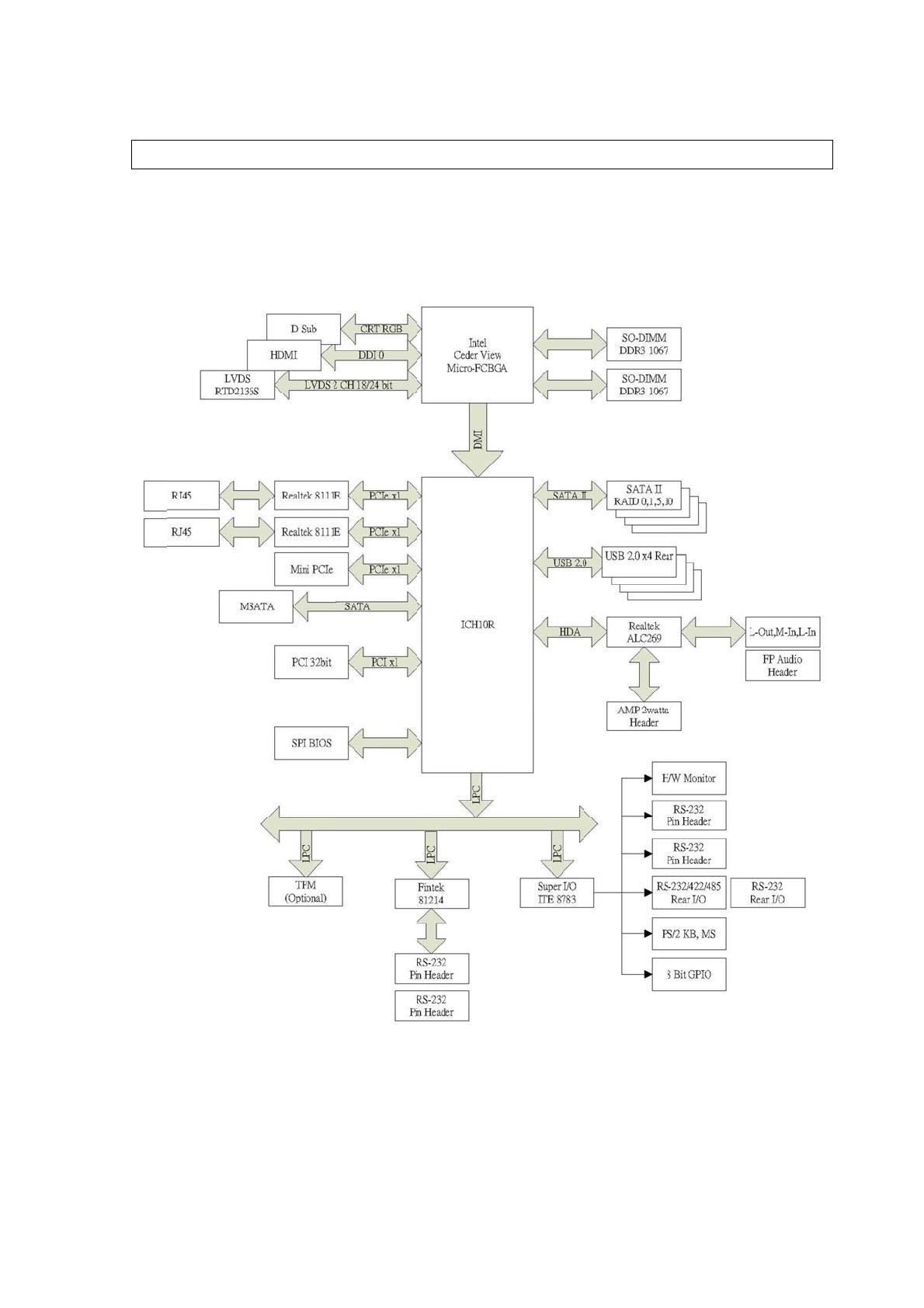
Architec
t
followingb
M
10RDI U
s
t
ureOver
v
lockdiagra
m
s
er’s Man
u
v
iew–Bl
o
m
showsth
e
u
al
o
ckDiagr
a
e
architectu
r
a
m
r
eandmain componen
t
t
sofM10R
D
D
I

User’s Manual
2.Hardware
Configuration
M10RDI User’s Manual 15

M10RDI
2.1ProductOverview
M10RDI is designed to unleash the power of the new Intel® Atom™ processor D2000 /
N2000 which supports the new revolutionary two–chip layout. The Intel® Cedarview
processor also provides additional flexibility and upgradeability with two slots of single
channel DDR3 memory at 1066 MHz supporting up to 4GB maximum.
2. With breakthrough low-power silicon, M10RDI can be used with a passive thermal
solution based on the recommended boundary conditions.1
3. M10RDI represents a fundamental shift in system design—small, yet powerful enough
to enable a big Internet experience for all audiences.
2.1.1 Platform Features and Benefits
• DirectX® 10.1 let you enjoy awesome graphics performance, stunning 3D visual effect
and dynamic interactivity
• Memory support, integrated DDR3 memory controller
• Operating system support:
- Microsoft Windows XP 32/64bit
‐MicrosoftWindows732/64bit
2.1.2 Key Architecture Features
• Supports Intel® Atom™ processor D2000 / N2000.series
- Supports 2 lanes in each direction for N2000 processor and 4 lanes in each direction
for D2000 processor (Gen 1 2.5gbps) per lane per direction point- to- point DMI interface.
- Compatible with high speed DDR3-1066MHz
-TDP: 16W
•Intel® HD Audio Technology
• Integrated Display Interfaces
- HDMI
- VGA
- Dual Channel LVDS
• Doubles the transfer speed of SATA, running at speed up to 3.0Gb/s
• Provides 10/100/1000 Mbps solution to your network or broadband connection without
having to buy an
•OnboardaudioCODECsupportsuncompromisingDVDaudioquality,bringingamovevivid
soundexperienceandhigh‐qualityaudiowithouthavingtobuyadvancedsoundcards.
16 M10RDI User’s Manual

• M
a
M1
0
SO
D
*S
O
No
t
(1)
sys
t
(2)
bo
a
ele
c
(3)
T
the
Her
e
a
in Memo
r
0
RDI provi
d
DIMM onl
y
O
DIMM mo
t
e:
Please do
tem’s perf
o
Static elec
t
a
rds. Befor
e
c
tricity by t
o
The Platfo
r
far end fro
e
,SODIMM
2
r
y
d
es 2x 20
4
y
).
dule.
not chang
e
o
rmance w
i
t
ricity can
d
e
starting t
h
o
uching a
g
r
m require
s
m the pro
c
2
issituate
d
4
-pin DDR
3
e
any DDR
i
thout acq
u
d
amage th
e
h
ese proc
e
g
rounded
m
s
DDR3 S
O
c
essor.
d
atthefar
e
3
SODIMM
,
SDRAM p
u
iring tech
n
e
electroni
c
e
dures, en
s
m
etal obje
c
O
DIMMs to
e
ndfromth
e
,
up to 4G
B
arameter i
n
n
ical inform
a
c
compone
s
ure that y
o
c
t briefly.
be popula
t
e
processor.
B
(N2600 s
u
n
BIOS set
a
tion in ad
v
n
ts of the
c
o
u are disc
h
t
ed startin
g
M10
R
Us
e
u
pport 1 x
t
up to incre
v
ance.
c
omputer o
h
arged of
s
g
with the
S
R
DI User’s
e
r’s Manua
l
DDR3
ase your
r optional
s
tatic
S
ODIMM a
t
Manual 1
7
l
t
7

M1
0
• I/
O
- O
n
- T
w
- F
o
- T
w
- Hi
- U
S
- H
a
Fan
2.2
Tak
e
any
18
M
0
RDI
O
n
e PCI slo
t
w
o Mini-P
C
o
ur SATA2
w
o 10/100/
gh Definiti
o
S
B: USB 2
a
rdware M
o
control(Vo
Beforey
o
e
noteofth
e
motherboa
M
10RDI U
s
t
C
Ie sockets
ports
1000 Mbp
s
o
n Audio
.0/1.1, up t
o
nitor
ltage,Temp
o
uProce
e
e
following
p
rdsettings.
U
co
m
U
a m
e
co
m
H
the
m
W
anti
-
B
A
T
X
fro
m
da
m
s
er’s Man
u
s
Ethernet
C
o
8 ports
)
e
d
p
recautions
U
nplug the
p
m
ponent.
U
se a grou
n
e
tal object,
m
ponents t
o
H
old comp
o
m
.
W
henever
y
-
static pad
efore you i
X
power su
p
m
the powe
r
m
age to the
u
al
C
ontroller
beforeyou
p
ower cor
d
n
ded wrist
s
such as t
h
o
avoid da
m
o
nents by t
h
y
ou uninst
a
or in the b
a
nstall or re
p
ply is swi
t
r
supply. F
a
motherbo
a
installmot
h
d
from the
w
s
trap or to
u
h
e power s
u
m
aging the
m
h
e edges t
o
a
ll any com
p
a
g that ca
m
move any
c
ched off o
r
a
ilure to d
o
a
rd, periph
e
h
erboardco
w
all socket
u
ch a safel
y
u
pply case
m
due to st
o
avoid tou
p
onent, pl
a
m
e with the
c
omponen
t
r
the powe
r
o
so may c
a
e
rals, and/
o
mponents
o
before tou
c
y
grounded
, before h
a
t
atic electri
c
u
ching the I
a
ce it on a
g
compone
n
t
, ensure t
h
r
cord is de
a
use seve
r
o
r compon
o
rchange
c
hing any
object or
a
ndling
c
ity
Cs on
g
rounded
n
t.
h
at the
tached
r
e
e
nts.

2.3
Bef
o
mo
t
2.3
.
Wh
cor
r
indi
2.3
.
Pla
c
cha
s
Mother
b
o
reyouinst
a
t
herboardfi
.
1 Placem
e
en installin
r
ect orient
a
cated in th
.
2 Screw
H
c
efour(4)s
c
s
sis.
b
oardOv
e
a
llthemot
h
tsintoit.R
e
M
r
e
p
e
nt Directi
g the mot
h
a
tion. The
e
e image b
e
H
oles
c
rewsintot
h
D
m
rview
h
erboard,st
u
e
fertothec
h
M
ake sure t
e
moving th
hysical inj
u
on
erboard,
m
e
dge with
e
e
low.
h
eholesin
d
D
o not over
m
otherboar
d
u
dythecon
hassisdocu
m
t
o unplug t
h
e motherb
o
u
ry and da
m
m
ake sure t
e
xternal po
r
d
icatedbyci
tighten th
e
d
.
figurationo
m
entation
b
h
e power c
o
o
ard. Failu
r
m
age moth
hat you pl
a
r
ts goes to
rclestosec
u
e
screws!
D
fyourchas
s
b
eforeinstal
o
rd before
r
e to do so
erboard c
o
a
ce it into t
h
the rear p
a
u
rethemot
h
Place thi
s
rear of th
e
M10
R
D
oing so c
a
Us
e
s
istoensur
e
lingthemo
t
installing
o
can caus
e
o
mponents
h
e chassis
a
rt of the c
h
herboardt
o
s
side towa
e
chassis.
R
DI User’s
a
n damage
e
r’s Manua
l
e
thatthe
t
herboard.
o
r
e
you
.
in the
h
assis as
o
the
rds the
Manual 1
9
the
l
9

M10RDI
20 M10RDI User’s Manual
/