Page is loading ...

System Setup Connections and
Scheduled Maintenance Guide
for VacStar Models
VS20 VS40
All VS20 VacStars are wired directly via an electrical
(Handy) box that complies with local electrical codes
to the VacStar’s Electrical Junction Box.
The VS20 VacStar can be configured to run on 220
or 120 VAC. It comes configured to run on 220 VAC.
All VS40 VacStars are wired with a supplied hospital
grade NEMA 6-15P line cord and requires a hospital
grade 6-15R receptacle.
The VS40 VacStar runs on 220 VAC only.
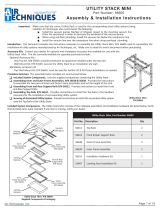
Use 18 Gauge, 4 Conductor, Interconnect Cable
Between VacStar Pump and Remote Switch
Interior Electrical
Box Connections
Vacuum Pump
Yellow 2
Brown 4
Interconnect Cable
Orange 3
Remote Switch
2
4
3
for Future Use
2
Yel
4
Brn
3
Org
Connection to 24V Switch Only Connection without
24V Switch
24V CONNECTIONS
VS20 120 or 220V Connections
For 120 V, change by placing
Jumper Tabs in position shown
220 V, factory set Jumper Tabs
position shown below
1 - 2 3 - 4 5 6 - 7
1 2 - 3 4 5 - 6 7
Internal Dual Voltage JumpersHandy Box Connection
4 inch Handy box (not supplied)
hardwired for VS20 units.
Green
Black
White
Installation -
Place VacStar in prepared utility site.
Connect the operatory main line to the Intake Solids Collector inlet port.
Connect the exhaust port of the VacStar to the facility drain
Connect facility water to the push to connect Water Inlet Connector.
If installing a 24V remote switch, refer to the 24V connections of this guide.
Connect VacStar to the appropriate facility power.
VacStar Documentation - Refer to the following VacStar documentation as necessary for more detailed
information on the plumbing, electrical connections and site requirements.
User’s Manual, P/N 55151CUL.
Pre-Installation Guide for Models VS20 and VS40, P/N 55341.
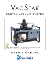
IMPORTANT
Add service disconnect if Power Supply Panel is
not located in equipment room.
6-15 R NEMA outlet to connect via the
supplied line cord for VS40 units.
Building Power Supply Panel
(Should be located in equipment room.)
Buck/Boost
Transformer
(Optional)
VS40 220V Connections
VS40
ELECTRICAL CONNECTIONS
Important -
Make sure to install the system in accordance with all local electrical and plumbing codes.
Make sure to efficiently use space by making connections as short and direct as possible to meet your
particular site requirements.
Make sure that all hose connections are straight and secure without any sharp bends or kinks.
Since the vacuum hose is rigid, make sure not to stress connections especially at the pump inlet.
VS20
Introduction - This document provides the instructions necessary to install the VacStar Models VS20 and VS40 system into a utility
room that is properly prepared for the system to be installed. This means that all site requirements have been met with plumbing
and electrical systems in place prior to making the installation.
20
DENTAL VACUUM SYSTEMS

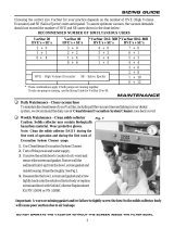
Routine Inspection - Monthly
1. Check tubing for kinks or cracks.
2. Check for abnormal noises and leaks.
3. Check exterior surfaces for dirt and debris, clean if necessary.
4. Checkthatnoammable,corrosive,orcombustiblematerialsarestoredin
the equipment room (especially in the area around the equipment).
5. Refertotherightandcheckthevacuumreliefvalvelter,cleanif
necessary.
Daily Maintenance - Clean vacuum lines
Flush all vacuum lines and tubing in the dental system with Monarch CleanStream Evacuation System Cleaner.
Vacuum Relief
Valve Filter
Intake Solids Collector Replacement - Monthly
1. Turn off the power and water supply.
2. Unscrew the solids bowl (counter clock-wise) and seal with the provided
Disposal Cap. Dispose of used Solids Collector.
3. Assemble a new bowl, screen and gasket included in the Solids Collector
Replacement Kit. 55880 (55880C case of 12 kits).
4. Install the new solids collector by screwing the bowl into the solids
collector body.
Intake Solids
Collector
NEVER OPERATE
WITHOUT THE SCREEN
INSTALLED IN THE BOWL
Water System
Assembly
Check/Clean Solenoid Water Inlet Strainer - Semi-Annually
1. Turn off the power and water supply to the equipment.
2. Use a wrench to unscrew (counter clockwise) the cover nut.
3. Remove the cover nut and strainer.
4. Inspect the strainer and clean as necessary.
Assembling the Water Inlet Strainer
1. Orienting the assembly with the cover nut facing down as shown,
seat strainer into the cover nut.
2. Insert the strainer up into the strainer body and tighten the cover nut.
3. Make sure the strainer stays perpendicular to the strainer body.
4. Push up and tighten the cover nut making sure not over tighten.
Strainer
Body
Flow
Direction
Arrow
Mesh
Strainer
Cover
Nut
Water Inlet Strainer
PLUMBING INSTALLATION
SCHEDULED MAINTENANCE
Water Inlet
Strainer
Vacuum
Breaker
Nipple
Solenoid
© 2014 Air Techniques, Inc. • P/N 55013, Rev. B • December 2018
Corporate Headquarters
1295 Walt Whitman Road
Melville, New York 11747- 3062, USA
Phone: 1-800-247-8324 Fax: 1-888-247-8481
www.airtechniques.com
Overhead
Connection
Sub Floor Connection
From Operatory
IN
OUT
Water Inlet
Connection
IN
OUT
Water Inlet
Connection
From Operatory
DRAIN OPTIONS
Indirect connec-
tion (Air gap) with
a p-trap.
OPEN
DRAIN PIPE
CLOSED
VENTED
DRAIN
Direct connection to
vented drain. No traps
before vent.
6”
1-1/2 Inch
P-Trap
OR
Intake
Solids
Collector
Electrical
Junction Box
Exhaust
to Drain
Push To
Connect
Water Inlet
Connector
Main Circuit
Breaker
ON/OFF Switch
24V
Remote
Wiring
Low Voltage
Circuit Breaker
Intake
Connection
From
Operatory
Power Cable,
(VacStar 20 only.)
/