Page is loading ...

• Programmable Feed Delay Settings: Prevents over filling by
allowing time for condensate to return to the boiler before initiating a
feed cycle.
• Programmable Feed Amount Settings: Includes one setting to raise
the water level to the boiler control and five additional settings to raise
the water level above the boiler control.
• LED Status Indicator: Displays mode of operation. Also provides
timer for convenient set-up of programmable feed amount setting.
• Manual Feed Button: Allows for manual feeds with the touch of a
button.
• Lock-Out Flood Protection: Locks out after sustained 10 minute feed
cycle to prevent flooding.
• Water Meter: Heavy duty meter tracks make-up water added to
system. (Not included with Model VXTC-WF).
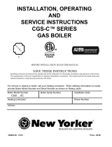
MODEL VXTC
Programmable
Water Feeder for
Commercial Boilers
120 VAC Operating Voltage
COMMERCIAL
A
B
C
D
D
E
F
VXTC COMPONENTS
A 3/4" NPT “Y” strainer
B 10 GPM flow restrictor
C 3/4" NPT solenoid valve
D (2) 3/4" NPT brass adapters with
connection gaskets
E Heavy-duty water meter
F VXTC controller
Be sure flow arrows on solenoid, meter
and strainer are aligned correctly. Use
teflon tape between meter and solenoid
to prevent leakage.
INSTALLATION
WARNING Frozen pipes/water damage. Central heating systems are prone to shut down as a result of power or fuel outages,
safety related fault conditions or equipment failure. Installation of freeze protection monitoring or other precautions is recom-
mended for unattended dwellings in climates subject to sustain below-freezing temperatures.
WARNING Electrical shock hazard. To prevent electrical shock, dea th or equipment damage, disconnect power supply before installing
or servicing control. Only qualified personnel may install or service this control in accordance with local codes and ordinances.
Read instructions completely before proceeding.
Prior to piping, remove the solenoid
valve from the VXTC control housing.
The VXTC is designed for the installation in 3/4" NPT black iron or steel piping. For servicing of the
control, the VXTC should be installed with unions and a bypass. The bypass should be construct-
ed so that all water added to the boiler is metered.
1 2
1

WIRING
G H P P FE A V
120 VAC 60 HZ
INCOMING
POWER
NEUTRAL HOT
1 2 3 4
120 VAC 60 HZ
INCOMING
POWER
NEUTRAL
HOT
2 1 P P A
120 VAC 60 HZ
INCOMING
POWER
NEUTRAL
JUMPER
HOT
NEUTRAL
HOT
BCOM
BNC
BNO
PCOM
PNC
PNO
C
H
120 VAC 60 HZ
BURNER CIRCUIT
120 VAC 60 HZ
INCOMING
POWER
NEUTRAL
HOT
3 4
1 2
NEUTRAL
HOT
3 4
1 2
C N.O N.C.
120 VAC 60 HZ
INCOMING
POWER
LWCO
NEUTRALHOT
1 2 3 4 5 6
120 VAC 60 HZ
INCOMING
POWER
NEUTRAL
HOT
1 2 3 4 5 6
120 VAC 60 HZ
INCOMING
POWER
NEUTRAL
HOT
SAFGARD MODELS 250, 250M, 250WC, 250MWC
MCDONNELL & MILLER MODELS 67, 67S, 63
MCDONNELL & MILLER MODELS 150, 157 MCDONNELL & MILLER MODELS 150E, 157E
MCDONNELL & MILLER MODELS 159, 159S
MCDONNELL & MILLER MODELS 47-2, 51-2
SAFGARD MODELS 450, CG450, CGT450
Powered by burner circuit
WITH JUMPER
NOTE: 47 or 51-2 should
not be connected to water
supply and should be used
as a signaling device only.
Powered by separate power source
WITHOUT JUMPER
VXT USED AS SECONDARY FEED DEVICE
(PUMP BACK-UP)
VXT USED AS PRIMARY FEED DEVICE
2

POWER THE CONTROL
SELECT FEED DELAY
SELECT FEED AMOUNT
DIAGNOSTIC SYMBOLS
Fd
001
dL
y
Err
LOC
–––
The Diagnostic LED indicate mode of operation and can be used to troubleshoot programming errors. See
figures below for diagnostic symbol interpretations.
NORMAL OPERATING MODE
Feeder is powered and on standby.
DELAY BEFOR FEED MODE
Allows for condensate to return
prior to feed (45 sec. to 10 min.).
FEED MODE
Solenoid valve is open.
TIMER
Counts seconds when FEED button is
pressed. Useful for selecting feed setting.
ERROR
Improper dipswitch setting. Check that ONE
Delay and ONE Feed switch is selected.
LOCKOUT MODE
Feeder has fed 10 minutes and continues to
receive a call from the boiler control. Check
operation of boiler control. Reset feeder by
removing power momentarily.
FEED CALL Illuminated decimal indicates feeder is receiving a call from the boiler control.
NO DELAY 45 SECONDS 2 MINUTES
(Factory Setting)
5 MINUTES 8 MINUTES 10 MINUTES
LWCO
(Factory Setting)
LWCO +15 SEC. LWCO +30 SEC. LWCO +60 SEC. LWCO +90 SEC. LWCO +120 SEC.
Once the control is plumbed and wired, power the system. Upon initial power up, the control will go through a 10
second self-diagnostic test cycle. During this period various characters will be displayed on the LED screen and the
solenoid will power up for approximately one second. This only takes place upon powering the control.
The VXTC is equipped with six delay before feed settings. The delay prevents over-feeding the boiler by allowing
time for condensate to return to the boiler prior to the initiation of a feed cycle. The VXTC is factory set with a two
minute delay. Longer delays should be selected for systems with slow condensate return. A NO DELAY setting is
also provided for process steam applications or other systems in which no delay is needed
The VXTC is equipped with six feed setting. The feeder is factory set in the LWCO position. In this setting, the VXTC
will stop feeding as soon as the water level satisfies the boiler control. The remaining five settings raise the water lev-
el above the boiler control by continuing the feed cycle for varying times (15 to 120 seconds) after the water satisfies
the boiler control. For information on proper feed setting procedure see section on page 4.
3

126 Bailey Road • North Haven, CT 06473 • (203) 776-0473 • FAX (203) 764-1711 • www.hydrolevel.com
LIMITED MANUFACTURER’S WARRANTY
We warrant products manufactured by Hydrolevel Company to be free from defects
in material and workmanship for a period of two years from the date of manufacture
or one year from the date of installation, whichever occurs first. In the event of any
claim under this warranty or otherwise with respect to our products which is made
within such period, we will, at our option, repair or replace such products or refund
the purchase price paid to us by you for such products. In no event shall Hydrolevel
Company be liable for any other loss or damage, whether direct, indirect, incidental
or consequential. This warranty is your EXCLUSIVE remedy and shall be IN PLACE OF
any other warranty or guarantee, express or implied, including, without limitation, any
warranty of MERCHANTABILITY or fitness for a particular purpose. This warranty may
not be assigned or transferred and any unauthorized transfer or assignment thereof
shall be void and of no force or effect.
DETERMINING PROPER FEED SETTINGS
SPECIFICATIONS
OPERATING TEST AND MAINTENANCE
To determine the proper feed setting follow these steps:
1. With the feeder in the “LWCO” position, power-up the system and set the thermostat
so there is no call for heat. Open the boiler drain and slowly lower the water level
until the boiler control calls for a feed. Stop draining the water and allow the VXTC to
raise the water level in the boiler. Check the water level following the feed cycle.
2. If the VXTC raised the water level to the normal operating range, the “LWCO” setting
should not be changed.
3. If the water level is below the normal operating range, push and hold the FEED
button on top of the VXTC until the water level reaches the optimum level. While
you are holding the FEED button, the diagnostic LED on the VXTC will function as
a stopwatch, continuing the number of seconds the FEED button is pressed. Use
the number displayed by the LED to select the proper feed amount setting, round-
ing up or down as necessary. For example, if the LED reads 28 seconds, select the
“LWCO+30” setting.
FLOW CURVE
At least once a year, after selecting delay and feed settings, test the VXTC by opening the boiler drain until the boiler
control calls for a feed. The feeder should go into either its delay mode (reading dLY on the LED) or will begin to feed
immediately depending on the setting. After the feed cycle, check the water level in the boiler. If the VXTC does not
raise the water to the desired level, repeat steps 1 through 3 in the section above. The Y strainer should be inspected
and cleaned annually.
070518
NOTE: Once the feed button returns to
the “off” position, the number displayed
on the LED will remain illuminated for
10 seconds. The LED will then revert to
normal operating display.
Max Fluid Temperature 100° F
Max Flow Rate 100 GPM @ 40 PSI
Maximum Single Cycle Feed 10 minutes @ 10 gpm = 100 gal.
Electrical 120 VAC – 60 HZ
4
/