Page is loading ...

Read and understand these instructions completely before installing or servicing this control.
Save these instructions for future reference.
Disconnect power supply before beginning installation to prevent electrical shock or equipment
damage.
Only qualified personnel may install or service the control in accordance with local codes and
ordinances.
This low water cut-off must be installed in series with all other limit and operating controls installed on
the boiler. After installation, check for proper operation of all of the limit and operating controls, before
leaving the site.
We recommend that secondary (redundant) Low Water Cut-Off controls be installed on all steam
boilers with heat input greater than 300,000 BTU/hour or operating above 15 psi of steam pressure.
At least two controls should be connected in series with the burner control circuit to provide safety
redundancy protection should the boiler experience a low water condition. Moreover, at each annual
outage, the low water cut-offs should be dismantled, inspected, cleaned, and checked for proper
performance.
To prevent serious personal injury from steam and hot water make sure there is a discharge line from
the blow down valve to a proper place of disposal.
To prevent a fire, do not use this low water cut-off to switch currents over 7.4A, 1/3 Hp at 120 VAC or
3.7A, 1/3 Hp at 240 VAC, unless a starter or relay is used in conjunction with it.
Previous controls should never be installed on a new system. Always install new controls on a new
boiler or system. Failure to follow this warning could cause property damage, personal injury or
death.
CAUTION A more frequent replacement interval may be necessary based on the condition of the unit
at time of inspection. Hydrolevel’s warranty is two (2) years from the date of manufacture.
WARNING
126 Bailey Road, North Haven, CT 06473 • Phone (203) 776-0473 • FAX (203) 764-1711 • www.hydrolevel.com
711 Series
Low Water Cut-Off
Feeder Combination
for Steam Boilers
120 VAC Operating Voltage
No moving parts in water.
No floats to hang-up or foul.
Unique two probe design.
Bouncing water line won’t
cause on-off burner cycling or
water valve slamming noise.
Easy installation. Quick
hook-up fittings adapt control
to all 8" to 14" sight glasses.
Simple fast wiring. Can
be used with any standard
automatic water feeder.

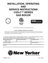
HOW TO INSTALL
Remove gauge glass assembly and nipples
replacing nipples with two 6" brass nipples
provided ➀. Install 1/2" x 1/2" x 3/8" tee ➁
on top nipple.
Install 1/2" x 2" brass nipple ➃and 1/2" x
1/2" x 1/2" tee ➂to 1/2" threaded hole in
casting ➄.
NOTE: Casting is designed for either left or
right mounting on gauge glass. Be sure to
plug hole on opposite side.
Thread tee attached to casting into bottom 6"
nipple. Tighten until casting is vertical.
Install compression fittings ➆into casting
and top tee. Size copper tubing ➅and tight-
en between the two compression fittings.
Attach control to probes using No. 8-32 self
tapping screws provided. Install nipple and
blow down valve (with discharge line) in bot-
tom 3/4" tapped hole.
Reattach gauge glass cocks and gauge glass
into end of 1/2" tees. Pressure-trol can be
threaded into 1/8" threaded hole on top of
casting. If pressure-trol is not used, plug
1/8" hole on top of casting.
Attach blue probe lead wire to upper probe
and white probe lead wire to bottom probe
with wing nuts and lock washers provided.
MODEL 711 COMES WITH:
➀ (2) 6" x 1/2" brass nipples
➁ (1) 1/2" x 1/2" x 3/8" tee
➂ (1) 1/2" x 1/2" x 1/2" tee
➃ (1) 2" x 1/2" brass nipple
➄ (1) 711C manifold casting
➅ (1) 3/8" copper tube
➆ (2) 3/8" compression fittings
➇ (1) 3/4" nipple
➈ (1) Blow down valve
1
234
567
2
NOTE: Discharge line
not included.

WIRING METHOD A: Same 120V Power Source for Control and Burner Circuit
WIRING METHOD B: For use with Gas Boilers or Separate Power Source for Control and Burner Circuit
BURNER
POWER
SOURCE
120V
AC
60HZ
NEUTRAL
HOT
DISCONNECT
SWITCH
BURNER
POWER
SOURCE
120V
AC
60HZ
BURNER
POWER
SOURCE
120V
AC
60HZ
NEUTRAL
HOT
BURNER
+0
LIMIT
CONTROLS
BURNER
POWER
SOURCE
120V
AC
60HZ
BURNER
+0
FEEDER VALVE
CONTROL
POWER
SOURCE
120V
AC
60HZ
NEUTRAL
HOT
DISCONNECT
SWITCH
CONTROL
POWER
SOURCE
120VAC
60HZ
HOT
BURNER
CIRCUIT
DISCONNECT
SWITCH
CONTROL
POWER
SOURCE
120V
AC
60HZ
+0
LIMIT
CONTROLS
BURNER
CIRCUIT
CONTROL
POWER
SOURCE
120V
120V
AC
60HZ
+0
LIMIT
CONTROLS
BURNER
CIRCUIT
FEEDER VALVE
A1 Connect input voltage (120 VAC,
60HZ) to terminals 2 and 1. 120
VAC, 60HZ must be supplied to terminals 2
and 1 for internal operation of the control.
Install a jumper between terminal A2
1 and terminal P1. Power from
terminal P1 is supplied to terminal P2 when
water reaches the upper probe. Power to ter-
minal P2 is removed when water falls below
the bottom probe.
A3 Connect terminal 2 to burner circuit
neutral. Connect terminal P2
to burner circuit in series with other limit
controls. Consult boiler manufacturer’s
instructions for proper terminal connections.
NOTE: Control is wired in series with and
before other limits.
Feeder Connection: Connect feeder A4
common to terminal 2. Connect
feeder hot to terminal A. Whenever water
falls below the lower probe, power is sup-
plied to the feeder terminal A. When water
reaches the upper probe, power to the feeder
is removed.
B1 Connect input voltage (120 VAC,
60HZ) to terminals 2 and 1. 120
VAC, 60HZ must be supplied to terminals 2
and 1 for internal operation of the control.
Connect hot lead from burner B2
control circuit to terminal P1.
This terminal supplies power to terminal P2
in normal operating conditions when water
is at the probe. Connect neutral to burner
circuit.
NOTE: Consult boiler manufacturer’s instruc-
tions for proper terminal connections.
B3 Connect terminal P2 to burner cir-
cuit in series with other limit
controls. Consult boiler manufacturer’s
instructions for proper terminal connections.
NOTE: Control is wired in series with and
before other limits.
Feeder Connection: Connect feeder B4
common to terminal 2. Connect
feeder hot to terminal A. Whenever water
falls below the lower probe, power is sup-
plied to the feeder terminal A. When water
reaches the upper probe, power to the feeder
is removed.
NOTE: All schematic diagrams show all systems in
the off position. No power applied.
A1
A3 A4
B1 B2
B3 B4
A2
3

INSTALLATION & OPERATION OF FEEDER: For WF Models ONLY
A feed valve is supplied standard with con-
trol model 711WF. It is recommended that a
shut-off valve and union be installed on
either side of the water feed valve and a by-
pass valve and piping be installed to permit
removal of the water feed valve should serv-
ice be required. During normal operation,
by-pass valve should be closed and isolation
valves should remain open.
PRINCIPLE OF OPERATION
Hydrolevel controls are electronically operat-
ed. Water is used as an electrical conductor
to complete a circuit from the probe to the
control unit. The control unit provides
switching contacts to operate the burner cir-
cuit and optional water feeder.
The 711 Series low water cut-off is designed
to maintain a safe operating water level in
the boiler. When water is in contact with the
upper probe, the control enables the burner
to fire (switch contacts P1 – P2 are closed).
When the water level falls below the lower
probe, the control will de-energize the burn-
er circuit. The control will not re-energize the
burner until the water level is restored to the
upper probe level.
The 711WF includes a feed valve designed to
automatically restore the water level in the
event of a low water condition. When water
falls below the lower probe, the 711 will
energize the feed valve (switch contact 1 –
A make). When the boil er water level is
restored to the upper probe, the 711 will de-
energize the feed valve and restore burner
operation. The 711CF does not include a
feed valve, but does provide contacts for
operation of a steam boiler water feeder.
NOTE: 711CF is only compatiable with
a 120V Feeder
See page 6 for information on the VXT
Water Feeder.
4
The following maintenance must be performed by a qualified service technician:
Annually
• Remove and clean the strainer located on the valve body. IMPORTANT: If the strainer shows signs of mineral deposits collecting on the
screen, install a Hydrolevel Feed Valve Service Kit (Part No. 45-715).
Every 3 Years
Install Hydrolevel Feed Valve Service Kit (Part No. 45-345). Note: If hardened calcium deposits have formed on the brass surface inside the
valve, replace the valve (Part no. 45-343).
12 Years
Replace the Feed Valve Assembly after 12 years of service.
WARNING Water Damage Potential: Failure to maintain the feed valve can result in excess mineral deposits
collecting in the valve. If left unchecked, these deposits can impede valve operation with the potential
for overfilling the heating system and allowing water to escape radiators into the living space.
Feed Valve Maintenance (WF Models Only)

SERVICE / MAINTENANCE
The 711 Series Control requires regular
maintenance to ensure continued, safe oper-
ation. During normal boiler function, sedi-
ment may accumulate in the low water cut-
off's probe housing. If left unchecked, this
sediment can build up, trap water in the
probe housing, and prevent the control from
detecting a low water condition in the boiler.
A regular blow down of the control is
required for proper operation.
To flush the sediment from the chamber, the
control must be blown down throughout the
heating season in accordance with the fol-
lowing schedule:
• Daily for first week following control
installation
• Prior to heating season startup in the fall
• Once per week during the heating season
Instructions: Confirm water is visible in the
gauge glass. If not visible, shut the burner
off, allow the boiler to fully cool, then add
water until visible in the gauge glass. Once
water is visible, bring your boiler back up to
temperature. With the boiler running, place a
heat resistant pail directly beneath the con-
trol casting blow down valve. Open the valve
and allow the sediment and water to drain
into the pail. Continue to drain the water
until it runs clean (One to two gallons is gen-
erally sufficient). Close the valve when com-
pleted. Replenish the water in the boiler if
needed.
OPERATING INSTRUCTIONS
TROUBLESHOOTING
1If the burner does not shut down upon
water falling below the lower probe:
Remove power to the burner and check
installation. Check wiring and make sure
that burner is connected to the fourth ter-
minal from left on terminal (P2). If wiring
is correct, check to make sure the probes
are not falsely grounded. Voltage between
the probes and chassis ground should be
120-140 VAC with water beneath both
probes. A lower reading may indicate a
shorted probe. Remove probes and check
for contamination.
2If the burner will not fire with water at the
top probe: With a voltmeter and power
applied at terminals G and H: Check the
voltage between the upper probe and
chassis ground. Reading should be 0-10
VAC with water at the upper probe. A
higher reading may be the result of poorly
conductive water or probe contamination.
Remove probes and check for contamina-
tion. If the burner will still not fire after
cleaning probes, contact factory for assis-
tance.
5
DIMENSIONS
NOTE: Hydrolevel recommends that the boil-
er manufacturer’s procedures for skimming
the boiler be performed prior to placing the
control into operation.
1After installation, raise the boiler water
level until water is in contact with the
upper probe. Turn on power and set the
thermostat to call for heat. The burner
should fire immediately.
2Using the boiler drain, slowly lower the
water level to a point below the lower
probe. The burner should shut down
immediately upon a low water condition.
NOTE: The water should not be lowered
beyond a visible point on the gauge glass.
IMPORTANT: If the burner does not shut
down in a low water condition, turn off
power immediately and refer to trou-
bleshooting instructions below.
REGULAR MAINTENANCE
REQUIRED. Failure to
properly maintain the control can lead to
severe damage to the boiler, other property,
personal injury, or death.
To prevent serious person-
al injury from steam and
hot water, make sure there is a discharge line
from the blowdown valve to a proper place of
disposal. Failure to follow this caution could
result in personal injury.

SPECIFICATIONS
MAXIMUM PRESSURE: 15 PSI
INPUT VOLTAGE: 120 VAC, 60 HZ
SWITCH RATINGS: 5.8 FLA, 34.8 LRA
SWITCH CONTACTS: SPDT
ALARM CIRCUIT: 125 VA @ 120 VAC
Pilot Duty
LIMITED MANUFACTURER’S WARRANTY
We warrant products manufactured by Hydrolevel Company to be free
from defects in material and workmanship for a period of two years from
the date of manufacture or one year from the date of installation,
whichever occurs first. In the event of any claim under this warranty or
otherwise with respect to our products which is made within such peri-
od, we will, at our option, repair or replace such products or refund the
purchase price paid to us by you for such products. In no event shall
Hydrolevel Company be liable for any other loss or damage, whether
direct, indirect, incidental or consequential. This warranty is your EXCLU-
SIVE remedy and shall be IN PLACE OF any other warranty or guarantee,
express or implied, including, without limitation, any warranty of MER-
CHANTABILITY or fitness for a particular purpose. This warranty may not
be assigned or transferred and any unauthorized transfer or assignment
thereof shall be void and of no force or effect.
OPTIONS
The VXT water feeder (available separately)
can be used with Hydrolevel or other low
water cut-offs to automatically replenish
boiler water in the event of a low water con-
dition. The VXT offers programmable feed
amount and feed delay settings. These can
easily be set to ensure the proper feed
amount and to provide adequate time for
condensate to return to the boiler before
starting a feed cycle. The VXT’s digital feed
counter tracks the amount of water added to
the boiler exposing system leaks, which can
significantly shorten the life of a cast iron
boiler. Additional features including a manual
feed button underfeed and flood protection,
make the VXT an ideal choice for safety and
convenience.
126 Bailey Road, North Haven, CT 06473 • Phone (203) 776-0473 • FAX (203) 764-1711 • www.hydrolevel.com
WARNING Frozen pipes/water damage. Central heating systems are prone to shut down as a result of power or fuel outages,
safety related fault conditions or equipment failure. Installation of freeze protection monitoring or other precautions
is recommended for unattended dwellings in climates subject to sustained below-freezing temperatures.
041822
6
/