OMB EM 250 COMPACT DIG Technical Manual
- Category
- Audio amplifiers
- Type
- Technical Manual

TECHNICAL MANUAL
v1.1 February 2006
SISTEMAS ELECTRONICOS S.A.
2
25
50
0W
WS
SO
OL
LI
ID
DS
ST
TA
AT
TE
E
F
FM
MT
TR
RA
AN
NS
SM
MI
IT
TT
TE
ER
R
E
EM
M2
25
50
0
C
CO
OM
MP
PA
AC
CT
TD
DI
IG
G
OMB EUROPE:
Factory: Camino de los Albares,14 -Ph. 976.50.35.80, Fax: 976.50.38.55 – 50410 CUARTE DE HUERVA (Zaragoza) ESPAÑA
Sales Dpt.: Avda. San Antonio,41– Ph. 976.50.46.96, Fax: 976.46.31.70 – 50410 CUARTE DE HUERVA (Zaragoza) ESPAÑA
E-mail: [email protected]
Web: www.omb.es
OMB USA:
3100 NW 72nd. Avenue Unit 112 – MIAMI, Florida 33122 – Ph.: 305 477-0973, 305 477-0974, Fax: 305 477-0611
E-mail: [email protected]
Web: www.omb.com

OMB ESPAÑA
Av. San Antonio, 41
50410 Cuarte de Huerva
ZARAGOZA (ESPAÑA)
Website: http://www.omb.com
e-mail: [email protected]
Tlf: + 34 976 50 46 96
Fax: + 34 976 46 31 70
SISTEMAS ELECTRÓNICO
S
Nº Es01-022 Nº Es01-E021

LIMITED WARRANTY
About Installation_____________________________________________________________
1. - Mains Voltage must be kept between ±10% about its nominal value, unless otherwise
specified. If were variations exceeding this tolerance, it will be indispensable to install a voltage
stabilizer system within station. If transient overvoltages, due to electric motors, or other devices
of this sort connected to the distribution line, were present, or if the distribution line is exposed
to atmospheric electrical discharges, it must be indispensable the installation of isolation
transformers and gaseous dischargers before connecting any equipment within station.
2. - All equipments must be connected to station ground system in order to avoid damage
both to equipments and maintenance personnel too. It is necessary to connect a differential
automatic switch (lifesaver) at station.
3. - Some equipments does not include interlock protection for open doors, covers or
connectors. In that case, these equipments must be kept in key –locked places, with access
only to conveniently qualified personnel that is previously noticed about not to open doors,
covers or connectors without disconnecting station mains switch before performing this job.
4. - Transmitter equipments NEVER will be operated with output powers over its nominal values,
or with signals or input informations others than those specified in its individual characteristics.
5. - Ambient temperature inside equipments' room, will accomplish technical specifications of
equipments installed at station lodge. In absence of such specifications, maximum allowable
temperatures will be from -5 to + 45ºC for Television equipments, and from 0 to + 40ºC for
Sound Broadcast equipments.
6. - In case of operation at abnormally high or extremely high temperatures (over 30 to 40 º
C), it is obligatory to install a forced cooling system that will keep temperature below its upper
limit. In case of operation at abnormally or extremely low temperatures, it will be obligatory to
install a thermostatic controlled heating system for equipment's room.
7. - Both equipment's surroundings and room must be free of dust and dirt. Ambient relative
humidity will be kept below equipment's extreme specifications. In case of absence of this
specification, allowable maximum will be 90 % of relative humidity, non-condensing. Average
relative humidity will be kept under 70%, non-condensing.
8. - Every transmission equipment that can radiate some quantity of RF power, must be
connected to a load or antenna system, suited to its individual specifications , before being
energized.
9. - Maximum allowable VSWR in antenna systems both for Television or FM Radio Broadcast
operation of a given transmitter, will be 1.25:1, unless otherwise specified.
10.- For those transmitter equipments having power valve amplifiers, and that doesn't has an
automatic shutoff cycle, and must be manually turned off, as a first step high voltage, or
anode voltage, will be disconnected, keeping forced cooling system working during at least 5
minutes after high voltage disconnection, and only after this time, cooling system & filament
voltage can be shutted off. O.M.B. Sistemas Electrónicos, S.A., is not responsible of damages
to those power valves caused by sudden AC mains failures at station where our equipments
are installed.
11.- Periodically, monthly as a maximum, technical personnel must visit station in order to
perform a general equipment maintenance, unless otherwise specified. This maintenance will
include output power check, VSWR of antenna systems, forced cooling or heating systems

checks, both for equipments and station itself, including air filters cleaning, measuring of
transmission frequency with eventual correction if necessary, and will perform a general check
of fundamental parameters of equipments. In the event of any important change in some
operation parameter, that will require replacement or readjustment of any unit, Customer
MUST CONTACT FIRST WITH O.M.B. SISTEMAS ELECTRONICOS, S.A. BEFORE ANY ATTEMPT TO
READJUST OR REPLACE ANY COMPONENT OR UNIT INSIDE EQUIPMENTS, IN ORDER TO KEEP
VALID THIS WARRANTY.
12.- For equipments who are located in fixed racks or cabinets, those equipments must be
effectively connected, according to International Installations Standards, to station ground
system, whose total impedance measured to ground can't be higher than 5 ohms.
Equipments must be connected to ground system so that they can be kept out of main
discharge path between tower and ground.
About Transportation___________________________________________________________
1. - O.M.B. Sistemas Electrónicos, S.A. is not responsible of damages and/or detriments derived
from mishandling, steal, robbery, theft or vandalism during the act of transportation of
equipments to final or intermediate destination.
About Storage________________________________________________________________
1. - O.M.B. Sistemas Electrónicos, S.A. is not responsible of damages and/or detriments derived
from unappropiate storage of equipments, within inadequate warehouses or outdoors, once
equipments are delivered to transportist agency.
About Projects________________________________________________________________
1.- O.M.B. Sistemas Electronicos, S.A. is not responsible of inadequate use of equipments
made or registered by our Company, accomplishing propagation projects that are not
performed by our Specialists.
About Systems________________________________________________________________
1.- O.M.B. Sistemas Electrónicos, S.A. is not responsible for performance of those equipments
or systems that are not made, certified or registered by our Company.
About Operation______________________________________________________________
1.- O.M.B. Sistemas Electrónicos, S.A. is not responsible of damages and/or detriments derived
from inadequate or negligent operation of equipments made, certified or registered by our
Company, once those equipments are operated by personnel hired and/or employed by
Customer.
General______________________________________________________________________
This Warranty covers and protects, during a period of 18 months after start of operations, all
equipments made , certified or registered by O.M.B. Sistemas Electrónicos, S.A., including its
components and units, against failures in workmanship that may occur during operation of
those equipments, with the exception of power valves or semiconductor devices that are
covered by its particular Factory's Guarantee. In this case, O.M.B. Sistemas Electrónicos, S.A.
only can act as intermediary for negotiation with such Factory, about accomplishment of
individual Guarantees.

For Validity of this Warranty, it is indispensable that all Paragraphs be respected by the
Customer. Otherwise, this Warranty will be automatically voided. This Warranty is self-activated
with the reception by OMB Sistemas Electrónicos, S.A. of the "Guarantee Activation Manual"
returned to OMB by Customer. If such Document is not received, this Warranty will be
voided.
All repairings or adjustments covered by this Warranty are free of workmanship & materials
costs and expenses, but postage and transportation expenses of equipments and O.M.B.
technical personnel & specialists, if required, will be carried out by the Customer.
O.M.B. Sistemas Electrónicos, S.A.

FM Transmitter
Sistemas Electrónicos S.A EM 250 COMPACT DIG
Technical Manual - v1.1 - February 2006 1
LIST OF CONTENTS
SECTION 0. GENERAL RECOMMENDATIONS 2
Gives information on safety procedures and good practices to use the equipment.
SECTION 1. GENERAL DESCRIPTION 6
Introduction to the manual, technical specifications and description of the equipment’s features.
SECTION 2. DESCRIPTION OF INTERNAL MODULES 14
Contains a deep description of the system operation, including lists of components, schematics and
layouts.
SECTION 3. INSTALLATION AND MAINTENANCE 53
Contains basic instructions for unpacking and installing the equipment and recommended maintenance
operations for a good system operation.
SECTION 4. SETTINGS 63
Instructions to configure the equipment by using the software installed.


FM Transmitter
Sistemas Electrónicos S.A EM 250 COMPACT DIG
Technical Manual - v1.1 - February 2006 3
GENERAL SAFETY RECOMMENDATIONS
When connecting the equipment to the Mains power, please follow these important
recommendations:
This product is intended to operate from a power source that will not apply more than 10% of
the voltage specified on the rear panel between the supply conductors or between either supply
conductor and ground. A protective-ground connection by means of the grounding conductor in
the power cord is essential for a safe operation.
This equipment is also grounded through the grounding conductor of the power cord. To avoid
electrical shock, plug the power cord into a properly wired socket before connecting to the
product input or output terminals.
Upon loss of the protective-ground connection, all accessible conductive parts (including parts
that may appear to be insulated) can render an electric shock. Equipment must be connected
to station's ground system before any attempt to connect it to Mains electrical supply.
To avoid fire hazard, use only fuses of the type, voltage rating, and current rating specified in this
manual. For fuse replacement, always refer to User’s Manual.
To avoid explosion, do not operate this equipment in an explosive atmosphere.
To avoid personal injury, do not remove the product covers or panels. Do not operate the
product without the covers and panels properly installed.
GOOD PRACTICES
During the maintenance of the equipment covered in this Manual, please keep in mind the following
standard good practices:
When connecting any instrument (wattmeter, spectrum analyzer, etc.) to a high frequency output,
use the appropriate attenuator or dummy load to protect the final amplifiers and the instrument input.
When inserting or removing printed circuit boards (PCBs), cable connectors, or fuses, always turn off
power from the affected part of the equipment. After power is removed, allow sufficient time for the
capacitors to bleed down before reinserting PCBs. Always use discharge stick when available.
When troubleshooting, remember that FETs and other metal-oxide-semiconductor (MOS) devices
may appear defective because of leakage between traces or component leads on the printed circuit
board. Clean the printed circuit board and recheck the MOS device before assuming it is defective.
When replacing MOS devices, follow standard practices to avoid damage caused by static charges
and soldering.
When removing components from PCBs (particularly ICs), use care to avoid damaging PCB traces.

FM Transmitter
Sistemas Electrónicos S.A EM 250 COMPACT DIG
Technical Manual - v1.1 - February 2006 4
FIRST AID IN CASE OF ELECTRICAL SHOCK
If someone seems unable to free himself while receiving an electric shock, turn power off before
rendering aid. A muscular spasm or unconsciousness can make a victim unable to free himself from
the electrical power.
If power cannot be turned off immediately, very carefully loop a length of dry non-conducting
material (such as a rope, insulating material, or clothing) around the victim and pull him free of the
power. Carefully avoid touching him or his clothing until free of power.
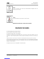
EMERGENCY RESUSCITATION TECHNIQUE
Step 1
Check the victim for unresponsiveness. If there is no response, immediately call
for medical assistance, and then return to the person.
Step 2
Position the person flat on their back. Kneel by their side and place one hand on
the forehead and the other under the chin. Tilt the head back and lift the chin
until teeth almost touch. Look and listen for breathing.
Step 3
If not breathing normally, pinch the nose and cover the mouth with yours. Give
two full breaths. The person's chest will rise if you are giving enough air.
Step 4
Put the fingertips of your hand on the Adam's apple, slide them into the groove
next to the windpipe. Feel for a pulse. If you can not feel a pulse or are unsure,
move on to the next step.
DO NOT TOUCH VICTIM OR HIS CLOTHING
BEFORE POWER IS DISCONNECTED OR YOU
CAN ALSO BECOME A SHOCK VICTIM

FM Transmitter
Sistemas Electrónicos S.A EM 250 COMPACT DIG
Technical Manual - v1.1 - February 2006 5
Step 5
Position your hands in the center of the chest between the nipples. Place one
hand on top of the other.
Step 6
Push down firmly two inches. Push on chest 15 times.
CONTINUE WITH 2 BREATHS AND 15 PUMPS UNTIL HELP ARRIVES.
TREATMENT FOR BURNS
Continue treating victim for electrical shock.
Check for points of entry and exit of current.
Cover burned surface with a clean dressing.
Remove all clothing from the injured area, but cut around any clothing that adheres to the skin
and leave it in place. Keep the patient covered, except the injured part, since there is a tendency to
chill.
Splint all fractures. (Violent muscle contractions caused by the electricity may result in fractures.)
Never allow burned surfaces to be in contact with each other, such as: areas between the fingers or
toes, the ears and the side of the head, the undersurface of the arm and the chest wall, the folds of
the groin, and similar places.
Transport the victim as soon as possible to a medical facility.

FM Transmitter
Sistemas Electrónicos S.A EM 250 COMPACT DIG
Technical Manual - v1.1 - February 2006 6
CONTE
N
T
S :
1.1 Introduction . . . . . . . . . . . . . . . . . . 7
1.2 Description . . . . . . . . . . . . . . . . . . . 7
1.3 Front panel . . . . . . . . . . . . . . . . . . . 9
1.4 Rear panel . . . . . . . . . . . . . . . . . . . 11
1.5 Inner layout . . . . . . . . . . . . . . . . . . . 12
1.6 Technical specifications . . . . . . . . . . . . 13
S
Se
ec
ct
ti
io
on
n1
1
G
GE
EN
NE
ER
RA
AL
L
D
DE
ES
SC
CR
RI
IP
PT
TI
IO
ON
N

FM Transmitter
Sistemas Electrónicos S.A EM 250 COMPACT DIG
Technical Manual - v1.1 - February 2006 7
1.1 Introduction.
The OMB EM-250 COMPACT DIG series transmitters are the result of experience gained by OMB during
years of producing FM broadcast equipment, transmitters, stl and stereo encoders. These transmitters
were specifically designed to comply with the latest international standards and the requirements of
advanced broadcasters,meeting tighter specifications than usually required,at an affordable cost.
Great care went into producing a Hi-Fi-quality modulated signal,with low residual noise and
distortion.The RF signal is also free from spurious and harmonic components to a higher degree than
required by CCIR, European, USA and most other national standards.To obtain this outstanding
performance, OMB strongly recommend to rely on qualified personnel to install and verify the
equipment which makes up the radio station, i.e.the transmitter, the possible stl and power amplifier,
the corresponding antennas,cables and connectors.This will assure to achieve the best performance
and stability in time. To this aim,OMB especially recommend that their equipment should not be
tampered with by unskilled personnel and its after-sale service is available to customers for any
technical problem.Before proceeding to installation, please carefully read at least the general
installation part of this manual, to gain confidence with the equipment.
The EM-250 COMPACT DIG transmitters are very stable and changes to the internal pre-setting other
than frequency and few other options are not usually required but, if they are, once again they must
be done by skilled personnel, fitted with proper instrumentation and service documentation.
Improperly tampering with the settings may harm the apparatus or jeopardize the guaranteed
performance.
THIS EQUIPMENT COMPLIES WITH ALL RELEVANT EMI /EMC AND SAFETY REQUIREMENTS, ETSI EN300384,
ETS300447 AND EN60215 STANDARDS.
NO INTERNAL ADJUSTMENT OR PRESETTING IS REQUIRED DURING NORMAL OPERATION.EQUIPMENT SHALL
BE PROPERLY GROUNDED AND BE OPERATED WITH ALL THE COVERS CLOSED TO PREVENT ELECTRICAL
HAZARDS AND COMPLY WITH EMC STANDARDS.
OMB hence recommends for these equipments not to be handled by unskilled personnel,together
with antenna system, transmission lines and the remaining components, both at Transmitters and
related equipments and station's antennas system.
A good installation,made by skilled and trained personnel will avoid many future troubles during
station's exploitation process. All the operations described in the Certification of Limited Warranty must
be accomplished to have the right of make any claim concerning this Warranty,having free
equipment service by OMB's technical personnel during this first exploitaition phase of Equipment.
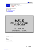
1.2 Description.
The EM-250 COMPACT DIG is a 250W rated, direct-synthesis, FM-modulated transmitter. Being digitally
controlled, it is extensively put on the air on field by front panel or remotely in additional aspects:
frequency, power, channel sensitivity, preemphasis, functioning mode (mono, stereo, external mpx),
clock and date and many other parameters without adjusting or substituting any part. A powerful 3-
level password management permits a very high degree of security and privacy as may be required
in different situations. Equipment requires little o no maintenance and its simple modular layout
facilitates stage testing and servicing.

FM Transmitter
Sistemas Electrónicos S.A EM 250 COMPACT DIG
Technical Manual - v1.1 - February 2006 8
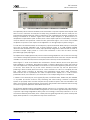
Fig. 1-1: THE EM-250 COMPACT DIG DIGITALLY-CONTROLLED F.M. TRANSMITTER
As imposed by various national standards, these transmitters incorporate sophisticated low-pass audio
filters on mono and stereo channels,and a sharp acting modulation limiter, which is usually set at a
peak deviation slightly higher than 75kHz. Its intervention may nevertheless be avoided, if required, pre-
setting its threshold at a deviation higher than 150kHz. Output frequency is phase-locked to a
temperature-compensated crystal oscillator,which ensures superior precision and stability. A very low
noise,low distortion VCO produces a harmonic-free, spurious-free signal. A lock control circuit inhibits
the presence of power on the output until the apparatus is on the right frequency,when turning on.
To lower the noise threshold further, the low-frequency inputs are fitted with balanced input circuitry.The
input level is precisely adjustable over a broad range,by means of a 0.5dB stepwise variable
attenuators.The transmitter has an auxiliary input,specifically designed for RDS and SCA encoders. A
modulation sample output permits to control other transmitters or STL's with the same internally
processed high-quality mpx signal.
The alphanumeric display permits easy and accurate metering,adjustment and continuous monitoring
of modulation levels,power,operation and internal parameters.All these information may be externally
available on the same RS-232 I/O bus that may be used to remotely control the transmitter.
Above Figure 1-1 shows us the external view of Modulator / Exciter's cabinet, whose control panel has
been simplified to a maximum, being Microcontroller in charge of practically to select and make all
tests and adjustments of all parameters that are relevant to the normal Equipment's performance. Due
to this fact, Front Panel has only a few control elements, since with only the four push buttons
pertaining to Microcontroller (like those used to control movement of cursor in a Computer) and two
keys, these virtually controlling all processes and parameters having place within Equipment.
Microcontroller uses a Liquid-Crystal dot matrix as Alphanumeric Display unit in order to watch
parameter's values, as it's asked for it, as can be seen in the corresponding section in this Manual.
In addition to the serial I/O port, some signals (RF power, ON THE AIR status, Disable line) are available
on a parallel I/O remote socket for easy interfacing with others analog controllers or supervisory
systems. A top-quality stereo encoder may be factory installed as option and even retrofitted in the
field in a second time, requiring minimum technical skill. The powerful internal software and monitoring
functions recognizes its presence and enables its functions.
The RF power amplifier employs a broadband design and has a lot of of reserve: the output power is
feedback-controlled for increased stability still higher than nominal level. High reflected power is limited
to prevent output stage degradation;direct power is accordingly continuously reduced so as not to
exceed the reflected power safety level. A sturdy telecom-grade high efficiency switch-mode power
supply allows operation in a very wide and noisy mains environment.

FM Transmitter
Sistemas Electrónicos S.A EM 250 COMPACT DIG
Technical Manual - v1.1 - February 2006 9
1.3 Front panel.
The EM-250 COMPACT DIG Front Panel is very clean and easy to control.The wide alphanumeric
display and the control keyboard allows a simple self-explanatory menu-driven navigation through the
various options. A great care was taken in the design of the software to allow natural feeling with the
controls to allow operation and programming in every respect of the Equipment without needing to
extensively read this manual.
The password management hides some functions and prevents tampering with the most critical
options and data to unauthorized people.
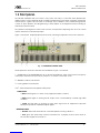
Figure 1-2 shows the simple Equipment's Front Panel, indicating all supervision and control elements:
Fig. 1-2: TRANSMITTER CONTROL PANEL.
These supervision andcontrol elements are numbered in Figure 1-2 as follows:
1 - ON/STBY switch. This ON/STANDBY key do not power off equipment, which is still locked on frequency
and ready to transmit as soon the key is pushed or a remote command is sent.
2 - STANDBY condition indicator LED.
3 - Cooling system's air intake slots.
4 & 7 - Alarm LEDs panel and operation LEDs panel:
ALARM PANEL:
•Alarm red LED lights on in event of any equipment's alarm condition.
•VSWR red LED lights on showing that RF output circuit is overloaded by a severe high VSWR
condition.
•Limiter red LED lights on showing too high audio signal level at equipment's input,and
subsequent operation of baseband peak clipper.
OPERATION PANEL:
•Remote amber LED shows remote-controlled operation is being carried on.
•Lock green LED shows when Channel Oscillator's PLL is properly locked, some tenths of
second after equipment is turned on.

FM Transmitter
Sistemas Electrónicos S.A EM 250 COMPACT DIG
Technical Manual - v1.1 - February 2006 10
•On the air green LED works together with STANDBY (2) yellow LED. It lights on when equipment
is in normal operating condition, whereas STANDBY (2) LED is turned off, and vice versa.
5 - Twin-row Alphanumeric dot-matrix LCD display, working directly with Microcontroller unit.
6 - DISPLAY CONTRAST potentiometer, to adjust LCD screen backlighting to a comfortable
contrast level in order to get easy readings.
8 - Programming and parameter selection keyboard:
White keyboard to scroll and navigate through the different menus and options.
OK key (blue). Enter key to confirm some order or command.
CANCEL key (orange). Escape key to cancel menu or command.

FM Transmitter
Sistemas Electrónicos S.A EM 250 COMPACT DIG
Technical Manual - v1.1 - February 2006 11
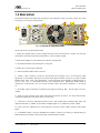
1.4 Rear panel.
All transmitter inputs and outputs are allocated on the rear panel. Figure 1-3 below shows this Panel
indicating all connectors and elements.
Fig. 1-3: REAR VIEW OF TRANSMITTER CABINET.
These elements are numbered as follows:
1 -Mains IEC ON/OFF switch, mains voltage selector,socket and fuses block. Please note that the
transmitter is usually factory pre-set for 220-240VAC nominal Mains voltage.
2 -Main Power Supply's hot air exhaust from internal cooling blower.
3 - RF Power Module's hot air exhaust from cooling fan.
4 -Output RF connector.Type "N"female.
5 - Remote operation DB-9 male connector.
6 - RS-232 serial interface connector. This RS-232 port manages only Tx, Rx and Return data
signals,with no handshake. Being the two former wired signals inverted to the port, it needs a simple
straight wired serial cable with appropriate connectors:usually a female DB-9 or DB-25 female to
the PC port and a male DB9 connector at the transmitter end. Appropriate OMB software is
required for communication. Do not connect the serial cable with neither transmitter or PC turned
on.
7 - RF sample output for frequency measuring or RF signal monitoring, BNC female type connector.
-50dBc.
8 - Right and left channels audio input XLR balanced female connector. For using internal stereo
coder. (See equipment's rear panel for pin connections).
9 - MPX input connector. Type BNC female.For use in pre-coded stereo multiplex signal input. Flat
response from10Hz to 100KHz to feed stereo multiplex signal. Hi - Z unbalanced input (10K:).
10.- AUX connector. Unbalanced Hi-Z BNC female connector,to feed a RDS or SCA encoder output
signal.
11.-LF MONITOR output connector. Baseband modulation output for monitoring, re-broadcasting or
RDS external synchronization. BNC female type, unbalanced Hi-Z (10K:).

FM Transmitter
Sistemas Electrónicos S.A EM 250 COMPACT DIG
Technical Manual - v1.1 - February 2006 12
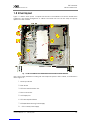
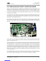
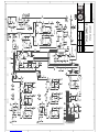
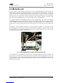
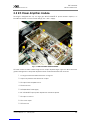
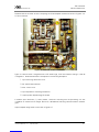
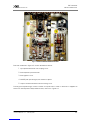
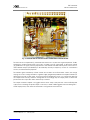
1.5 Inner layout.
Figure 1-4 below shows space occupied and allocation of the different units and PC boards within
equipment, and internal arrangement of cabinet. All boards and units can be easily and quickly
replaced in case of failure:
Fig. 1-4: EM-250 COMPACT DIG TRANSMITTER.UPPER VIEW WITH COVER REMOVED.
Units can be easily identified according with their respective position within cabinet, as numbered in
above Figure 1-4 :
1 - Audio Input board.
2 - Main board.
3 - RF Exciter and Modulation Unit.
4 - Microcontroller Unit.
5 - LCD Display Unit.
6 - RF Power Amplifier Module.
7 - SP-500/48 Main Switching Power Supply.
8 - +15VDC Auxiliary Power Supply.
Space
reserved for
optional
Stereo
encoder

FM Transmitter
Sistemas Electrónicos S.A EM 250 COMPACT DIG
Technical Manual - v1.1 - February 2006 13
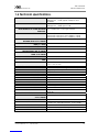
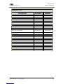
1.6 Technical specifications.
SIGNAL TO NOISE RATIO Monaural >78dB, typical 86dB (from 30 to 20,000Hz)
Stereophonic >72dB, typical 77dB (from 30 to
20,000Hz)
CCIR WEIGHTED S/N Monaural >75dB, typical 81dB.
Stereophonic >68dB, typical 77dB.
HARMONIC DISTORTION
NOTE:LIMITER SET TO 150KHZ DEVIATION
THRESHOLD.
For ± 75 KHz dev <0.05%, typical 0.02%
For ±150 KHz dev <0.2%, typical 0.05%
STEREO CROSSTALK w/External Encoder <-50dB.
w/Internal Encoder (from 100 to 5000Hz) <-60dB
w/Internal Encoder (from 30 to 15000Hz) <-50dB
PROGRAM AUDIO CHANNEL FREQUENCY
RESPONSE FROM 30 TO 15000HZ
± 0.1dB
ATTENUATION AT AUDIO FILTER REJECTION
BAND (F =19KHZ)
>50dB
DEVIATION LIMITER THRESHOLD Adjustable between 0 and +7dBm
STEREO MULTIPLEX INPUT FREQUENCY
RESPONSE.FROM 10HZ TO 100KHZ
±0.1 dB
AUXILIARY INPUT FREQUENCY RESPONSE
.FROM 10 TO 100KHZ
±0.2 dB
MAINS SUPPLY REQUIREMENTS 90 ~ 260VAC , 50/60 Hz
POWER CONSUMPTION AT 250W RF OUTPUT
LEVEL
600 VA / 480W
OPERATING TEMPERATURES RANGE 0 to +35 ºC recomm.
-10 to +45 º C max
MOUNTING DIMENSIONS (W/O HANDLES) Width:19" Height: 3RU in standard 19" Rack.
DIMENSIONS 483mm width x 125mm height x 334mm depth
MODULATION Frequency, ± 75KHz. peak dev
MODULATION CLASS F3E, F8E
OSCILLATOR'S SYNTHESIS STEPS 10 /100KHz
FREQUENCY ERROR <± 200Hz
FREQUENCY DRIFT <250Hz, over temperature <100Hz/year
RF OUTPUT POWER Adjustable between 2 and 250WRMS nominal
MAXIMUM ALLOWABLE REFLECTED RF POWER 25W
RF HARMONIC PRODUCTS < -70dBc
RF SPURIOUS PRODUCTS <-80dBc.typical -95dBc
RF OUTPUT IMPEDANCE 50: unbalanced. N Female connector
AUDIO /MULTIPLEX INPUT LEVEL Adjustable between -3.5 and +12.5dBm for ±75KHz
peak dev
AUDIO /MULTIPLEX INPUT IMPEDANCE Select.10K: /600:, bal./unbal
COMMON MODE INPUT REJECTION FROM
20 TO 15000HZ
>50dB, typical >60 dB
AUDIO INPUT CONNECTORS XLR Female balanced
SCA/RDS CHANNEL INPUT LEVEL ±7.5KHz dev: adjustable between -12.5 to +3.5dBm.
±2.0KHz dev: adjustable between -24 and -8dBm.
SCA/RDS CHANNEL INPUT IMPEDANCE 10 K: unbal.BNC Female connector
MODULATION OUTPUT LEVEL From 0 to +10dBm at ±75KHz peak dev
PRE-EMPHASIS TIME CONSTANT Variable: 0 /50 /75 µs ± 2%

FM Transmitter
Sistemas Electrónicos S.A EM 250 COMPACT DIG
Technical Manual - v1.1 - February 2006 14
CONTE
N
T
S :
2.1 Introduction . . . . . . . . . . . . . . . . . . 15
2.2 Audio processor and R.F. control main board . 19
2.3 Stereo encoder (optional) . . . . . . . . . . . 24
2.4 R.F. Exciter unit . . . . . . . . . . . . . . . . . 27
2.5 R.F. Power Amplifier module . . . . . . . . . . 30
2.6 Control unit and display board . . . . . . . . . 41
2.7 Power supply units . . . . . . . . . . . . . . . .47
S
Se
ec
ct
ti
io
on
n2
2
D
DE
ES
SC
CR
RI
IP
PT
TI
IO
ON
NO
OF
F
I
IN
NT
TE
ER
RN
NA
AL
LM
MO
OD
DU
UL
LE
ES
S

FM Transmitter
Sistemas Electrónicos S.A EM 250 COMPACT DIG
Technical Manual - v1.1 - February 2006 15
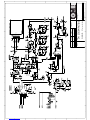
2.1 Introduction.
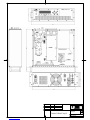
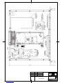
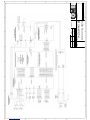
The EM-250 COMPACT DIG transmitter comprises 5 or 6 internal modules, as can be seen in the
general upper view (Figure 1-4) and in the General Wiring Diagram (in next pages). Main units are the
following:
The Main Audio Processor Board.
The Microcontroller Unit and Display Board.
The Stereo Encoder Module (optional).
-The RF Exciter Board.
The RF Power Amplifier Module.
The Switching Regulated Power Supply Units (Main and Auxiliary).
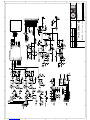
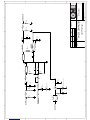
For the detailed description of each module on the following pages, always refer to the corresponding
electrical diagram, included in this section.
Note: the manufacturer reserves the right to change any component value due to production
adjustments.
THIS SECTION IS ONLY AIMED TO GENERAL EXPLANATION,REFERENCE AND SERVICE PURPOSE BY SKILLED
PERSONNEL. AS EXPLAINED IN THE PREVIOUS SECTIONS, INTERNAL ADJUSTMENTS ARE NOT REQUIRED
DURING NORMAL OPERATION. TAMPERING WITH INTERNAL SETTINGS VOIDS THE WARRANTY, MAY HARM THE
APPARATUS AND JEOPARDIZE THE GUARANTEED PERFORMANCE.
DUE TO THE TECHNOLOGY USED,MOST MODULES AND ESPECIALLY THOSE IN SMT ARE NOT INTENDED TO BE
REPAIRED IN CASE OF FAILURE AND MUST BE REPLACED WITH NEW ONES.
Page is loading ...
Page is loading ...
Page is loading ...
Page is loading ...
Page is loading ...
Page is loading ...
Page is loading ...
Page is loading ...
Page is loading ...
Page is loading ...
Page is loading ...
Page is loading ...
Page is loading ...
Page is loading ...
Page is loading ...
Page is loading ...
Page is loading ...
Page is loading ...
Page is loading ...
Page is loading ...
-
 1
1
-
 2
2
-
 3
3
-
 4
4
-
 5
5
-
 6
6
-
 7
7
-
 8
8
-
 9
9
-
 10
10
-
 11
11
-
 12
12
-
 13
13
-
 14
14
-
 15
15
-
 16
16
-
 17
17
-
 18
18
-
 19
19
-
 20
20
-
 21
21
-
 22
22
-
 23
23
-
 24
24
-
 25
25
-
 26
26
-
 27
27
-
 28
28
-
 29
29
-
 30
30
-
 31
31
-
 32
32
-
 33
33
-
 34
34
-
 35
35
-
 36
36
-
 37
37
-
 38
38
-
 39
39
-
 40
40


OMB EM 250 COMPACT DIG Technical Manual
- Category
- Audio amplifiers
- Type
- Technical Manual
Ask a question and I''ll find the answer in the document
Finding information in a document is now easier with AI
Other documents
-
 Sofratec EXB300 User And Maintenance Manual
-
 KatRuud Pira MagicRDS User manual
-
 FMUser FUTV-9422 (500W) User manual
-
EuroTel ETL0480TBD Technical Manual
-
 Sinteck RPU Link User And Technical Manual
-
Sencore SMD 989 User manual
-
AVT 120 Automatic Charger for Lead Batteries User manual
-
 Technosystem SAU125 Operational Manual
-
 R.V.R. Elettronica TEX502LCD User manual
-
 R.V.R. Elettronica TEX702LCD User manual


