Page is loading ...

INSTRUCTION SHEET
COB213
NEMA 12, DIRECT OPERATION
HOIST PENDANT STATION
FEATURES:
• Designed for use with single phase motors up to 1HP, 120VAC (2HP, 220VAC).
• The enclosure is a high-visibility orange color and is constructed of high-impact, high-strength plastic, for operator safety.
• Pendant is designed for single hand operation.
• The unit is dust-tight, drip-tight, and completely insulated to prevent electrical shock.
• Internal and external strain-reliefs plus an internal cable-clamp are provided for added endurance.
• A exible cable entry boot prevents entry of foreign matter, and is easily adjustable to cable size.
• UL Listed for United States and Canada
SPECIFICATIONS:
MECHANICAL:
RECOMMENDED CABLE: Type “SO” or equivalent, copper conductors only, 60/75ºC only, size AWG 10/6 maximum.
CABLE DIAMETERS FOR BUSHING SUPPLIED: Min. 8mm Max 19.6mm
EXTERNAL STRAIN RELIEF: An external strain-relief bar on the bushing collar has been supplied for the optional use of an external
strain-relief wire attached to the outer diameter of the cable.
INTERNAL STRAIN RELIEF: An internal strain-relief screw has been supplied for optional use of an internal strain-relief wire used in
some cables.
TORQUE VALUES: Enclosure screws............ 11in/lbs
Terminal screws.............. 10in/lbs Internal strain-relief screw.............. 14in/lbs
Internal cable clamp......... 6in/lbs External cable-bushing clamp.......... 8in/lbs
ELECTRICAL: 120VAC, 1HP
220VAC, 2HP
120VAC, 25A resistive (intended for intermittent duty using a 10 AWG cable that is not in excess of 6 feet)
Recommended short circuit protection....25A time delay fuse (for 220VAC/2 HP rating).
INSTALLATION:
1) Loosen four (4) cover screws and remove cover from device.
2) Remove two (2) screws on top of pendant and remove top boot housing. Slide the external cable-bushing clamp and the boot
housing up the cable before putting the cable through the boot.
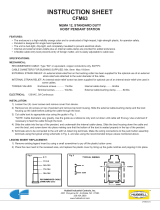
3) Cut cable boot to appropriate size using the guide in Fig. 1.
*NOTE: Cable diameters vary greatly. Use the guide as a reference only and cut down until cable will fit snug. Use a lubricant if
necessary to feed the cable through the boot.
4) Slide the cable into the top of the pendant, and underneath the internal cable-clamp. Slide the boot housing down the cable and
over the boot, and screw down into place making sure that the bottom of the boot is seated properly in the top of the pendant.
5) Terminate wire to be connected to the unit with UL listed ring terminals. Make the wiring connections to the push button assembly
terminals using the typical wiring schematic in Fig. 2, and also using the recommended torque values mentioned above.
6) Place cover on enclosure and tighten cover screws using the recommended torque values.
LEGEND INSERT REPLACEMENT:
1) Remove existing legend insert by using a small screwdriver to pry off the plastic button cover.
2) Place the new insert in the recessed area, and replace the plastic cover by lining up the guide notches and popping it into place.
COB2130214
Hubbell Industrial Controls, Inc.
4301 Cheyenne Dr., Archdale, NC 27263
336.434.2800
www.hubbell-icd.com
8-11
11-13.5
14.5-15.5
17.2-18.4
18.4-19.6
Fig. 1
RECOMMENDED CABLE
DIAMETERS (mm)
Fig. 2
CUSTOMER CONNECTIONS
1,3 POWER SOURCE
1,6 MAIN WINDING
4,5 STARING WINDING
4
1
5
2
6
3
7 8 9
UP
DOWN
/
