Page is loading ...

BD-Sensors-Str.1; 95199 Thierstein, Germany
Phone: +49 (0) 92 35 98 11 0 | www.bdsensors.de
© 2021 BD|SENSORS GmbH - All rights reserved.
Operating Manual
Probe for Marine and Offshore for IS-areas
DX14-LMK 457, DX14A-LMK 458,
DX14B-LMK 487, DX14B-LMK 487H, DX15A-LMK 458H
READ THOROUGHLY BEFORE USING THE DEVICE
KEEP FOR FUTURE REFERENCE
ID: BA_FS Schiff_Ex_E | Version: 03.2021.0
1. General information
1.1 Information on the operating manual
Adhere to the safety notes and operating instructions which
are given in the operating manual. Additionally, applicable
regulations regarding occupational safety, accident preven-
tion as well as national installation standards and engineer-
ing rules must be complied with!
For the installation, maintenance and cleaning of the device,
you must absolutely observe the relevant regulations and
stipulations on explosion protection (VDE 0160, VDE 0165
and EN 60079-14) as well as the occupational safety provi-
sions.
The device was constructed acc. to standards:
DX14: EN60079-0:2012+A11:2013,
EN60079-11:2012, EN60079-26:2007
DX14A: EN60079-0:2012+A11:2013,
EN60079-11:2012
DX14B: EN60079-0:2018,
EN60079-11:2012
IEC 60079-0: 2017 Edition 7
IEC 60079-11: 2011 Edition 6
DX15A: EN60079-0:2012+A11:2013,
EN60079-11:2012
This operating manual is part of the device, must be kept
nearest its location, always accessible to all employees.
– Technical modifications reserved –
1.2 Symbols used
Warning term
- Nature and source of danger
- Measures to prevent danger
Warning term Meaning
DANGER
- Immediate danger!
- Failure to observe will result in
death or serious injury.
WARNING
- Possible danger!
- Failure to observe may result in
death or serious injury.
CAUTION
- Dangerous situation!
- Failure to observe may result in
slight or moderate injury.
NOTE – Tips and information for the user in order to
ensure trouble-free operation.
1.3 Qualification of personnel
Installation, commissioning, operation, maintenance, de-
commissioning and disposal may be carried out only by
appropriately qualified specialist personnel.
Work on electrical components must be performed only by a
qualified electrician and in accordance with the applicable
regulations and guidelines.
1.4 Limitation of liability and warranty
Failure to observe the instructions or technical regulations,
improper use and use not as intended, alteration of or
damage to the device as well as incorrect installation of
signal connections or ground potential connections will result
in the forfeiture of warranty and liability claims.
1.5 Intended use
- The hydrostatic probes have been designed especially for
shipbuilding and offshore applications with rough environ-
mental and operation conditions. The probes are suitable
for level measurement of fluids or pasty media (no solids
and frozen media) in open tanks, containers or reservoirs.
As medium all fluids can be used which are compatible
with the materials of housing, sealing and cable. Based on
a rugged and reliable capacitive ceramic sensor the probe
is qualified for measuring small filling heights with high
accuracy. Typical areas of use are ballast tanks, fuel and
oil tanks as well as service and waste water tanks. The
probes as standard complies with the requirements of
DNV▪GL (Det Norske Veritas▪Germanischer Lloyd). The
certificates are available for download on our homepage:
http:// www.bdsensors.com
- This operating manual applies to devices with explosion
protection approval and is intended for the use in IS-areas.
A device has an explosion protection approval if this has
been specified in the purchase order and confirmed in our
order confirmation. In addition, the manufacturing label
contains the -symbol.
- It is the operator's responsibility to check and verify the
suitability of the device for the intended application. If any
doubts remain, please contact our sales department in
order to ensure proper usage. BD SENSORS is not liable
for any incorrect selections and their effects!
- The hydrostatic probe has to be used according to the
area of application specified above! In addition, it has to
be ensured, that this medium is compatible with the media
wetted parts.
- The technical data listed in the current data sheet are
engaging and must absolutely be complied with. If the
data sheet is not available, please order or download it
from our homepage. (http://www.bdsensors.com)
WARNING
Danger through incorrect use
- In order to avoid accidents, use the
device only in accordance with its
intended use.
1.6 Safety technical maximum values
DX14-LMK 457:
Ui = 28 V, Ii = 93 mA, Pi = 660 mW, Ci = 147 nF, Li = 5 µH;
plus cable inductivities 1 µH/m and
cable capacities 160 pF/m (for cable by factory)
application in zone 0 (patm 0.8 bar up to 1.1 bar): -20 ... 60 °C
application in zone 1 and higher: -25 ... 70 °C
DX14A-LMK 458
Ui = 28 V; Ii = 93 mA; Pi = 660 mW; Ci = 105 nF;
Li = 0 µH; 140 nF opposite GND;
plus cable inductivities 1 µH/m and
cable capacities 160 pF/m (for cable by factory)
application in zone 0 (patm 0.8 bar up to 1.1 bar): -20 ... 60 °C
application in zone 1 and higher: -25 ... 70 °C
DX14B-LMK 487 / DX14B-LMK 487 H:
Ui = 28 V; Ii = 93 mA; Pi = 660 mW; Ci = 49.2 nF/14 nF;
Li = 0 µH; 100 nF/27 nF opposite GND;
plus cable inductivities 1 µH/m and
cable capacities 160 pF/m (for cable by factory)
application in zone 0 (patm 0.8 bar up to 1.1 bar): -20 ... 60 °C
application in zone 1 and higher: -25 ... 65 °C
DX15A-LMK 458H:
Ui = 28 V; Ii = 93 mA; Pi = 660 mW; Ci = 94.6 nF;
Li = 0 µH; 110 nF opposite GND;
plus cable inductivities 1 µH/m and
cable capacities 160 pF/m (for cable by factory)
application in zone 0 (patm 0.8 bar up to 1.1 bar): -20 ... 60 °C
application in zone 1 and higher: -25 ... 70 °C
1.7 Package contents
Please verify that all listed parts are undamaged included in
the delivery and check for consistency specified in your
order:
- hydrostatic probe
- this operating manual
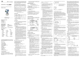
2. Product identification
The device can be identified by its manufacturing label. It
provides the most important data. By the ordering code the
product can be clearly identified.
Fig. 1 example of manufacturing label
The manufacturing label must not be removed from the
device!
3. Mechanical installation
3.1 Mounting and safety instructions
DANGER
Danger of death from electric shock
or explosion
- Always mount the device in a
depressurized and de-energized
condition!
- Install equipotential bonding along
the entire length of the line, both
inside and outside the explosion
hazard area.
- Do not install the device while there
is a risk of explosion.
- The technical data listed in the EC type-examination
certificate are engaging. If the certificate is not available,
please order or download it from our homepage.
(http://www.bdsensors.com)
- In case of increased danger of lightning strike or dam-
age by overvoltage, a stronger lightning protection
should be planned.
- Observe the limiting values specified in the EC type-
examination certificate. (Capacitance and inductance of
the connection cable are not included in the values.)
- Make sure that the entire interconnection of intrinsically
safe components remains intrinsically safe. The opera-
tor is responsible for the intrinsic safety of the overall
system (installation of intrinsic parts).
- Do not mount the device in a pneumatic flow rate!
- The probe must be installed in such a way that rubbing
or impact of the sensor head (sensor element), e. g.
against a tank wall, is prevented. It is also important to
consider the operating conditions such as flow condi-
tions. This applies especially to probes with cable outlet
and devices with a pipe extension with a length of more
than 2.8 m
- Excessive dust deposits (over 5 mm) and a complete
dust covering must be avoided for screw-in and flange
versions!
Handle this high-sensitive electronic precision
measuring device with care, both in packed and
unpacked condition!
There are no modifications/changes to be made on the
device.
Do not throw the package/device!
To avoid damaging the diaphragm, remove packaging
and protective cap directly before starting assembly.
The delivered protective cap has to be stored! Place the
protective cap on the pressure port again immediately
after disassembling.
Handle the unprotected diaphragm very carefully - it is
very sensitive and may be easily damaged.
Do not use any force when installing the device to
prevent damage of the device and the plant!
When placing the probe into operation or after mainte-
nance work, the probe has to be submerged slowly into
the medium! A rough immersion into the medium can
damage or destroy the diaphragm.
For installations outdoor and in damp areas following
these instructions for screw-in and flange versions:
- Please note that your application does not show a
dew point, which causes condensation and can
damage the pressure transmitter. There are spe-
cially protected pressure transmitters for these op-
erating conditions. Please contact us in such case.
- Choose an assembly position, which allows the
flow-off of splashed water and condensation.
- Turn the outgoing cable downwards. If the cable
has to be turned upwards, then point it downward
so the moisture can drain.
- Install the device in such a way that it is protected
from direct solar irradiation. Direct solar irradiation
can lead to the permissible operating temperature
being overstepped in the worst case. This is
prohibited for applications in IS-areas!
Take note for screw-in and flange transmitter that no
inadmissibly high mechanical stresses occur at the
pressure port as a result of the installation, since this
may cause a shifting of the characteristic curve or to the
demage.
In hydraulic systems, arrange the device such that the
pressure port points upwards. (venting)
Provide a cooling line when using the device in steam
piping.
3.2 General installation steps
- Carefully remove the pressure measuring device from
the package and dispose of the package properly.
3.3 Installation steps for probe
- Install the device according to your demands.
Usually, the probe is delivered without mounting acces-
sories. BD SENSORS offers different accessories on
request e.g. mounting clamp, terminal clamp or mount-
ing flange.
3.4 Installation steps for flange transmitter
- Please ensure that the mounting thread is clean and
free of damage.
- Check to ensure that the O-ring fits properly in the
groove.
- Screw in the mounting thread of the transmitter in the
transmitter flange.
- Next, tighten it by an open-end wrench. (approx. 25 Nm)
- Install the flange according to your demands.
If a new transmitter flange is needed, it can be ordered
from BD SENSORS.
3.5 Installation steps for screw-in transmitter
- Please ensure that the mounting thread is clean and
free of damage.
- Check to ensure that the O-ring fits properly in the
groove.
- Ensure that the sealing surface of the taking part e.g.
welding socket is perfectly smooth and clean.
- Screw the device in the corresponding thread by hand.
- Next, tighten it by an open-end wrench. (approx. 25 Nm;)
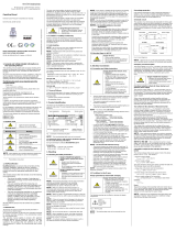
3.6 Removing the protection cap (for probe)
For the protection of the diaphragm, some of the probes
have a plugged-on protection cap. If the device shall be used
in high-viscosity media such as sludge, a removal of the cap
before start-up is necessary. Thus, the sensor becomes flush
and the medium will attain quickly to the diaphragm.
If it is necessary for your application to remove the
protection cap, this has to be done with utmost care. To
prevent a damage of the diaphragm, please follow the
instructions below:
Removal by hand
- Hold the probe in a way that the protection cap points
upwards.
- Hold the probe with one hand on the sensor section (1).
- Remove the protection cap (2) with the other hand.
Removal with a tool (recommended)
- Hold the probe in a way that the protection cap points
upwards.
- Slide a small tool such as a screwdriver (8) straight
through two opposite drill holes in the protective cap (2).
- Lever it off by moving up the handle of the screwdriver.
Make sure that the sensor (7) under the protection cap
will not be damaged!
4. Special regulations for IS-areas
4.1 Protection against electrostatic charge hazards
DANGER
Danger of death from explosion
- Explosion hazard due to spark
formation from electrostatic charg-
ing of plastic components.
-
If devices are equipped with a cable
outlet, the connection cable routing
must be fixed.
- Do not clean the device and, if
applicable, the connection cable, in
a dry state! Use a moist cloth, for
example.
Different types of the device partially consist of chargeable
plastic components. These are, in particular, the carrying and
connection cables. A potential electrostatic charge presents
the danger of spark generation and ignition. An electrostatic
charge must therefore be absolutely prevented.
The following warning sign is, if applicable, attached to the
probe. It points once more to the hazard of electrostatic
charging.
Fig. 3 warning sign
The warning sign must not be removed from the device!
4.2 Hit or friction sparks device in titanium
DANGER
Danger of death from explosion
- Danger of devices in titanium
caused by hit or friction sparks by
contact with other bodies or objects
avoid commuting or swinging of the
probes.
-
Avoid commuting or swinging of the
probe.
4.3 Overvoltage protection
If the probe is used as electrical equipment of category 1 G,
then a suitable overvoltage protection device must be
connected in series (attend the valid regulations for operating
safety as well as EN60079-14).
4.4 Schematic circuit
The operation of an intrinsically safe probe in intrinsic safe
areas requires special care when selecting the necessary
Zener barrier or transmitter repeater devices to allow the
utilization of the device’s properties to the full extent. The
following diagram shows a typical arrangement of power
supply, Zener barrier and probe.
Fig. 4 Circuit diagrams
! Please pay attention to item (17) of the type examination
certificate, which stipulates special conditions for intrinsi-
cally safe operation.
4.5 Exemplary circuit description
The supply voltage of e.g. 24 VDC provided by the power
supply is led across the Zener barrier. The Zener barrier
contains series resistances and breakdown diodes as
protective components. Subsequently, the operating voltage
is applied to the transmitter and, depending on the pressure,
a particular signal current flows.
DANGER
Danger of death from explosion
- Operation of intrinsically safe devic-
es as zone-0 equipment only with
ungrounded and galvanically isolat-
ed power supply
4.6 Selection criteria for Zener barriers and galvanic
power supply
The minimum supply voltage VS min of the transmitter must
not fall short. The minimum supply voltage has been defined
in the respective product-specific data sheet under "Output
signal / supply".
When using a galvanically insulated amplifier with linear
bonding, note that the terminal voltage of the transmitter will
decrease like it does with a Zener barrier. Furthermore, you
have to note that the supply will additionally decrease with an
optionally used signal amplifier.
4.7 Test criteria for the selection of the Zener barrier
In order not to fall below VS min, it is important to verify which
minimum supply voltage is available at full level control of the
transmitter. The full level control, i.e. a maximum or nominal
output signal (20 mA), can be reached by applying the
maximum physical input signal (pressure).
The technical data of the barrier will usually provide the
information needed for the selection of the Zener barrier.
However, the value can also be calculated. If a maximum
signal current of 0.02 A is assumed, then – according to
Ohm’s law – a particular voltage drop will result from the
series resistance of the Zener barrier. This voltage drop is
subtracted by the voltage of the power supply and as a
result, the terminal voltage is obtained which is applied on
the transmitter at full level control. If this voltage is smaller
than the minimum supply voltage, another barrier or a higher
supply voltage have to be chosen.
When selecting the supplied devices / Zener barrier, the
maximum operating conditions according to the EC
type-examination certificate must be observed. When
assessing these, refer to their current data sheets to
ensure that the entire interconnection of intrinsically
safe components remains intrinsically safe.
4.8 Calculation example for the selection of the Zener
barrier
The nominal voltage of the power supply in front of the Zener
barrier is 24 VDC ± 5%. This results in:
- greatest supply voltage: VSup max = 24 V * 1.05 = 25.2 V
- smallest supply voltage: VSup min = 24 V * 0.95 = 22.8 V
The series resistance of the Zener barrier is listed with
295 ohm. The following values must still be calculated:
- Voltage drop at the barrier:
Vab barrier = 295 Ω * 0.02 A = 5.9 V (with full conduction)
- Terminal voltage at the transmitter with Zener barrier:
VKl = VSup min – Vab barrier = 22.8 V – 5.9 V = 16.9 V
- Minimum supply voltage of the transmitter
(according to data sheet):
VKl min = 12 VDC (corresponding to VB min)
Condition:
VKl ≥ VKl min
Result:
The terminal voltage of the probe with Zener barrier lies at
16.9 V and is therefore higher than the minimum supply
voltage of the probe which lies at 12 VDC. This means, the
Zener barrier has been selected correctly regarding the
supply voltage.
Note that no line resistances have been listed in this
calculation. However, these will lead to an additional
voltage drop that must be taken into account.
5. Electrical Installation
DANGER
Danger of death from electric
shock
- Switch off the power supply before
installing the device!
DANGER
Danger of death from explosion
- Risk of explosion if the operating
voltage is too high (max. 28VDC)!
- Connect the device as described
in the user manual
Establish the electrical connection of the device according to
the technical data shown on the manufacturing label, the
following table and the wiring diagram.
Pin configuration:
Electrical connection
cable colours (IEC 60575)
Supply +
Supply −
Supply T+ (with Pt 100)
Supply T– (with Pt 100)
Supply T– (with Pt 100)
WH (white)
BN (brown)
YE (yellow)
GY (grey)
PK (pink)
Shield
GNYE (green-yellow)
Wiring diagram:
2-wire-system current (pressure) / 3-wire-system (temp.)
2-wire-system (current) HART
A minimum static bending radius has to be complied
with. For static installation use the 10-fold cable diame-
ter, for dynamic applications use the 20-fold diameter.
Prevent the damage or removal of the PTFE filter which
is fixed over the end of the air tube on devices with
cable outlet and integrated air tube.
Fig.
2 removal of protection cap
p
supply +
supply –
V
S
I
ordering code
type designation
nominal
pressure
range
signal
serial number
EC type examination certificate
number; explosion marking
safety specific
technical max. values
LMK 487(H)
transmitter
+V
S
V
S
Zener barrier
+V
S
-V
S
power supply
probe
amplifier
supply
shielded cable
IS-area
secure area
supply V
S
+
supply V
S
−
supply T+
supply T−
supply T−
V
S
p
I
option Pt 100-
temperature
element
0637
LMK 458H
LMK 487H:

For identification, the intrinsically safe cables are
marked with light blue shrink tubing (over the cable in-
sulation). If the cable has to be modified (e. g. short-
ened) and the marking at the cable end has been lost in
the process, it must be restored (for example, by mark-
ing it again with light blue shrink tubing or an appropri-
ate identification sign).
For the electrical connection a shielded and twisted
multicore cable has to be used.
For probes, the cable shield must be connected to earth
potential. Use the appropriate grounding clamps for this.
Pay attention to a low-impedance connection. Avoid
potential differences (earth potential) between
measuring and connection points, because this can lead
to a defect in the probe. To avoid this, use a suitable
connection technology or suitable equipotential bonding.
If a transition is desired from a probe cable with gauge
tube to a cable without gauge tube, we recommend our
terminal box KL 1 or KL 2.
Usually, the required cable is included in the scope of
delivery. If it is although necessary to connect an exist-
ing or special cable, the total resistance will increase.
For applications, where this additional resistance of the
connecting cable could cause problems, this cable has
to be checked with the following calculation.
Al
R
L
⋅⋅
=2
ρ
with RL: resistance of connecting cable in Ω
ρ: specific resistance in Ω mm²/m
l: cable length in m
A: cross section of conductor in mm²
( )
A
0.02
R...
RRV
loadL2L1tot
⋅+++=
with Vtot: total voltage drop
Rload: load resistance (to be taken out of the
current data sheet)
following condition has to be fulfilled:
minStotS
VVV +>
with VS: planned supply voltage
VS min: minimal supply voltage (to be taken out of
the current data sheet)
6. HART Communication (in H-devices)
DANGER
Danger of death from explosion
- The intrinsically safe circuit for
connecting a HART communica-
tions interface (HART communi-
cator or HART modem) may be
broken only if there is no risk of
an explosion.
The analogue output signal is overridden by an additional
signal according to the HART-specification. The device can
be configured via a HART-communication device. There-
fore, we suggest our programming kit CIS 150 (available as
accessory). It consists of HART-modem, connecting cables
as well as configuration software and allows a simple and
time-saving configuration of all parameters. (The software is
compatible with all Windows-systems from Windows 98 and
higher.)
To ensure a trouble-free operation the following require-
ments should be fulfilled:
maximal cable length between device and power supply:
VVV
CCR
L
36
max
10401065 ⋅
−
⋅
⋅
=
whereas Lmax: maximum length of cable in [m]
RV: resistance of the cable together with
the load resistance in [Ω]
CV: capacity of the cable in [pF/m]
resistance R:
Ω
−
=024.0 12U
R
whereas U: power supply in [VDC]
The resistance must be at least 240 Ω.
7. Commissioning
DANGER
Danger of death from explosion
- Explosion hazard if the operating
voltage is too high (max. 28 VDC)!
- Operate the device only within the
specification! (data sheet)
The device has been installed properly
The device does not have any visible defect
The device is operated within the specification.
(see data sheet and EC type-examination certificate)
In case of highly precise devices with an accuracy of
0.1 % FSO, a microcontroller-controlled electronic system is
used for signal processing. This electronic system is used for
signal improvement. Due to the principle, the processing of
measured values requires a longer time than with purely
analogue sensors, which only comprise amplification circuit-
ry. Due to the longer processing time, the output signal
follows the measured value not continuously but in jumps. In
case of relatively stable and slowly changing measured
values, this property plays a minor role. Compare this with
the information on the adjusting time in the data sheet.
8. Maintenance
DANGER
Danger of death
- from airborne parts, leaking fluids,
electric shock
- Always service the device in a
depressurized and de-energized
condition!
WARNING
Danger of injury from aggressive
fluids or pollutants
- Depending on the measured medi-
um, this may constitute a danger to
the operator.
- Wear suitable protective clothing,
e.g. gloves, safety goggles.
In principle, this device is maintenance-free. If desired, the
housing of the device can be cleaned using a damp cloth
and non-aggressive cleaning solutions without supply.
With certain media, however, the diaphragm may be polluted
or coated with deposit. It is recommended to define corre-
sponding service intervals for control. After placing the
device out of service correctly, the diaphragm can be
cleaned carefully with a non-aggressive cleaning solution
and a soft brush or sponge. If the diaphragm is calcified, it is
recommended to send the device to BD SENSORS for
decalcification. Please read therefore the chapter “Repair”
below.
A false cleaning of the device can cause an irreparable
damage on the diaphragm. Therefore, never use point-
ed objects or pressured air for cleaning the diaphragm.
9. Troubleshooting
DANGER
Danger of death
- from airborne parts, leaking
fluids, electric shock
- If malfunctions cannot be re-
solved, put the device out of ser-
vice and proceed according to
sections 10 up to 12!
DANGER
Danger of death from explosion
- As a matter of principle, work on
energized parts, except for intrin-
sically safe circuits, is prohibited
while there is an explosion haz-
ard.
- Additionally, the operator is
obligated to observe the infor-
mation concerning operation and
maintenance work on the warning
signs possibly affixed to the
device
In case of malfunction, it must be checked whether the
device has been correctly installed mechanically and electri-
cally. Use the following table to analyse the cause and
resolve the malfunction, if possible.
Fault: no output signal
Possible cause
Fault detection / remedy
connected incorrectly
Checking of connections
Conductor/wire breakage
Checking of all line connec-
tions.
Defective measuring device
(signal input)
Checking of ammeter (minia-
ture fuse) or of analogue input
of your signal processing unit
Fault: analogue output signal too low/small
Possible cause
Fault detection / remedy
Load resistance too high
Checking of load resistance
(value)
Supply voltage too low
Checking of power pack
output voltage
Defective energy supply
Checking of the power pack
and the supply voltage being
applied to the device
Fault: slight shift of the output signal
Possible cause
Fault detection / remedy
Diaphragm of measuring
cell is severely contami-
nated
Cleaning using a non-
aggressive cleaning solution
and soft paintbrush or sponge
Diaphragm of measuring
cell is calcified or crusted
Recommendation: Have the
decalcification or cleaning
performed by BD|SENSORS
Fault: large shift of the output signal
Possible cause
Fault detection / remedy
Diaphragm of measuring
cell is damaged (caused
by overpressure or
mechanically)
Checking of diaphragm; when
damaged, send the device to
BD|SENSORS for repair
Fault: wrong or no output signal
Possible cause
Fault detection / remedy
Cable damaged
mechanically,
thermally or chemically
Checking of cable; pitting
corrosion on the stainless-
steel housing as a result of
damage on cable; when
damaged, send the device to
BD|SENSORS for repair
10. Placing out of service
DANGER
Danger of death
- from airborne parts, leaking fluids,
electric shock
- Disassemble the device in a
depressurized and de-energized
condition!
WARNING
Danger of injury from aggressive
media or pollutants
- Depending on the measured
medium, this may constitute a
danger to the operator.
- Wear suitable protective clothing,
e.g. gloves, goggles.
After dismounting, mechanical connections must be
fitted with protective caps.
11. Service/Repair
Information on service / repair:
- www.bdsensors.de
- service phone: +49 (0) 92 35 98 11 0
11.1 Recalibration
During the life-time of a transmitter, the value of offset and
span may shift. As a consequence, a deviating signal value
in reference to the nominal pressure range starting point or
end point may be transmitted. If one of these two phenome-
na occurs after prolonged use, a recalibration is recom-
mended to ensure furthermore high accuracy
11.2 Return
WARNING
Danger of injury from aggressive
fluids or pollutants
- Depending on the measured
medium, this may constitute a
danger to the operator.
- Wear suitable protective clothing,
e.g. gloves, goggles
Before every return of your device, whether for recalibration,
decalcification, modifications or repair, it has to be cleaned
carefully and packed shatter-proofed. You have to enclose a
notice of return with detailed defect description when sending
the device. If your device came in contact with harmful
substances, a declaration of decontamination is additionally
required.
Appropriate forms can be downloaded from our homepage.
Download these by accessing www.bdsensors.com or
request them:
in[email protected] | phone: +49 (0) 92 35 / 98 11 0
In case of doubt regarding the fluid used, devices without a
declaration of decontamination will only be examined after
receipt of an appropriate declaration!
12. Disposal
WARNING
Danger of injury from aggressive
fluids or pollutants
- Depending on the measured
medium, this may constitute a
danger to the operator.
- Wear suitable protective clothing,
e.g. gloves, goggles
The device must be disposed of according to the
European Directive 2012/19/EU (waste electrical
and electronic equipment). Waste equipment
must not be disposed of in household waste!
13. Warranty Terms
The warranty terms are subject to the legal warranty period
of 24 months, valid from the date of delivery. If the device is
used improperly, modified or damaged, we will rule out any
warranty claim. vA damaged diaphragm will not be accepted
as a warranty case. Likewise, there shall be no entitlement to
services or parts provided under warranty if the defects have
arisen due to normal wear and tear.
14. EU Declaration of conformity / CE
The delivered device fulfils all legal requirements. The
applied directives, harmonised standards and documents are
listed in the EC declaration of conformity, which is available
online at: http://www.bdsensors.com.
Additionally, the operational safety is confirmed by the CE
sign on the manufacturing label.
DX14-LMK 457:
DX14A-LMK 458:
Fig. 5 configurationsoftware
DX14B-LMK 487 / DX14B-LMK 487 H:
DX15A-LMK 458H:
/