Page is loading ...

BD-Sensors-Str.1; 95199 Thierstein, Germany
Phone: +49 (0) 92 35 98 11 0 | www.bdsensors.de
© 2022 BD|SENSORS GmbH - All rights reserved.
Operating Manual
Probe for Marine and Offshore
LMK 457, LMK 458, LMK 458H, LMK 487, LMK 487H
READ THOROUGHLY BEFORE USING THE DEVICE
KEEP FOR FUTURE REFERENCE
ID: BA_FS Schiff_E | Version: 07.2022.0
1. General and safety-related information on
this operating manual
This operating manual enables safe and proper handling of the
product, and forms part of the device. It should be kept in close
proximity to the place of use, accessible for staff members at
any time.
All persons entrusted with the mounting, installation, putting into
service, operation, maintenance, removal from service, and
disposal of the device must have read and understood the
operating manual and in particular the safety-related information.
Complementary to this operating manual the current data sheet
has to be adhered to.
Download this by accessing www.bdsensors.com or request it:
[email protected] | phone: +49 (0) 92 35 / 98 11 0
In addition, the applicable accident prevention regulations,
safety requirements, and country-specific installation standards
as well as the accepted engineering standards must be
observed.
1.1 Symbols used
Warning word
- Type and source of danger
- Measures to avoid the danger
Warning word
Meaning
DANGER
- Imminent danger!
- Non-compliance will result in
death or serious injury.
WARNING
- Possible danger!
- Non-compliance may result in
death or serious injury.
CAUTION
- Hazardous situation!
- Non-compliance may result in
minor or moderate injury.
NOTE - draws attention to a possibly hazardous situation that
may result in property damage in case of non-compliance.
✓ Precondition of an action
1.2 Staff qualification
Qualified persons are persons that are familiar with the
mounting, installation, putting into service, operation,
maintenance, removal from service, and disposal of the product
and have the appropriate qualification for their activity.
This includes persons that meet at least one of the following
three requirements:
- They know the safety concepts of metrology and
automation technology and are familiar therewith as
project staff.
- They are operating staff of the measuring and
automation systems and have been instructed in the
handling of the systems. They are familiar with the
operation of the devices and technologies described in
this documentation.
- They are commissioning specialists or are employed in
the service department and have completed training that
qualifies them for the repair of the system. In addition,
they are authorized to put into operation, to ground, and
to mark circuits and devices according to the safety
engineering standards.
All work with this product must be carried out by qualified
persons!
1.3 Intended use
The device is intended for converting the physical parameter of
pressure into an electric signal. It has to be used only for this
purpose, considering the following information.
The hydrostatic probes have been designed especially for
shipbuilding and offshore applications with rough environmental
and operation conditions. The probes are suitable for level
measurement of fluids or pasty media (no solids and frozen
media) in open tanks, containers, or reservoirs. Based on a
rugged and reliable capacitive ceramic sensor the probe is
qualified for measuring small filling heights with high accuracy.
Typical areas of use are ballast tanks, fuel, and oil tanks as well
as service and waste water tanks. The probes as standard
complies with the requirements of DNV (Det Norske Veritas).
The certificates are available for download on our homepage:
http:// www.bdsensors.de
Permissible measuring and cleaning media are gases or liquids,
which are compatible with the media wetted parts of the device
(according to data sheet) and your system. This must be
ensured for the application.
The user must check whether the device is suited for the
selected use. In case of doubt, please contact our sales
BD|SENSORS assumes no liability for any wrong selection and
the consequences thereof!
The technical data listed in the current data sheet are engaging
and must absolutely be complied with. If the data sheet is not
available, please order or download it from our homepage:
http://www.bdsensors.de
1.4 Incorrect use
WARNING
Danger through incorrect use
- Only use the device in permissible
media and in accordance with its
intended use.
- Do not use the device as a ladder or
climbing aid.
- The device must not be altered or
modified in any way.
- BD|SENSORS is not liable for damage
caused by improper or incorrect use.
1.5 Limitation of liability and warranty
Failure to observe the instructions or technical regulations,
improper use and use not as intended, and alteration of or
damage to the device will result in the forfeiture of warranty
and liability claims.
1.6 Safe handling
NOTE - Do not use any force when installing the device to
prevent damage of the device and the plant!
NOTE - Treat the device with care both in the packed and
unpacked condition!
NOTE - Do not throw or drop the device!
NOTE - Excessive dust accumulation and complete coverage
with dust must be prevented!
NOTE - The device is state-of-the-art and is operationally
reliable. Residual hazards may originate from the device if it is
used or operated improperly.
1.7 Scope of delivery
Check that all parts listed in the scope of delivery are included
free of damage, and have been delivered according to your
purchase order:
- hydrostatic probe
- mounting instruction
1.8 UL approval (for devices with UL marking)
The UL approval was effected by applying the US standards,
which also conform to the applicable Canadian standards on
safety.
Observe the following points so that the device meets the
requirements of the UL approval:
- only indoor usage
- maximum operating voltage: according to data sheet
- The device must be operated via a supply with energy
limitation (acc. to UL 61010) or an NEC Class 2 energy
supply.
2. Product identification
The device can be identified by means of the manufacturing
label with order code. The most important data can be gathered
therefrom.
Fig. 1 Example of manufacturing label
NOTE - The manufacturing label must not be removed!
3. Mounting
3.1 Mounting and safety instructions
DANGER
Danger of death from airborne parts,
leaking fluid, electric shock
- Always mount the device in a
depressurized and de-energized
condition!
DANGER
Danger of death from improper
installation
- Installation must be performed only by
appropriately qualified persons who
have read and understood the
operating manual.
NOTE - Do not remove the packaging or protective caps of the
device until shortly before the mounting procedure, in order to
exclude any damage to the diaphragm and the threads!
Protective caps must be kept! Dispose of the packaging
properly!
NOTE - If there is increased risk of damage to the device by
lightning strike or overvoltage, increased lightning protection
must additionally be provided!
NOTE - Treat any unprotected diaphragm with utmost care;
this can be damaged very easily.
NOTE for screw-in and flange version:
- When installing the device, avoid high mechanical stresses on
the pressure port! This will result in a shift of the characteristic
curve or to damage.
- In hydraulic systems, position the device in such a way that
the pressure port points upward (ventilation).
- Do not mount the device in a pneumatic flow rate!
- Provide a cooling line when using the device in steam piping
and clarify the material compatibility.
- The measuring point must be designed in such a way that
cavitation and pressure surges are avoided.
- If a gauge pressure measuring device is installed with the
pressure port pointing upwards, ensure that no liquid drains
off on the device. This could result in humidity and dirt
blocking the gauge reference in the housing and could lead to
malfunctions.
- The permissible tightening torque depends on the conditions
on site (material and geometry of the mounting point). The
specified tightening torques for the probe must not be
exceeded!
NOTES - for mounting outdoors or in a moist environment
(for screw-in and flange version):
- Please note that your application does not show a dew point,
which causes condensation and can damage the probe.
There are specially protected pressure measuring devices for
these operating conditions. Please contact us in such case.
- Connect the device electrically straightaway after mounting or
prevent moisture penetration, e.g. by a suitable protective
cap. (The ingress protection specified in the data sheet
applies to the connected device.)
- Select the mounting position such that splashed and
condensed water can drain off. Stationary liquid on sealing
surfaces must be excluded!
- The outgoing cable must be routed downwards. If the cable
needs to be routed upwards, this must be done in an initially
downward curve.
- Mount the device such that it is protected from direct solar
radiation. In the most unfavourable case, direct solar radiation
leads to the exceeding of the permissible operating
temperature.
- For devices with gauge reference in the housing (small hole
next to the electrical connection), install the device in such a
way, that the gauge reference is protected from dirt and
moisture. Should the device be exposed to fluid admission,
the functionality will be blocked by the gauge reference. An
exact measurement in this condition is not possible.
Furthermore, this can lead to damages on the device.
3.2 Mounting steps for probes
✓ mounting accessory is available (as standard, the probe is
supplied without fastening material; mounting clamps,
terminal clamps and mounting flanges are available as
accessories from BD|SENSORS)
Fasten the probe properly according to your requirements.
NOTE - Always immerse the device slowly into the fluid to be
measured! If the probe strikes the liquid surface, the diaphragm
could be damaged or destroyed.
3.2.1 Removal of protective cap (if necessary)
For the protection of the diaphragm, some of the probes have a
plugged-on protection cap. If the device shall be used in high-
viscosity media such as sludge, a removal of the cap before
start-up is necessary. Thus, the sensor becomes flush, and the
medium will attain quickly to the diaphragm.
Removal by hand
1. Hold the probe in a way that the protection cap points
upwards.
2. Hold the probe with one hand on the sensor section (1).
3. Remove the protection cap (2) with the other hand.
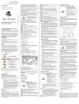
Removal with a tool (recommended)
Fig.2 Removal of protection cap
1. Hold the probe in a way that the protection cap points
upwards.
2. Slide a small tool such as a screwdriver (8) straight through
two opposite drill holes in the protective cap (2).
3. Lever it off by moving up the handle of the screwdriver.
NOTE - Make sure that the sensor (7) under the protection cap
will not be damaged!
3.2.2 Cable protection (optional)
According to order, the probe was supplied with cable
protection; if the probe was prepared for mounting with stainless
steel pipe (optional), the customer must affix a cable protection
themselves.
3.3 Mounting steps for flange version
✓ The mounting thread is clean and undamaged.
✓ The O-ring is undamaged and seated in the designated
groove at the probe end.
1. Screw the mounting thread of the probe into the probe
flange by hand.
2. Tighten the device using a suitable open-end wrench.
(approx. 25 Nm)
3. Mount the flange according to your requirements.
If you need a new probe flange, this can be ordered from
BD|SENSORS as an accessory.
3.4 Mounting steps for screw-in version
✓ The mounting thread is clean and undamaged.
✓ The O-ring is undamaged and seated in the designated
groove at the probe end.
✓ The sealing surface of the taking part e.g. welding socket is
perfectly smooth and clean.
1 Screw the device into the corresponding thread by hand.
2 Tighten it using a suitable open-end wrench.
G3/4": approx. 15 Nm
G1": approx. 20 Nm
G1 1/2": approx. 25 Nm
4. Electrical connection
4.1 Connection and safety instructions
DANGER
Danger of death from electric shock
- Always mount the device in a
depressurized and de-energized
condition!
✓ The supply corresponds to protection class III (protective
insulation).
NOTE - Use a shielded and twisted multicore cable for the
electrical connection.
NOTE - When routing the cable, following bending radiuses
have to be complied with:
static installation: 10-fold cable diameter
dynamic application: 20-fold cable diameter
NOTE - The PTFE filter, located at the cable end on the air
tube, must neither be damaged nor removed.
4.2 Electrical installation
Connect the device electrically according to the information
specified on the manufacturing label, the following table, and the
connection circuit diagram.
Pin configuration:
Electrical connections
cable colours (IEC 60757)
Supply +
Supply -
Supply T+ (with Pt 100)
Supply T– (with Pt 100)
Supply T– (with Pt 100)
WH (white)
BN (brown)
YE (yellow)
GY (grey)
PK (pink)
Shield
GNYE (green-yellow)
Wiring diagrams:
2-wire-system current (pressure) / 3-wire-system (temperature)
2-wire system (current) HART
NOTE - With shielded cables, the cable shield must be
connected to earth potential. Use the appropriate grounding
clamps for this. Pay attention to a low-impedance connection.
Avoid potential differences (earth potential) between measuring
and connection points, because this can lead to a defect in the
probe. To avoid this, use a suitable connection technology or
suitable equipotential bonding.
NOTE - The cable contains a ventilation tube for pressure
equalization. Route the end of the cable into an area or suitable
connection box which is as dry as possible and free from
aggressive gases, in order to prevent any damage.
NOTE - Usually, the required cable is included in the scope of
delivery. If it is although necessary to connect an existing or
special cable, the total resistance will increase. For applications,
where this additional resistance of the connecting cable could
cause problems, this cable has to be checked with the following
calculation.
Al
RL
=2
with RL: resistance of connecting cable in Ω
ρ: specific resistance in Ω mm²/m
l: cable length in m
A: cross section of conductor in mm²
( )
A0.02R...RRV loadL2L1tot +++=
with Vtot: total voltage drop
Rload: load resistance
(to be taken out of the current data sheet)
following condition has to be fulfilled:
minStotS VVV +
with VS: planned supply voltage
VS min: minimal supply voltage
(to be taken out of the current data sheet)
4.3 HART communication (for H-Devices)
The analogue output signal is overridden by an additional signal
according to the HART-specification. The device can be
configured via a HART-communication device. Therefore, we
suggest our programming kit CIS-G (available as accessory). It
consists of HART-modem, connecting cables as well as
configuration software and allows a simple and time-saving
configuration of all parameters. (The software is compatible with
all Windows-systems from Windows 98 and higher.)
✓ for trouble-free operation, the following requirements are
fulfilled:
maximal cable length between device and power supply:
VVV CCR
L36
max 10401065
−
=
with Lmax: maximum length of cable in [m]
RV: resistance of the cable together with
the load resistance in []
CV: capacity of the cable in [pF/m]
resistance R:
−
=024.0 12U
R
with U: power supply in [VDC]
The resistance must be at least 240 .
5. Commissioning
DANGER
Danger of death from airborne parts,
leaking fluid, electric shock
- Operate the device only within the
specification! (according to data sheet)
✓ The device has been installed properly.
✓ The device does not have any visible defect.
In case of highly precise devices with an accuracy of
0.1 % FSO, a microcontroller-controlled electronic system is
used for signal processing. This electronic system is used for
signal improvement. Due to the principle, the processing of
measured values requires a longer time than with purely
analogue sensors, which only comprise amplification circuitry.
Due to the longer processing time, the output signal follows the
measured value not continuously but in jumps. In case of
relatively stable and slowly changing measured values, this
property plays a minor role. Compare this with the information
on the adjusting time in the data sheet.
6. Maintenance
DANGER
Danger of death from airborne parts,
leaking fluids, electric shock
- Always service the device in a
depressurized and de-energized
condition!
WARNING
Danger of injury from aggressive fluids
or pollutants
- Depending on the measured medium,
this may constitute a danger to the
operator.
- Wear suitable protective clothing
e.g. gloves, safety goggles.
If necessary, clean the housing of the device using a
moist cloth and a non-aggressive cleaning solution.
During the cleaning processes, note the compatibility of the
cleaning media used in combination with the media-wetted
materials of the pressure measuring devices. Permissible
concentrations and temperatures must be observed.
Verification/validation by the user is essential.
Deposits or contamination may occur on the diaphragm/
pressure port in case of certain media. Depending on kind and
quality of the process, suitable cyclical maintenance intervals
must be specified by the operator. As part of this, regular checks
must be carried out regarding corrosion, damage of
diaphragm/seal(s) and signal shift. A periodical replacement of
the seal(s) may be necessary.
If the diaphragm is calcified, it is recommended to send the
device to BD|SENSORS for decalcification. Please note the
chapter ″Service / repair″ below.
NOTE - Wrong cleaning or improper touch may cause an
irreparable damage on the diaphragm. Therefore, never use
pointed objects or pressured air for cleaning the diaphragm.
p
Supply +
Supply –
VS
I
Supply VS+
Supply VS−
Supply T+
Supply T−
Supply T−
VS
P
I
option Pt 100-
temperature
element
LMK 458
LMK 458H,
LMK 487H:
Fig. 3 configuration software
Type designation Ordering code Serial number

7. Troubleshooting
DANGER
Danger of death from airborne parts,
leaking fluids, electric shock
- If malfunctions cannot be resolved, put
the device out of service (proceed
according to chapter 8 up to 10)
In case of malfunction, it must be checked whether the device
has been correctly installed mechanically and electrically. Use
the following table to analyse the cause and resolve the
malfunction, if possible.
Fault: no output signal
Possible cause
Fault detection / remedy
Connected incorrectly
Checking of connections
Conductor/wire breakage
Checking of all line
connections.
Defective measuring device
(signal input)
Checking of ammeter
(miniature fuse) or of analogue
input of your signal processing
unit
Fault: analogue output signal too low
Possible cause
Fault detection / remedy
Load resistance too high
Checking of load resistance
(value)
Supply voltage too low
Checking of power supply
output voltage
Defective energy supply
Checking of the power supply
and the supply voltage being
applied to the device
Fault: slight shift of the output signal
Possible cause
Fault detection / remedy
Diaphragm of senor is
severely contaminated,
calcified or crusted
Checking of diaphragm; if
necessary, send the device to
BD|SENSORS for cleaning
Fault: large shift of the output signal
Possible cause
Fault detection / remedy
Diaphragm of sensor is
damaged (caused by
overpressure or mechanically)
Checking of diaphragm; when
damaged, send the device to
BD|SENSORS for repair
Fault: wrong or no output signal
Possible cause
Fault detection / remedy
Cable damaged mechanically,
thermally, or chemically
Checking of cable; pitting
corrosion on the stainless-steel
housing as a result of damage
on cable; when damaged, send
the device to BD|SENSORS for
repair
8. Removal from service
DANGER
Danger of death from airborne parts,
leaking fluids, electric shock
- Disassemble the device in a
depressurized and de-energized
condition!
WARNING
Danger of injury from aggressive
media or pollutants
- Depending on the measured medium,
this may constitute a danger to the
operator.
- Wear suitable protective clothing
e.g. gloves, goggles.
NOTE - After dismounting, mechanical connections must be
fitted with protective caps.
9. Service / repair
Information on service / repair:
- www.bdsensors.de
- Service phone: +49 (0) 92 35 98 11 0
9.1 Recalibration
During the life-time of a probe, the value of offset and span may
shift. As a consequence, a deviating signal value in reference to
the nominal pressure range starting point or end point may be
transmitted. If one of these two phenomena occurs after
prolonged use, a recalibration is recommended to ensure
furthermore high accuracy.
9.2 Return
WARNING
Danger of injury from aggressive
media or pollutants
- Depending on the measured medium,
this may constitute a danger to the
operator.
- Wear suitable protective clothing
e.g. gloves, goggles.
Before every return of your device, whether for recalibration,
decalcification, modifications or repair, it has to be cleaned
carefully and packed shatter-proofed. You have to enclose a
notice of return with detailed defect description when sending
the device. If your device came in contact with harmful
substances, a declaration of decontamination is additionally
required. Appropriate forms can be downloaded from our
homepage. Download these by accessing www.bdsensors.de or
request them:
[email protected] | phone: +49 (0) 92 35 / 98 11 0
In case of doubt regarding the fluid used, devices without a
declaration of decontamination will only be examined after
receipt of an appropriate declaration!
10. Disposal
WARNING
Danger of injury from aggressive
media or pollutants
- Depending on the measured medium,
this may constitute a danger to the
operator.
- Wear suitable protective clothing
e.g. gloves, goggles.
The device must be disposed of according to the
European Directive 2012/19/EU (waste electrical
and electronic equipment). Waste equipment must
not be disposed of in household waste!
NOTE - Dispose of the device properly!
11. Warranty terms
The warranty terms are subject to the legal warranty period of
24 months, valid from the date of delivery. If the device is used
improperly, modified, or damaged, we will rule out any warranty
claim. A damaged diaphragm will not be accepted as a warranty
case. Likewise, there shall be no entitlement to services or parts
provided under warranty if the defects have arisen due to normal
wear and tear.
12. EU declaration of conformity / CE
The delivered device fulfils all legal requirements. The applied
directives, harmonised standards and documents are listed in
the EC declaration of conformity, which is available online at:
http://www.bdsensors.de.
Additionally, the operational safety is confirmed by the CE sign
on the manufacturing label.
Notes:
__________________________________________________________________________________________________
__________________________________________________________________________________________________
__________________________________________________________________________________________________
__________________________________________________________________________________________________
__________________________________________________________________________________________________
__________________________________________________________________________________________________
__________________________________________________________________________________________________
__________________________________________________________________________________________________
__________________________________________________________________________________________________
__________________________________________________________________________________________________
__________________________________________________________________________________________________
__________________________________________________________________________________________________
__________________________________________________________________________________________________
__________________________________________________________________________________________________
__________________________________________________________________________________________________
__________________________________________________________________________________________________
__________________________________________________________________________________________________
__________________________________________________________________________________________________
__________________________________________________________________________________________________
__________________________________________________________________________________________________
__________________________________________________________________________________________________
__________________________________________________________________________________________________
__________________________________________________________________________________________________
__________________________________________________________________________________________________
__________________________________________________________________________________________________
__________________________________________________________________________________________________
__________________________________________________________________________________________________
__________________________________________________________________________________________________
__________________________________________________________________________________________________
__________________________________________________________________________________________________
__________________________________________________________________________________________________
__________________________________________________________________________________________________
__________________________________________________________________________________________________
__________________________________________________________________________________________________
__________________________________________________________________________________________________
__________________________________________________________________________________________________
__________________________________________________________________________________________________
__________________________________________________________________________________________________
__________________________________________________________________________________________________
__________________________________________________________________________________________________
__________________________________________________________________________________________________
__________________________________________________________________________________________________
__________________________________________________________________________________________________
__________________________________________________________________________________________________
__________________________________________________________________________________________________
__________________________________________________________________________________________________
__________________________________________________________________________________________________
__________________________________________________________________________________________________
__________________________________________________________________________________________________
__________________________________________________________________________________________________
__________________________________________________________________________________________________
__________________________________________________________________________________________________
__________________________________________________________________________________________________
__________________________________________________________________________________________________
__________________________________________________________________________________________________
__________________________________________________________________________________________________
__________________________________________________________________________________________________
__________________________________________________________________________________________________
__________________________________________________________________________________________________
__________________________________________________________________________________________________
__________________________________________________________________________________________________
__________________________________________________________________________________________________
__________________________________________________________________________________________________
__________________________________________________________________________________________________
__________________________________________________________________________________________________
__________________________________________________________________________________________________
__________________________________________________________________________________________________
__________________________________________________________________________________________________
__________________________________________________________________________________________________
__________________________________________________________________________________________________
__________________________________________________________________________________________________
__________________________________________________________________________________________________
__________________________________________________________________________________________________
__________________________________________________________________________________________________
__________________________________________________________________________________________________
__________________________________________________________________________________________________
__________________________________________________________________________________________________
__________________________________________________________________________________________________
__________________________________________________________________________________________________
__________________________________________________________________________________________________
__________________________________________________________________________________________________
__________________________________________________________________________________________________
__________________________________________________________________________________________________
__________________________________________________________________________________________________
__________________________________________________________________________________________________
/