

Page 1 of 21
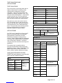
TABLE OF CONTENTS
PRINCIPLE OF OPERATION............................................ 4
COULOMETRIC METHOD ........................................ 4
INITIAL PREPARATIONS .............................................. 4
LINE VOLTAGE ................................................. 4
CLIP.......................................................... 4
RUBBER GASKET .............................................. 4
TEST CELL .................................................... 4
CLEANING PROCEDURE ......................................... 5
AGITATOR..................................................... 5
CLEANING THE TEST SPOT ...................................... 5
SUBSTRATES .................................................. 5
THICKNESS RANGE ............................................. 5
BALANCE KNOB ................................................ 6
CALIBRATION KEY.............................................. 6
CALIBRATION KNOB ............................................ 6
SENSITIVITY KNOB ............................................. 6
GO/NOGO KEY ................................................. 7
E/M KEY ...................................................... 7
SEL KEY ...................................................... 7
L/O KEY....................................................... 7
STORE KEY ................................................... 7
PRINT KEY .................................................... 7
ACCESSORY PORT ............................................. 7
NF6M MEASURING STAND ............................................ 8
EQUIPMENT REQUIRED ......................................... 8
PROCEDURE FOR TEST STAND SET-UP ........................... 8
SPECIMEN SET-UP ............................................. 9
DAILY CHECKLIST .................................................. 10
SET-UP CHECKLIST ................................................. 10
MAKING THE TEST .................................................. 10
CALIBRATION ...................................................... 11
PROGRAM MODULE DE-PLATING CURRENTS ........................... 11
CERTIFICATION ............................................... 11
KOCOUR THICKNESS STANDARDS .................................... 12

Page 2 of 21
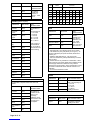
STOCK STANDARDS ........................................... 12
MULTILAYER STOCK STANDARDS ............................... 12
TEST SOLUTIONS AND APPLICATIONS ................................. 13
TEST SOLUTIONS ............................................. 13
APPLICATIONS ................................................ 13
TEST SOLUTION/APPLICATION CHART ............................ 13
BRASS ................................................. 13
CADMIUM ............................................... 13
CHROMATE ............................................. 13
CHROMIUM (+6) .......................................... 13
COBALT ................................................ 14
COPPER ................................................ 14
ELECTROLESS NICKEL PHOSPHOROUS ALLOY ............... 14
GOLD .................................................. 14
INDIUM ................................................. 14
IRON ................................................... 14
LEAD................................................... 15
LEAD-TIN 40/60 .......................................... 15
NICKEL-IRON ALLOY...................................... 15
NICKEL ................................................. 15
SILVER ................................................. 15
TIN .................................................... 15
TIN 95% SILVER 5% ...................................... 15
TIN-COBALT 80/20 ALLOY ................................. 16
TIN-NICKEL 65/35 ALLOY .................................. 16
TIN-ZINC 78/22 ALLOY .................................... 16
ZINC ................................................... 16
PROGRAM MODULES ............................................... 17
PROGRAM MODULE A FOR 0.136" DIAMETER TEST AREA ............ 17
PROGRAM MODULE B FOR 0.100" DIAMETER TEST AREA ............ 17
PROGRAM MODULE C FOR 0.063" DIAMETER TEST AREA ............ 17
PROGRAM MODULE D FOR 0.030" DIAMETER TEST AREA ............ 17
PROGRAM MODULES MA AND MB FOR THIN DEPOSITS............. 17
PROCEDURE FOR TESTING USING PROGRAM MODULE MA AND MB . . 17
SPECIAL APPLICATIONS AND ACCESSORIES ........................... 17
MULTIPLE LAYER COATINGS .................................... 17
ACCESSORIES ................................................ 18
WIRE TESTING .......................................... 18
STEP TEST.............................................. 18
PRINTER ............................................... 18
RS232 INTERFACE ....................................... 18

Page 3 of 21
MAINTENANCE ..................................................... 18
PROBLEMS AND SERVICING .................................... 18
TROUBLESHOOTING CHECKLIST ........................... 18
REPLACEMENT PARTS ......................................... 18
SERVICE & WARRANTY ............................................. 20
WARRANTY .................................................. 20
SERVICE ..................................................... 20
SERVICE RETURN INFORMATION ................................ 21

Page 4 of 21
PRINCIPLE OF OPERATION
COULOMETRIC METHOD
The Kocour 6000 Thickness Tester operates by
anodically de-plating a small area of the
specimen. The cell which holds the test solution
also serves as a cathode, and the article to be
tested is made the anode.
At the start of the test and until the substrate is
exposed, a voltage characteristic of the plating
exists across the cell. When all of the plating
has been removed from the test spot, this
voltage changes sharply and assumes a new
value characteristic of the substrate. This rapid
voltage change is the endpoint of the test, and is
amplified and used to operate a relay which
terminates the test.
The time required to dissolve the plating on the
test spot is proportional to the thickness of the
deposit. By correlating the area of the test spot
with the current used to strip the plating, the
counter is made to read directly in units of
thickness. Most coatings do not require
calculations or references to graphs or charts to
obtain thickness.
The test solutions used are specifically designed
to give 100% anodic current efficiency. They do
not attack the plating unless current is flowing
through the test cell. The anode efficiency is
further maintained by providing agitation of the
solution in the test cell.
The test spot is defined by means of a small
rubber gasket having an accurately dimensioned
perforation. The diameter of the test spots
available range from 0.030" (0.76 mm) to 0.136"
(3.4 mm) in diameter.
The coulometric method meets the requirements
of ASTM B504, ISO 2177, DIN 50932, DIN
50955 and BS5411-Part 4.
Please note that all references to chromium
deposits in this document refer to a deposit
plated from an hexavalent (+6) chromium
plating process.
INITIAL PREPARATIONS
To operate the instrument properly it is essential
that the operator be thoroughly familiar with the
material presented in this manual. Do not use
the instrument until you have read this material.
LINE VOLTAGE
The Kocour 6000 is a 120V/240V dual voltage
unit. The voltage is displayed on the voltage
selector/fuse holder that is located in the AC
receptacle on the back panel. The voltage input
can be changed by removing the fuse drawer
and turning the fuse holder until the desired line
voltage appears in the display window.
CLIP
The rubber insulated alligator clip attached to
the red lead wire MUST be kept clean. If the clip
becomes corroded, poor connection to the
samples may result in fluctuation of the
BALANCE meter indicator or may even cause a
premature endpoint. Open the jaws of the clip
and use an abrasive to remove rust and
corrosion.
RUBBER GASKET
The rubber gasket determines the exact area to
be tested. Handle it with care. Occasionally,
remove the rubber gasket from the cell and
examine it carefully. Do not allow any solid
material to accumulate. This might obstruct the
gasket hole. It is suggested that the gasket be
examined periodically under a magnifying glass
for possible deterioration.
TEST CELL
The test cell MUST be kept clean. Wipe bottom
of gasket with a damp absorbent tissue and
proceed with next test.
When tests are made, metal dissolved from the
specimen will be deposited on the inside of the
cell. An accumulation of such deposits may
interfere with tests and should be cleaned by the
method listed below. Remove the cell from the
cell holder by loosening the set screw in the rear
of the cell block holder. REMOVE THE
RUBBER GASKET BEFORE DIPPING THE
CELL IN ACID.
CLEANING PROCEDURE

Page 5 of 21
CAUTION: 20% HNO3 solution is corrosive.
Gloves, aprons and face shields are
recommended for safe handling.
The accumulated deposits from these coatings
may be removed by first rinsing thoroughly in
D.I. water. Then soak in a solution of 1 part
Nitric Acid (conc) and 4 parts D.I. water until you
are prepared to use it again. Then simply
remove cell from the solution with Stainless
Steel tongs or tweezers, rinse with tap water
and dry. The accumulated deposits may also be
partially removed by reaming the I.D. of the cell
with the cell cleaning brush.
AGITATOR
Agitation is required for many of the
coating/substrate combinations. Refer to the
Test Solutions/Application chart for instructions.
Agitation is provided by a calibrated pulsating air
column. The dimensions and position of the
agitator tube in the cell are important. For this
reason, it is imperative that the gasket and the
agitator tube assembly be matched. For
example: An "A" gasket must be used with the
"A" agitator tube assembly.
CLEANING THE TEST SPOT
The spot to be tested must be clean.
Fingerprints can interfere with the test; however,
they are easily removed by wiping with a solvent
such as alcohol or acetone. If the plated surface
is lacquered, remove the lacquer with a solvent
before cleaning the test spot. Chromate films on
zinc or cadmium deposits must be removed
prior to testing. The film may be removed by
LIGHTLY rubbing the test spot with a pencil
eraser. Chromate films on zinc or cadmium are
more precisely removed using an electro-
chemical method. This method requires
modification of the test stand. Call the Kocour
Company for information. Tin and nickel plated
samples may acquire a passive film on standing.
This film can be removed by placing 2 drops of
R-50 on the test area, rinse, then wipe dry
immediately and proceed with the test.
SUBSTRATES
The term SUBSTRATE as used in connection
with this instrument refers to the metal
immediately underneath the plating being tested;
not necessarily the metal from which the article
is fabricated. For example, consider a piece of
steel which has been copper plated, then nickel
plated and finally chromium plated. When
testing the chromium, the substrate is nickel;
when testing the nickel, the substrate is copper;
and when testing the copper, the substrate is
steel.
Where steel is referred to as a substrate, the
reference is generally to polished, cold-rolled
mild steel. Satisfactory tests have been made
with other types of steel as the substrate,
including stainless steels. In most cases where
the substrate is other than mild steel, it is
recommended that representative samples be
submitted to Kocour Company for evaluation.
These remarks also apply in any case where
steel or another substrate has been subjected to
any special processing (such as heat-treating)
which may result in a radical alteration of the
surface prior to plating. Difficulty may be
encountered in testing deposits over soft, gray
and cast iron.
THICKNESS RANGE
The minimum thickness of deposit which can be
tested with the basic instrument is 2-3 Fin for
chromium and gold and 20 - 30 Fin for other
metals. If deposits less than the minimum
thicknesses specified above are tested, the
endpoint will develop before the instrument can
detect it. In such cases, the instrument will
continue to run indefinitely. If this occurs, the
test should be stopped manually by depressing
the GO/NOGO key and the test spot examined.
If the deposit has been removed from the test
spot, its’ thickness is less than the specified
minimum.
The maximum thickness of chromium which can
be tested is approximately 2 mil. For gold, the
maximum thickness is 80 - 100 Fin. For other
metals, satisfactory results may be expected up
to approximately 1 - 2 mils depending upon the
type of plating and substrate. Generally, for
coatings greater than 1.0 mil, it is suggested to
stop the test, remove the cell solution, record the
test result and re-run the test adding the

Page 6 of 21
recorded test results. If deposits of appreciably
greater thickness are to be tested, it is
suggested that a representative plated sample
be submitted to Kocour Company for evaluation
and recommendations.
This instrument indicates essentially local
thickness. It is recommended that at least three
tests be made on significant surfaces to obtain a
better estimate of the average thickness.
BALANCE KNOB
Periodically, the Balance should be checked.
For proper operation of the instrument, the
Balance indicator should be centered on the
meter face. The Balance adjustment procedure
is outlined in the "Calibration" section.
During an actual thickness test, small
fluctuations of the Balance Meter indicator are
normal and may be disregarded.
Improper cleaning of the test spot, faulty
connection to the specimen, cell leakage, or air
bubbles on the test spot may cause the meter
indicator to fluctuate wildly during a test. DO
NOT TURN THE BALANCE ADJUSTMENT
KNOB DURING AN ACTUAL THICKNESS
TEST.
CALIBRATION KEY
This key is used to display the amperage during
the "Daily Check-List" and "Calibration". See
these sections for proper usage.
CALIBRATION KNOB
The Kocour Thickness Tester is equipped with a
calibration adjustment which will permit
correction of errors of approximately 10% in
either direction. Directions for calibrating the
instrument against Kocour Thickness Standards
are given under "Calibration" section; however,
the following general points should be noted:
1. If the 6000 has not been calibrated with
a Kocour Thickness Standard, the
amperage should be set to the value
assigned to that coating in the
"Calibration" section.
2. It is recommended to check the
instrument against a Thickness
Standard daily, at the beginning of each
working period or when the plating
application has changed. If doubtful
results are obtained subsequently, the
instrument should be re-checked
against the standard.
3. A check against a Kocour Thickness
Standard will provide a positive
indication as to whether or not the
instrument is functioning properly. If a
calibration is made as described, certain
general sources of error will be
compensated for. However, the
calibration figure obtained for a
particular plating-substrate combination
may not apply exactly to a different
combination. For example, if the
instrument is calibrated against nickel
on steel thickness standard the
calibration may not necessarily apply
exactly to silver on copper. It is
recommended to calibrate the
instrument against a standard
corresponding to the type of work being
tested. (see ASTM B504-90(1997,
Sub¶ 6.4) A variety of thickness
standards, listed elsewhere, are
available from Kocour Company.
SENSITIVITY KNOB
The normal (minimum) sensitivity position is full
counter-clockwise. The thickness test endpoint
is indicated by a large deflection of the
BALANCE METER indicator, at which time the
instrument will turn off. Certain plating-basis
metal combinations will at times give rise to
weak endpoints in which case the BALANCE
meter deflection will not be sufficient to turn the
instrument off. In such cases increase the
sensitivity by turning the SENSITIVITY knob
clockwise 1/8 to 1/4 turn and repeat the test.
Repeat this procedure until proper end point
occurs. This will be your setting until plating-
basis metal combinations change. In general all
tests should be made with the sensitivity at the
normal (minimum) standard setting, and the
sensitivity should be increased only when
required as noted above. DO NOT ADJUST
SENSITIVITY DURING AN ACTUAL

Page 7 of 21
THICKNESS TEST; TEST WILL TERMINATE.
E/M KEY
The E/M key permits the choice of English units
(mils) or Metric units (micrometers). This choice
has to be made prior to testing. The key cannot
be used to perform units conversion after the
test is made.
GO/NOGO KEY
This key is used to start the test after the sample
has been set-up according to the instructions in
the "Specimen Set-Up" section. Pressing the
GO/NOGO key automatically removes existing
data from the display and starts the test. This
key also terminates the test. When the
GO/NOGO key is engaged, the green LED on
the key will light.
SEL KEY
The coating selector key is used to access the
proper amperage for testing that coating. The
list below is a reference for the coating to the
chemical symbol on the key.
KEY COATING KEY COATING
Au GOLD Zn ZINC
Cr2DECORATIVE
CHROMIUM(+6)
Brs BRASS
Ag SILVER Cu COPPER
Sn TIN Ni NICKEL
Cd CADMIUM Cr1INDUSTRIAL
CHROMIUM(+6)
L/O KEY
This key is used to lockout the Automatic
Termination Circuit. When this key is engaged,
an "LO" will appear on the lefthand side of the
display. This feature is used in conjunction with
the "STEP TEST".
STORE KEY
This key is used to send the display readings to
the memory.
PRINT KEY
This key is used to send the contents of the
memory to the printer.
ACCESSORY PORT
The Accessory Port is located on the front panel
in the lower left-hand corner. It is used to
connect the various measuring stands and WT
accessory.

Page 8 of 21
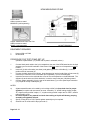
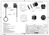
NF6M MEASURING STAND
Contact block
w/direct contact to stand.
#36026CB (sold separately)
Copper Jawed Small Parts Test Vise
w/direct contact to stand.
#36050 (sold separately) LAYOUT DRAWING
EQUIPMENT REQUIRED
1. Kocour 6000 or K 5000
2. NF6M Stand
PROCEDURE FOR TEST STAND SET-UP
(Numbers in parentheses “(4 )” below refer to parts in schematic, above.)
1. Connect black patch cable to the 9 pin receptacle at the rear of the NF6M stand and to the 9 pin
accessory port on the left hand side of the Kocour 6000 front panel or cell receptacle on rear of
K-5000.
2. Insert cell (4) with cell washer (not shown) and gasket (5) into the cell holder (3). Lock into
position with cell set screw (6).
3. Connect the black lead wire as follows: Insert banana plug into the head of the cell set screw (6).
Insert the pin connector to one of the black pin receptacles (11) on the NF6M stand.
4. Insert the connector on the red lead wire to one of the red receptacles on the NF6M stand. The
alligator clip at the other end of this lead wire is used to connect the part (14b) being tested.
5. Connect agitator assembly (2) to the rear of the stand base (7) or to the optional port extension
(15) coupler at the top of stand post (8).
NOTES:
a) Agitator assemblies are color coded by color tubing w/relief hole (keep hole clear for proper
agitation) in coupler and must remain as a set. Assembly ”A”, w/clear tubing w/relief coupler;
“B”, w/green tubing w/relief coupler; “C”, w/yellow tubing w/relief coupler and “A STEP”, w/white
tubing w/relief coupler.
b) Do not let liquids or any material run back down tubing as liquids will destroy pumping
assembly and agitation will quit.
c) Specify if using R-48 or R-52, special agitator assembly may be required.
d) Solution level in cell should be kept just under ½.

Page 9 of 21
SPECIMEN SET-UP (see NF6M drawing above)
1. Set the test sample at position (14a) under the Height set slider gauge (10).
2. Lower the Height set slider gauge (10) until it touches the test area on the sample. Lock the
Height gauge in this position.
3. Carefully lift the Cell Holder (3) and slide the test sample from position (14a) to position (14b)
under the gasket (5). Center the gasket on the test area. The steps 1 - 3 assure that the
pressure on the gasket is proper for testing.
4. A liquid barrier may form in the agitator head assembly and must be removed prior to use. This
is accomplished by tapping the grey tip to release this barrier.
Note: When using standard or part under 1" thick, set standard or part up on a 1" block before
bringing height set slider block (10) down for positioning. When a test part (14) is too tall
or too large for a proper set-up on base (7), place the test part behind the stand, swing the
height set slider (10) around facing the part and continue with step 2 above. If additional
room is required, an optional bumper block assembly can be purchased.
DO NOT ALTER ANY PART OF AGITATION SYSTEM AS TEST RESULTS WILL BE INVALID!

Page 10 of 21
DAILY CHECKLIST
1. Press the toggle switch located in the AC receptacle on the rear panel to the "ON" position. The
red power indicator on the front panel will light at this point.
2. Press the "SEL" key until the desired coating appears on the extreme left side of the display.
3. Insert terminals on yellow shorting cable into red and black jacks in the front of measuring stand.
4. Press "GO/NOGO". *
5. Center the indicator on the balance meter with the balance knob. *
6. Find the recommended current for your coating/module combination in the list on page 11. Then
press and hold the "CAL" key while you adjust the cell current to that value. Hold the "CAL" key
for 3-5 seconds after the adjustment to guarantee that the current has stabilized, then release
key.
7. Remove yellow shorting cable. Termination should occur.
Note: If the end-point does not occur at this point, refer to the "Problems and Servicing" section.
* If the 6000 shuts off before or when adjusting the balance.....
a. Press the "L/O" key. "LO" will appear in the center of the display.
b. Press "GO/NOGO".
c. Center the indicator on the balance meter with the balance knob.
d. Press "GO/NOGO".
e. Press "L/O". "LO" will be removed from display.
f. Return to step 4 and continue with "Daily Checklist".
SET-UP CHECKLIST
1. Perform DAILY CHECKLIST.
2. Set calibration to the listed amperage or to the adjusted amperage obtained as the result of the
calibration procedure. (see Calibration, page 11)
3. Select Units - Press "E/M" key until the desired unit appears on right-hand side of the display.
4. Set "SENSITIVITY" to full counter-clockwise position, or to a position determined during the
calibration procedure. (see Calibration, page 11)
5. Choose the agitator that matches the gasket; i.e., the "A" gasket requires the "A" agitator tube
assembly and the "A" module.
MAKING THE TEST
1. Position specimen according to measuring stand instructions.
2. Fill the cell approximately ½ full with the PROPER test solution as determined from the Test
Solution/Application Chart. Make certain that no air bubbles remain attached to the test spot. To
avoid this, it is helpful to insert the "fill bottle" carefully into the cell until the tip touches the test
spot and then gently squeeze the bottle to expel the solution from the "fill bottle" to the desired
volume in the cell.
3. Insert agitator assembly (2) into Cell Holder (3). NOTE: Some tests do not require agitation.
Refer to the Test Solution/Application Chart starting on page 13.
4. Press the "GO/NOGO" key firmly to start the test. When the test is complete the instrument will
shut off automatically and the thickness will appear on the display.
5. Carefully remove the agitator assembly (2) from Cell Holder (3).
6. Use the wash bottle labeled "WASTE" as a suction device to remove and store spent test
solution.
7. Remove test specimen.
8. Wipe the bottom of the gasket with a damp absorbent tissue. The cell is ready for additional
testing. If deposits remain in cell, use the cell cleaning brush supplied with the NF6M measuring
stand.

Page 11 of 21
CALIBRATION
1. For best results, the 6000 should be calibrated at the beginning of a work period and when:
a) the gasket is changed
b) changing the coating being tested
2. Use a Kocour thickness standard with the same coating/substrate combination as the sample to
be tested.
3. Make at least three random tests on this standard and calculate the average of these tests. If
this average agrees with the value on the face of the standard, the unit is calibrated.
4. If this average disagrees with the value on the face of the standard, use the formula below to
calculate the new cell current.
CALIBRATION SETTING = CURRENT x (AVERAGE (of three tests) ÷ THICKNESS)
EXAMPLE CALCULATION: CALIBRATION SETTING = 34.9 x (0.497 ÷ 0.51) = 34.0
where:
THICKNESS on standard = 0.51 mil
AVERAGE of three tests = 0.497
CURRENT used for tests = 34.9 ma
CALIBRATION setting = 34.0 ma
5. Use steps 2-7 in "Daily Checklist" to set cell current to the calibration setting and the Kocour 6000
is re-calibrated. The calibration should be verified by re-testing the standard.
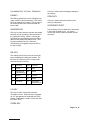
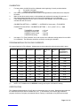
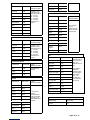
PROGRAM MODULE DE-PLATING CURRENTS
All currents listed are in DC milliamps. Adjustments must be made with yellow shorting cable in place.
COATING MODULE A MODULE B MODULE C MODULE
MA
MODULE
MB
D STAND
ACCESSORY
MODULES (1)
Cr1 (+6) 46.0 23.0 9.67 0 0 2.25
Ni 34.9 17.5 7.55 3.49 1.76 1.90
Cu 32.2 16.0 6.80 3.22 1.61 1.685
Brs 30.0 15.0 6.27 3.00 1.49 1.63
Zn 24.2 11.8 4.99 2.51 1.25 1.24
Cd 17.6 8.8 3.55 1.76 0.87 0.87
Sn 14.0 7.0 2.79 1.40 0.69 0.68
Ag 11.2 5.6 2.66 1.12 0.55 0.53
Cr2 (+6) 10.2 4.5 1.97 0 0 0.49
Au 2.67 1.4 0.61 0 0 0.156
(1) NOTE: All “D” Modules are for SPECIFIC coatings and require a D-Stand for testing.
CERTIFICATION
The Calibration Method above will verify that your instrument set-up is correct. Measurements made with
the calibrated instrument will be traceable to N.I.S.T. In the absence of an internal gage calibration
program, the Kocour Company recommends Kocour Factory re-certification to be performed annually.

Page 12 of 21
KOCOUR THICKNESS STANDARDS
KOCOUR Thickness Standards are intended to
be used as a periodic check on the operation of
the KOCOUR 6000 Thickness Tester and to
calibrate the instrument (see Calibration
section).
KOCOUR Thickness Standards cannot be given
a protective coating because of the manner in
which they are used. Therefore, standards are
subject to corrosion as are all metals. For this
reason and because of variations in handling
and storage in the field, no definite useful life
can be specified. KOCOUR Thickness
Standards will retain their usefulness for a
maximum period, if the following precautions are
observed:
1. Always store standards in the plastic re-
usable box or bag provided.
2. DO NOT clean the standards with
abrasives, acids or other strong
chemicals.
3. After use, the thickness standard should
be rinsed with water, dried immediately
and replaced in the container. DO NOT
store wet standard in container.
4. Avoid touching the standard with your
fingers.
Before making a test on a standard, wipe the
standard gently with facial tissue soaked with
acetone or alcohol.
Choose your standards from the "Stock
Standards" list. These standards are adequate
to calibrate the Kocour 6000 for most common
plating thickness ranges. If the coating you are
testing is thinner than 0.05 mil (1.3 microns) or
thicker than 1.0 mil (25 microns), contact Kocour
Company at (773) 847-1111 for
recommendations.
The Kocour Company manufactures a complete
line of calibration standards. A brochure with
descriptions and prices is available.
Please note that all chromium plating of
Kocour Standards is from an hexavalent (+6)
chromium process. All references to
chromium within this document refer to
hexavalent (+6) chromium plating.
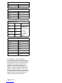
STOCK STANDARDS
PLATING/ NOMINAL
SUBSTRATE THICKNESS
Cadmium/brass 500 Fin (12.7 Fm)
Cadmium/copper 500 Fin (12.7 Fm)
Cadmium/steel 500 Fin (12.7 Fm)
Chromium/brass 200 Fin (5.0 Fm)
Chromium/copper 200 Fin (5.0 Fm)
Chromium/nickel 20 Fin (0.5 Fm)**
Chromium/steel 200 Fin (5.0 Fm)
Copper/steel 500 Fin (12.7 Fm)
Copper/zinc 250 Fin (6.2 Fm)
Gold/brass 25 Fin (0.6 Fm)**
Gold/copper 25 Fin (0.6 Fm)**
Gold/nickel 25 Fin (0.6 Fm)**
Nickel/brass 500 Fin (12.7 Fm)
Nickel/copper 500 Fin (12.7 Fm)
Nickel/steel 500 Fin (12.7 Fm)
EN/steel 200 Fin (5.0 Fm)
Silver/brass 500 Fin (12.7 Fm)
Silver/copper 500 Fin (12.7 Fm)
Silver/steel 500 Fin (12.7 Fm)
"STEP"/copper 600 Fin (15.0 Fm)
"STEP"/steel 500 Fin (15.0 Fm)
Tin/copper* 500 Fin (12.7 Fm)
Tin/brass * 500 Fin (12.7 Fm)
Tin/steel 500 Fin (12.7 Fm)
Tin/steel 30 Fin (0.8 Fm)**
Zinc/brass 500 Fin (12.7 Fm)
Zinc/copper 500 Fin (12.7 Fm)
Zinc/steel 500 Fin (12.7 Fm)
Thicknesses listed above are nominal
* These standards are made to order, due to the
formation of a copper-tin inter-metallic layer that
interferes with the calibration.
** Example: 20 Fin = 0.000020" = 0.20 mil
MULTILAYER STOCK STANDARDS
Chromium/Nickel/Copper on Zinc
Chromium/Nickel/Copper on Steel
Chromium/Nickel on Copper
Chromium/Nickel on Steel
Thicknesses for above: Cr: 0.02mil (0.5 Fm)
Ni: 0.6mil (15.0 Fm)
Cu: 0.2mil (5.0 Fm)

Page 13 of 21
TEST SOLUTIONS AND
APPLICATIONS
TEST SOLUTIONS
The test solutions are generally stable and not
subject to deterioration on standing unless
contaminated or subjected to excessive
evaporation. Some of the test solutions may
crystallize on standing, especially if cold. This
does not indicate decomposition. Avoid transfer
of solid to the test cell. Pour from bottle into
beaker and warm slightly, then transfer solution
back into bottle and mix until crystals dissolve.
After each test, remove the solution from the
cell. Test solutions can be used one time only.
Flush the cell with water, then wipe the bottom
of the gasket with a piece of damp absorbent
tissue. This procedure removes loose particles
that may interfere with the next test and
prepares the gasket for proper sealing.
APPLICATIONS
The TEST SOLUTION/APPLICATION CHART
lists the correct test solution for a particular
plating/substrate combination and other
instructions necessary for making the test
properly. Where a plating/substrate combination
is not listed, this indicates that the combination
may not have been evaluated. The Kocour
Company should be consulted concerning such
applications.
Test solutions are not supplied with the
instrument and should be ordered as specific
applications require. Order a 250ml Dispensing
bottle of each solution initially, and 250ml,
500ml, 1000ml or gallon quantities as needed.
TEST SOLUTION/APPLICATION
CHART (All require agitation, unless otherwise
stated: “DO NOT USE AGITATION”)
BRASS(1)
SUBSTRATE SOLUTION TEST
INSTRUCTIONS
Aluminum R-44 (1) see
“ACCURACY...
ALLOY
COATINGS
Non-metallics R-44
Steel R-44
Copper R-44H
CADMIUM (Agitation required, unless otherwise specified)
SUBSTRATE SOLUTION
Aluminum R-45
Brass R-45
Copper R-45
Nickel R-45
Non-metallics R-45
Steel R-45
Tungsten R-45
CHROMATE
R-2 removes the chromate without attacking the cadmium or
zinc. The displayed reading is not a thickness measurement.
SUBSTRATE SOLUTION TEST INSTRUCTIONS
Cadmium R-2 Refer to Chromate strip
procedure, available upon
request.
Zinc R-2
CHROMIUM (+6)
Use Cr2setting for 2-80u-in. Use Cr1setting for 90u-in and
above.
SUBSTRATE SOLUTION TEST INSTRUCTIONS
Aluminum R-51 AGITATION FOR R-51
(CHROMIUM) OPTIONAL
Brass R-47
Cobalt R-47
Copper R-47
Nickel R-51
Nickel-silver R-47
Non-metallics R-51
Stainless Steel R-51
Steel R-51
Zinc Die Cast R-58 For Chromium(+6t) direct
on Zinc Die Cast
Inconel R-51 AGITATION FOR R-51
(CHROMIUM) OPTIONAL
Nickel-Iron
Alloy
R-51
Inconel '600' R-51
304 Stainless
Steel
R-51
Cadmium R-47

Page 14 of 21
COBALT
SUBSTRATE SOLUTION TEST
INSTRUCTIONS
Brass R-54 For testing
Cobalt, set
selector at
Nickel ... reads
direct
Copper R-54
Steel R-54
COPPER (Agitation required)
SUBSTRATE SOLUTION TEST
INSTRUCTIONS
Aluminum R-44 * Set selector to
“Cd”
Set amperage at:
A - 16.10 mA
B - 8.05 mA
C - 3.40 mA
MA - 1.61 mA
MB - 0.81 mA
MC - 0.35 mA
Note: Copper on
steel standards
can or should be
used with all R-44
solution testing
Aluminum-
bronze
R-44
Beryllium-
copper
R-52*
Brass R-52*
Iron-Nickel
alloy
R-44
Kovar R-44
Lead R-52*
Molybdenum R-44
Nickel R-44
Non-metallics R-44
Steel R-44
Tungsten R-44 R-44
Uranium R-44
Zinc Die Cast R-52*
Cadmium R-52*
Silver R-44
ELECTROLESS NICKEL PHOSPHOROUS ALLOY (1)
Not applicable to deposits which have been heat
treated.
SUBSTRATE SOLUTION TEST
INSTRUCTIONS
Aluminum R-57 Set selector as
indicated in next
column. Set
amperage
(milliamps) to the
value listed for that
Phosphorous %.
Use agitator.
Kovar R-57
Non-metallics R-57
Steel R-57
Silicon R-57
Mag. Stainless
Steel
R-57
Copper R-1
Sel. Set Nickel Chromium
Thk. = Direct Display X 2
% Phos. 4% 5% 6% 7% 8% 9% 10% 11% 12%
A amp. 38.7 39.8 40.5 41.5 42.6 43.3 44.0 44.7 45.4
B amp. 19.4 20.0 20.3 20.8 21.4 21.7 22.1 22.4 22.8
C amp. 8.4 8.6 8.8 9.0 9.2 9.4 9.5 9.7 9.8
D amp. 2.11 2.17 2.20 2.26 2.32 2.36 2.39 2.43 2.47
GOLD
SUBSTRATE SOLUTION TEST
INSTRUCTIONS
Brass R-56 All tests ...
readings are in
micro-inches
(millionths of an
inch). Make
certain cell is
clean and rinsed
after each test.
Copper R-56
Electroless Nickel R-56
Nickel R-56
NOTES:
1. Rub lightly with a non-abrasive eraser prior to testing.
2. Test is based on pure gold (density of 19.3 g/cm3). To
convert to milligrams per square centimeter, divide micro-
inches by 20.
3. Maximum Gold thickness 80 - 100 micro-inches.
4. Not recommended for gold deposited directly over steel,
Kovar or Silver.
5. Solution R-56 is very sensitive to contamination. When
testing Gold, the cell, rubber gasket and the agitator should
be thoroughly cleaned and rinsed free of any solution
remaining from previous tests. When contamination occurs,
the Gold is not dissolved and the test will continue to run
indefinitely.
6. Do not use M” Modules for Gold.
INDIUM
SUBSTRATE SOLUTION TEST INSTRUCTIONS
Steel R-59 All tests ... set selector at
ZINC. Set amperage at:
A - 22.0 mA
B - 10.7 mA
C - 4.54 mA
D - 0.94 mA
Readings are direct
Copper R-59
Brass R-59
Nickel R-59
IRON
SUBSTRATE SOLUTION TEST INSTRUCTIONS
Copper R-51 Set selector at Copper.
Readings are direct.

Page 15 of 21
LEAD
SUBSTRATE SOLUTION TEST
INSTRUCTIONS
Aluminum R-55 All tests ... set
selector at TIN.
Set amperage at:
A -12.7 mA
B - 6.35 mA
C - 2.54 mA
D - 0.62 mA
Readings are
direct
Brass R-55
Copper R-55
Kovar R-55
Non-metallics R-55
Silver R-55
Steel R-55
Tin R-55
Nickel R-55
LEAD-TIN 40/60(1)
SUBSTRATE SOLUTION TEST
INSTRUCTIONS
Aluminum R-49 All tests ... set
selector at TIN.
Set amperage at:
A -13.7 mA
B - 6.86 mA
C - 2.74 mA
D - 0.67 mA
Readings are
direct
Brass R-49
Copper R-49
Non-metallics R-49
Steel R-49
NICKEL-IRON ALLOY(1)
SUBSTRATE SOLUTION TEST
INSTRUCTIONS
Steel R-54 Set selector at
Nickel
Copper R-54
Brass R-54
NICKEL
SUBSTRATE SOLUTION TEST
INSTRUCTIONS
Aluminum R-54
* For Copper,
ASTM
specification B-
355 for wire with
accessory WT.
Set SENSITIVITY
at MAX.
Brass R-54
Copper R-54*
Inconel R-54
Kovar R-54
Molybdenum R-54
Nickel-silver R-54
Non-metallics R-54
Steel R-54
Tungsten R-54
Uranium R-54
Silver R-54
Chromium R-54
SILVER
SUBSTRATE SOLUTION TEST
INSTRUCTIONS
Aluminum R-44
+ For use with
test cell
* ASTM spec. B-
298 for wire with
Accessory WT
Brass R-48
Copper R-48; 1.5+
Copper R-48*
Nickel R-48
Nickel-silver R-48
Non-metallics R-44
Steel R-44
Tin R-48
Copper-
tungsten
R-48
Silver-tungsten R-48
TIN
Aluminum R-51 — Using
accessory WT for
Wire and small
parts only.
Measure free Tin
only
! No agitation.
Thickness
includes copper
from tin/copper
inter-metallic
layer. Tin
checked with
R-47 measures
free tin only.
Brass R-47
Brass wire R-50—
Cadmium R-47
Copper R-47
Copper wire>32G R-50—
Nickel R-47
Nickel-silver R-4
Non-metallics R-47
Steel R-47
Copper R-50!
Copper wire<32G R-R-50—
TIN 95% SILVER 5%
SUBSTRATE SOLUTION
Copper R-1

Page 16 of 21
TIN-COBALT 80/20 ALLOY
SUBSTRATE SOLUTION
Nickel R-2
TIN-NICKEL 65/35 ALLOY
SUBSTRATE SOLUTION
Steel R-2
Nickel R-2
Copper R-3
TIN-ZINC 78/22 ALLOY(1)
SUBSTRATE SOLUTION TEST
INSTRUCTIONS
Brass R-47 All tests ... set
selector at TIN.
Set amperage at:
A -16.8 mA
B - 8.4 mA
C - 3.35 mA
D - 0.82 mA
Readings are
direct
Copper R-47
Non-metallics R-47
Steel R-47
ZINC
SUBSTRATE SOLUTION
Aluminum R-46
Brass R-46
Copper R-46
Nickel R-46
Non-metallics R-46
Steel R-46
Tin R-46
(1) ACCURACY....ALLOY COATINGS
The Kocour Thickness Tester has been used to
test alloy coatings such as tin-lead (solder), tin-
zinc and brass, however, the accuracy of such
tests depends upon the composition of the
deposit which may vary with the process
variables. Certain alloy coatings may tend to
migrate or diffuse into certain substrates, thus
introducing another complication. The usual
degree of accuracy therefore, is not claimed for
the measurement of alloy coating thickness and
when the required accuracy is critical, other
appropriate methods should be used.

Page 17 of 21
PROGRAM MODULES
PROGRAM MODULE A FOR 0.136"
DIAMETER TEST AREA
While the Program Module "A" is adequate in
many thickness operations, the 6000 is provided
with the capability to determine coating
thickness within various ranges by inserting
program modules specific to each range.
The program modules will fit snugly into the
opening at the lower right of front panel. A
minimum amount of force is necessary for
insertion and removal.
NOTE: Do not insert or remove program
modules while GO/NOGO indicator is
illuminated when testing.
PROGRAM MODULE B FOR 0.100"
DIAMETER TEST AREA
Program Module B provides a means for testing
smaller areas, smaller parts, curved surfaces
and recessed ledged areas which are either not
accessible or do not offer a sufficient area to
accommodate the instruments standard gasket
A. This Module is supplied with the special Test
Cell B, Gasket B and B agitator assembly.
PROGRAM MODULE C FOR 0.063"
DIAMETER TEST AREA
Program Module C provides a means for testing
very small areas which are not accessible to
either the standard and the Gasket A or optional
Gasket B. The test procedure for C is identical
to that of Module B with one exception, Test Cell
B is used with Gasket C and the C agitator
assembly.
PROGRAM MODULE D FOR 0.030"
DIAMETER TEST AREA
Program Modules D-Cr1 thru D-Au are used for
specific coatings when using the "D" stand and
"D" agitator assembly. These modules provide
the correct cell current for each coating.
PROGRAM MODULES MA AND MB
FOR THIN DEPOSITS
Program Modules MA, MB & MC are intended
for testing deposit thickness in the general range
of 5 F-in (0.012 Fm) to 0.1mil (2.5 Fm). If the
deposit thickness is more than 0.1mil (2.5 Fm),
use the Module A, B or C. The MINIMUM
THICKNESS to be tested with the Program Module
MA, MB & MC is 3 F-in (0.075 Fm). Program Module
MA should be used only with Test Cell A. Do not use
for Gold or heavy Chrome.
PROCEDURE FOR TESTING USING
PROGRAM MODULE MA AND MB
1. Insert Program Module.
2. Select appropriate coating.
3. Procedures for making tests are the same as
with the Program Module A, B & C except
that the AGITATOR SHOULD NOT BE USED.
4. When using Module MA or MB all displayed
readings should be divided by 10 to give
correct figure.
5. If the balance indicator deflects but the Kocour
6000 does not terminate the test, increase the
SENSITIVITY control. (see page 6,
SENSITIVITY KNOB)
SPECIAL APPLICATIONS AND
ACCESSORIES
MULTIPLE LAYER COATINGS
The Kocour 6000 permits testing of all the layers of a
Multiple Layer Coating. A general procedure is listed
below. A list of procedures for specific multiple layer
coating combination follows the general procedure.
CAUTION: Take care that the specimen is properly
positioned before starting the test. Be very careful that
the cell and specimen are not moved during the filling,
solution removal and rinsing of the cell.
1. For greatest accuracy, calibrate the Kocour
6000 for every coating layer to be tested.
(record calibrated amperage)
2. Set-up specimen. See SPECIMEN SET-UP,
page 9.
3. Remove red pin connector on red cable from
red receptacle in front of NF6 stand. Take the
yellow jumper cable and insert one pin
connector in the red receptacle and the other
into the black receptacle in the front of the NF6
stand.
4. Select coating for the first layer to be tested.
5. Press "GO/NOGO".
6. Press and hold the "CAL" key while you adjust
the cell current to the value determined in step
# 1. Hold the "CAL" key for 3-5 seconds after
the adjustment to guarantee that the current
has stabilized.
7. Remove yellow jumper cable and replace the
red pin connector into the red receptacle.
8. Test the coating using steps 2 through 6 of
"Making the Test".

Page 18 of 21
9. Rinse cell 3 times without moving the
cell or specimen. Use the following
rinse procedure:
a) Aim the flow from a wash bottle
at the test area in the bottom of
the cell.
b) Remove rinse water by using
the "WASTE" bottle.
c) Repeat 9a and 9b two more
times for a total of three rinses.
10. Repeat steps 3 through 9 for the 2nd
layer.
11. If a 3rd layer is to be tested, repeat steps
3 through 9.
ACCESSORIES (purchased separately):
WIRE TESTING (supplied when purchased)
STEP TEST (supplied when purchased)
PRINTER (supplied when purchased)
RS232 INTERFACE (supplied when
purchased)
MAINTENANCE
PROBLEMS AND SERVICING
Most problems can usually be remedied by
comparing test conditions against the Checklist
provided below. If however, a problem persists
after going over the entire check list below,
factory service may be required.
1. Pack the instrument well and ship
Freight Prepaid.
2. FOR FACTORY SERVICE SHIP TO:
SERVICE DEPT.
KOCOUR COMPANY
4800 S. St. Louis Avenue
Chicago, Illinois 60632 (USA)
Phone: 773-847-1111
Fax: 773-847-3399
TROUBLESHOOTING CHECKLIST
BE SURE THAT THE....
1. Instrument is connected to the line
voltage specified on the name plate.
2. Balance indicator is centered between
black index lines.
3. Sensitivity is set full counter clockwise.
If meter deflects at or near expected
thickness but test does not terminate,
increase sensitivity.
4. Calibration knob has not been disturbed.
Re-adjust cell current to initial setting.
5. Specimen is clean.
6. Proper test solution is used.
7. Gasket, module and agitator assembly match;
that is, "B" gasket must be used with "B"
module and "B" agitator assembly.
8. Coating thickness is in the range of
application.
9. Selector is set to the proper coating.
10. Coating/substrate combination is applicable.
11. Specimen is set-up to insure proper
placement.
12. Test cell is clean.
13. Cell connector screw is clean & dry.
14. Gasket is clean & dry.
15. Cell washer is in place in the cell block.
16. Red lead wire is attached to specimen.
17. Clip is clean and free of corrosion.
18. Chromate films are properly removed prior to
testing. (see Test Solution/Application Chart)
19. Agitator is necessary for your application.
20. Proper solution level in cell and no air bubbles.
21. Air relief hole for agitation is clear.
22. Remove liquid barrier in agitator tip.
REPLACEMENT PARTS
370T04 Rubber Gasket "A" (package of 5)
370T05 Rubber Gasket "B" (package of 5)
370T12 Vinyl Cover
370T13 Black Cell Connector Screw Lead
370T15 Stainless Steel Beaker WT
COL0001 Rubber Collar WT
370T17 Neoprene Cell Washer
370T20 Operation Manual
370T21 Rubber Gasket "C" (package of 5)
370T22 Vinyl Gasket "D" (package of 5)
MFG0004 Test Cell "A" Stainless Steel
MFG0005 Test Cell "B" Stainless Steel
370T33 "A" Agitator Assembly for NF6
370T34 "B" Agitator Assembly for NF6
370T35 "C" Agitator Assembly for NF6
370T36 "D" Agitator Assembly
370T38 "A" Agitator Assembly for STEP
370T41 Fuse 1.2 Amp Slo-Blo (package of 5)
370T43 STEP Stand replacement electrode Kit
370T45 Test Cell "D" Stainless Steel
STP0002 Cell Holder Block
CAB6000 RS-232 Patch Cable
BRU0001 A cell cleaning brush
BRU0003 B cell cleaning brush
BOT0126 Wash bottle, 126 ml
370P00111 Strip Recorder Charts(package of 6)
370P0107 Strip Recorder Pens (package of 6)

Page 19 of 21
Contact Kocour Company at (773)847-1111 for
the following procedures:
A. Chromate Strip Procedure
B. Copper Plating on Brass Substrate
C. Test Tin and Copper Thickness after
inter-metallic layer has formed (over 40
F-in) (1 Fm)
D. Test Tin and Copper Thickness after
inter-metallic layer has formed (under 40
F-in) (1 Fm)
E. Cell voltage monitor assembly
instructions
F. Tin pounds/base box
G. "D" Stand Instructions
H. "STEP" Stand Instructions
I. Immersion Tin on Aluminum
J. Wire Test Accessory Instructions
K. RS232 interface
L. SPC printer-processor
M. Special application stands
N. Small parts test vise
O. Contact Block
Page is loading ...
Page is loading ...
-
 1
1
-
 2
2
-
 3
3
-
 4
4
-
 5
5
-
 6
6
-
 7
7
-
 8
8
-
 9
9
-
 10
10
-
 11
11
-
 12
12
-
 13
13
-
 14
14
-
 15
15
-
 16
16
-
 17
17
-
 18
18
-
 19
19
-
 20
20
-
 21
21
-
 22
22


Ask a question and I''ll find the answer in the document
Finding information in a document is now easier with AI
Other documents
-
 Hach DR/700 Procedures Manual
-
 Conec 17-101814 Operating instructions
-
SRS QCM200 Owner's manual
-
Lamotte 2000-02-MN Instructions Manual
-
 Kett LZ-373 Operating instructions
-
Elpidan Coating Thickness Gauge User guide
-
Lincoln Electric KH513 Installation guide
-
-
Duracell 9V MN1604 Alkaline Battery Box User guide
-
 Hach DR2400 User manual


