Page is loading ...

Installation &
Operation Manual
Rev. 1/2019
Willoughby Industries, Inc.
5105 West 78th Street
Indianapolis, IN 46268
Toll Free: (800) 428-4065
Local: (317) 875-0830
Fax: (317) 875-0837
www.willoughby-ind.com MADE IN THE U.S.A.
Table of Contents
Pre-Installation Information �������������������������������������2
Physical / Rough-in Dimensions �����������������������������3
Required Installation Supplies ��������������������������������4
Parts List ����������������������������������������������������������������5
Hardware Identication ������������������������������������������6
Installation Instructions ���������������������������������������������
Step 1: Pedestal Mounting ���������������������������������7
Step 2: Drain Assembly �������������������������������������8
Step 3: Head and Basin Assembly ��������������������9
*WWF-4203/4204-PSL-FT
Assembly Drawing �����������������������������10
Step 4: Connections for Pneumatic Foot
Control Actuators ��������������������������������� 11
Step 5: Final Assembly ������������������������������������12
JACO Fitting Instruction ����������������������������������������13
Adjustable Mixing Valve Installation ���������������������14
Self-Closing Pneumatic Valve ����������������������������������
Operation Details ���������������������������������������������� 15
Operation and Maintenance �����������������������������16
Liquid Soap Specication and Maintenance ���������17
Care and Maintenance �����������������������������������������18
Troubleshooting ��������������������������������������������������������
Self-closing Pneumatic Valves ��������������������������19
Drawings �������������������������������������������������������������������
General Dimensions and Rough-in Detail ��������21
Valve Details �����������������������������������������������������22
Miscellaneous Details ��������������������������������������� 25
Warranty ��������������������������������������������������������������� 28
WWF-4203-PSL-FT Series
WWF-4204-PSL-FT Series
Three- or Four-station 42" 180°
Stainless Steel Washfountain
Pneumatic Foot Control
WWF-4204-PSL-FT

Installation & Operation Manual
Stainless Steel 180° Washfountain
WWF-4203-PSL-FT / WWF-4204-PSL-FT
Willoughby Industries, Inc. TOLL FREE (800) 428-4065 ● LOCAL (317) 875-0830 ● FAX (317) 875-0837
Page 2Rev. 1/2019 www.willoughby-ind.com
Pre-Installation Information
When installing the Willoughby Industries' WWF-4203/4204 Series washfountain system:
Before Step 1 of the installation instructions, ensure that rough-ins are in the correct location�
The valve assembly, including the spray head, MUST NOT BE connected until after
all lines have been ushed to remove the small particles of debris that are inherent
with new construction projects and all chemicals that are used in ushing are purged
from the system�
Chemicals used in ushing plumbing systems can attack the internal components of
the valve and spray head and severely damage them, so any ushing of the system
must be followed by a full ushing with pure water to clear any harsh chemicals
remaining in the system� Debris in the system if allowed to enter the valve assembly
and spray head can cause poor performance or outright failure�
Again DO NOT attempt to connect the valve assembly and spray head until after all
ushing is complete and pure water is the only media that will be passing through the
system� Damage to the valve assembly or spray head caused by harsh chemicals or
debris will not be covered by the manufacturer's warranty�
INSTALLATION INSTRUCTIONS
Visit our website at http.//www.willoughby-ind.com
2210 West Morris Street • P.O. Box 21217 • Indianapolis, IN 46221
(317) 638-2381 • Fax: (317) 638-6110 • (800) 428-4065
© Rev. 11/2007 Page 3
Installation notice!
Check Rough-in location and flush lines prior to hook up!
When installing the Willoughby Industries’ WAW, WAF, or WWF series
washfountains or lavatory deck systems:
Before Step 1 of the installation instructions, ensure that rough-ins are in the correct
location.
It is essential that the water supply lines be thoroughly flushed prior to making final
connection to the hot and cold water supply lines. These lines must be flushed
sufficiently to remove the small particles of debris that are inherent with new
construction projects. If this debris is not removed, the valving in these units will be
damaged. Do not attempt to remove aerators to flush debris into the lavatory. The
damage can only be fixed by replacing the valves. Damage to valves caused by debris
will not be covered by the manufacturers warranty.
Installation notice!
Check Rough-in location and flush lines prior to hook up!
© Rev. 5/2010
Check Rough-In location PRIOR to installation
Flush lines thoroughly PRIOR to hook-up
Check Rough-In location PRIOR to installation
Flush lines thoroughly PRIOR to hook-up

Installation & Operation Manual
Stainless Steel 180° Washfountain
WWF-4203-PSL-FT / WWF-4204-PSL-FT
Willoughby Industries, Inc. TOLL FREE (800) 428-4065 ● LOCAL (317) 875-0830 ● FAX (317) 875-0837
Page 3Rev. 1/2019 www.willoughby-ind.com
Physical / Rough-in Dimensions-
WWF-4204-PSL-FT
*WWF-4204-PSL-FT unit shown; WWF-4203-PSL-FT will have same
pedestal/rough-in dimensions.

Installation & Operation Manual
Stainless Steel 180° Washfountain
WWF-4203-PSL-FT / WWF-4204-PSL-FT
Willoughby Industries, Inc. TOLL FREE (800) 428-4065 ● LOCAL (317) 875-0830 ● FAX (317) 875-0837
Page 4Rev. 1/2019 www.willoughby-ind.com
Required Installation Supplies
• Proper mounting hardware
• Hardware for waste outlet connections
• Gasket for waste outlet connection
• Shims (for installation if necessary)
• Supply piping
• Silicone caulk
• Plumbers putty
WARNING: Willoughby Industries does not assume any
responsibility for personal injury or damage to equipment
due to an improperly installed WWF-4203/4204 Series
washfountain.

Installation & Operation Manual
Stainless Steel 180° Washfountain
WWF-4203-PSL-FT / WWF-4204-PSL-FT
Willoughby Industries, Inc. TOLL FREE (800) 428-4065 ● LOCAL (317) 875-0830 ● FAX (317) 875-0837
Page 5Rev. 1/2019 www.willoughby-ind.com
Parts List
DESCRIPTION PART# 3 STATION PART# 4 STATION
DRAIN ASSEMBLY 380283 380283
ACTUATOR PALM PUSH BUTTON 600311 600311
PNEUMATIC VALVE ASSEMBLY 803105-3SW 803105-4SW
HARDWARE KIT 800258 800258
PLASTIC VALVE BRACKET 9805013 9805014
VALVE FITTING ASSEMBLY 980600A 980600A
CHECKSTOP ASSEMBLY 980183 980183
STAINLESS STEEL FLEX HOSE (6") 980506 980506
STAINLESS STEEL FLEX HOSE (20") 980520 980520
POWERS HYDROGUARD T/P (LFe480) 700480ELF 700480ELF
SPRAY HEAD AERATOR 320157A 320157A
SOLID SURFACE TOP COVER 800333LP-XX* 800441LP-XX*
36" STAINLESS STEEL BOWL/PEDESTAL WWF3603-FT N/A
42" STAINLESS STEEL BOWL/PEDESTAL WWF4203-FT WWF4204-FT
54" STAINLESS STEEL BOWL/PEDESTAL WWF5403-FT WWF5404-FT
36" VALVE HEAD KIT WWF3603-PFT N/A
42" VALVE HEAD KIT WWF4203-PFT WWF4204-PFT
54" VALVE HEAD KIT WWF5403-PFT WWF5404-PFT
*XX REPRESENTS THE WASH FOUNTAIN TOP COVER COLOR
GRAY GRANITE=GG
STAINLESS STEEL=S/S

Installation & Operation Manual
Stainless Steel 180° Washfountain
WWF-4203-PSL-FT / WWF-4204-PSL-FT
Willoughby Industries, Inc. TOLL FREE (800) 428-4065 ● LOCAL (317) 875-0830 ● FAX (317) 875-0837
Page 6Rev. 1/2019 www.willoughby-ind.com
INSTALLATION INSTRUCTIONS
Visit our website at http.//www.willoughby-ind.com
2210 West Morris Street • P.O. Box 21217 • Indianapolis, IN 46221
(317) 638-2381 • Fax: (317) 638-6110 • (800) 428-4065
© Rev. 1/2007 Page 11
HARDWARE
Identification Chart
© Rev. 5/2010
Hardware Identication

Installation & Operation Manual
Stainless Steel 180° Washfountain
WWF-4203-PSL-FT / WWF-4204-PSL-FT
Willoughby Industries, Inc. TOLL FREE (800) 428-4065 ● LOCAL (317) 875-0830 ● FAX (317) 875-0837
Page 7Rev. 1/2019 www.willoughby-ind.com
Installation Instructions
Step 1: Pedestal Mounting*
Parts supplied:
• Pedestal/Basin/Backsplash assembly (pre-assembled)
Note:Hardwareforwallandooranchoringbyothers
*For details on Step 1 instructions, see *WWF-4203/4204-PSL-FT
AssemblyDrawing on Page 10
1.) Unpack Pedestal/Basin/Backsplash assembly and inspect parts.
2.) Place included rough-in template(s) at the desired position and mark anchor holes. Make sure
that the intended anchor locations will provide adequate backing to support the installed
washfountain. If adequate backing does not exist, install appropriate support backing or
relocate unit before proceeding with installation (backing provided by others).
3�) Secure the included Z-clips using anchors that are adequate for the type of wall (anchors by
others)�
4.) With assistance, lift the assembly over and carefully t into the installed wall Z-clips.
5�) Align the frame mounting holes on the lower section of the assembly with the anchor holes
marked in previously in Step 2. Secure the assembly to the wall using anchors that are
adequate for the type of wall (anchors by others)�
6.) Secure assembly to oor using appropriate oor anchors (anchors by others).

Installation & Operation Manual
Stainless Steel 180° Washfountain
WWF-4203-PSL-FT / WWF-4204-PSL-FT
Willoughby Industries, Inc. TOLL FREE (800) 428-4065 ● LOCAL (317) 875-0830 ● FAX (317) 875-0837
Page 8Rev. 1/2019 www.willoughby-ind.com
Parts supplied:
• Pedestal/Basin/Backsplash assembly (pre-assembled)
• Drain assembly (see diagram)
1�) Insert the drain assembly down through the basin drain hole�
2.) Secure in place by tting the rubber and stainless steel
washers onto the drain assembly from the underside of the
basin and tightening the locknut onto the drain assembly,
sandwiching the washers between the basin and locknut.
Note:Over-tighteningcandamagethebasinand/or
drainassemblycomponents
Step 2: Drain Assembly
Installation Instructions (cont.)

Installation & Operation Manual
Stainless Steel 180° Washfountain
WWF-4203-PSL-FT / WWF-4204-PSL-FT
Willoughby Industries, Inc. TOLL FREE (800) 428-4065 ● LOCAL (317) 875-0830 ● FAX (317) 875-0837
Page 9Rev. 1/2019 www.willoughby-ind.com
Parts supplied:
• Pedestal/Basin/Backsplash assembly (pre-assembled)
• Actuator housing assembly
• 1/4"-20 X 1/2" security screws
• 1/4-20 tinnerman nuts
Caution:Donotleavethepedestal/washbasin
assemblyunsupported,asitmayfall
andcausedamageorpersonalinjury.
*For details on Step 3 instructions, see *WWF-4203/4204-PSL-FT
AssemblyDrawing on Page 10
1.) Place the actuator housing assembly over the top center of the backsplash, aligning like
mounting holes accordingly� Secure with security screws and tinnerman nuts�
2�) The wash basin is ready for plumbing installation�
Installation Instructions (cont.)
Step 3: Valving and Basin Assembly*
(Similar 3-station unit shown)
Head Kit

Installation & Operation Manual
Stainless Steel 180° Washfountain
WWF-4203-PSL-FT / WWF-4204-PSL-FT
Willoughby Industries, Inc. TOLL FREE (800) 428-4065 ● LOCAL (317) 875-0830 ● FAX (317) 875-0837
Page 10Rev. 1/2019 www.willoughby-ind.com
Installation Instructions (cont.)
*WWF-4203/4204-PSL-FT Assembly Drawing

Installation & Operation Manual
Stainless Steel 180° Washfountain
WWF-4203-PSL-FT / WWF-4204-PSL-FT
Willoughby Industries, Inc. TOLL FREE (800) 428-4065 ● LOCAL (317) 875-0830 ● FAX (317) 875-0837
Page 11Rev. 1/2019 www.willoughby-ind.com
Installation Instructions (cont.)
Step 4: Connections for Pneumatic Foot Control Actuators
1�) Locate the multi-colored pneumatic tubing� Feed each tube to the access hole of each foot
control actuator housing on the bottom of the pedestal�
2.) Plug one end of each pneumatic tube onto the hose barb on the back of its corresponding foot
control push button diaphram pump (*see DRAWING: Push button Detail on Page 25)� Run
each tube up to the manifolded valve assemblies� Plug each tube's other end onto the
hose barb of its corresponding valve assembly� Repeat process for each pneumatic tube�
3�) Locate the 3/8" multi-colored water lines� Match the color of each water line with the
corresponding color of pneumatic tubing� On each corresponding valve assembly,
loosen the plastic nut on the plastic connector and rmly push the water line through
the plastic nut into the tting. Tighten plastic nut to secure the water line to the valve assembly.
(**see JACO Fitting Instructions on Page 13 for further detail)� Repeat for each water line�
4�) Once all water lines have been attached to their corresponding valve assemblies, run the other
end of each water line up through the basin to the head kit. Match the color of each water line
to the spray head assembly above each foot control actuator� On each corresponding spray
head, loosen the plastic nut on the plastic connector and rmly push the water line
through the plastic nut into the tting. Tighten the plastic nut to secure the water line to
the spray head� Repeat for each remaining water line�
Pneumatic Foot Control head kit (3-station unit shown)
SPRAY HEAD
ASSEMBLY
Parts supplied:
• Valve Assembly (pre-installed)
• 3/8" x 4' Multi-Colored Water Lines
• Small Diameter Multi-Colored
Pneumatic Tubing
• 1/4-20 x 1/2" security screws
• 1/4-20 tinnerman nuts
Note: Use wire tie mounts and wire ties to
route and secure tubing. Longer tubes
may need to be bundled with wire ties so
that they do not come in contact with
sharp corners.

Installation & Operation Manual
Stainless Steel 180° Washfountain
WWF-4203-PSL-FT / WWF-4204-PSL-FT
Willoughby Industries, Inc. TOLL FREE (800) 428-4065 ● LOCAL (317) 875-0830 ● FAX (317) 875-0837
Page 12Rev. 1/2019 www.willoughby-ind.com
Parts supplied:
• Solid surface cover
• Front panel
• Spacer tray
• 1/4"-20 tinnerman nuts
• 1/4"-20 X 1" security screws
• 1/4-20 X1" at head security screws
• 1/4"-20 hex couplings
1.) Make all nal plumbing connections to valve inlets using supplied ex hoses (ex hoses have
shut-o valves attached that should be connected to the supply inlets).
2.) Once all of the connections in the actuator housings are complete, make nal adjustments to
valves and replace solid surface top cover and the pedestal access cover with security screws�
Installation Instructions (cont.)
Step 5: Final Assembly

Installation & Operation Manual
Stainless Steel 180° Washfountain
WWF-4203-PSL-FT / WWF-4204-PSL-FT
Willoughby Industries, Inc. TOLL FREE (800) 428-4065 ● LOCAL (317) 875-0830 ● FAX (317) 875-0837
Page 13Rev. 1/2019 www.willoughby-ind.com
JACO Fitting Instruction
INSTALLATION INSTRUCTIONS
Visit our website at http.//www.willoughby-ind.com
2210 West Morris Street • P.O. Box 21217 • Indianapolis, IN 46221
(317) 638-2381 • Fax: (317) 638-6110 • (800) 428-4065
© Rev. 11/2006
Note: It is not necessary to disassemble this fitting for application. Merely insert tubing to stop and
tighten seal.
1. Cut tubing end squarely and remove the internal burrs.
2. Insert the tubing through the back of the nut all the way through the nut assembly to the tube stop
in the fitting body (see illustration). If the tubing does not enter the nut easily, loosen the nut one turn
and reinsert the tubing all the way to the tube stop in the fitting body.
3. Turn the nut hand tight.
4. Wrench tighten the nut 1½ - 2 turns.
5. All nuts must be retightened when the system reaches projected operating temperature.
Note: To ensure proper assembly, tubing MUST be fully inserted into the fitting body all the way to
the tube stop.
Note: Squeaking sound when tightening nut is normal. For pipe threaded connections, Teflon tape
must be used.
JACO Fitting
Instructions

Installation & Operation Manual
Stainless Steel 180° Washfountain
WWF-4203-PSL-FT / WWF-4204-PSL-FT
Willoughby Industries, Inc. TOLL FREE (800) 428-4065 ● LOCAL (317) 875-0830 ● FAX (317) 875-0837
Page 14Rev. 1/2019 www.willoughby-ind.com
INSTALLATION INSTRUCTIONS
Visit our website at http.//www.willoughby-ind.com
2210 West Morris Street • P.O. Box 21217 • Indianapolis, IN 46221
(317) 638-2381 • Fax: (317) 638-6110 • (800) 428-4065
© Rev. 11/2007 Page 15
To Install
Q
NOTE: Installation should be in accordance with accepted
plumbing practices. Flush all piping thoroughly before installa-
tion.
1. Locate a suitable place for the tempering valve. Valve should
be accessible for service and adjustment and as close to the
point-of-use as possible.
2. Connect hot and cold water to the supply valve using 1/2”
NPT or 3/8” compression connections.
3. Connect outlet of tempering valve to fi xture(s) using 1/2”NPT
or 3/8” compression connections.
4. Turn on hot and cold water supplies. If any leaks are
observed, tighten connections as necessary to stop leaks
before proceeding.
5. Turn on fi xture and allow water to fl ow for 2 minutes.
Measure water temperature at outlet. If water is not at
desired temperature, adjust as necessary.
Specifi cations
Q
e480-00 .......................................................1/2" NPT (Rough Bronze)
e480-01 .................................................... 1/2" NPT (Rough Chrome)
e480-10 ...................................... 3/8"Compression (Rough Bronze)
e480-11 .....................................3/8"Compression (Rough Chrome)
Capacity: ................................................................. 4.0 gpm (15.0 l/m)
Approach Temperature: .......................... 5°F (2.8°C) above set pt.
Max. Operating Pressure: ...................................... 125psi (862 kpa)
Max. Static Pressure: ............................................. 125psi (862 kpa)
Max. Hot Water Temperature: ....................................180°F (82°C)
Temp. Adjustment Range:
............................................ ASSE Type T/P: 95 – 110°F (43-48°C)
................................................. ASSE Type T: 80 – 120°F (27-49°C)
Minimum Flow: ........................................................ 0.5 gpm (2.2 l/m)
Checks: ......................................................................................Integral
Construction: ........................................................... Cast Brass Body
Certifi ed: ................................................................................ CSA B125
Listing .....................................................ASSE 1016-1996 (Type T/P)
.............................................................................................ASSE 1070
To Adjust Temperature
Q
1. Loosen locknut.
2. Turn on fi xture and run water for at least two (2) minutes
to allow supply temperature to stabilize.
3. Turn temperature stem counter-clockwise for hotter or
clockwise for colder outlet temperature.
4. Tighten locknut to prevent accidental or unauthorized
temperature adjustment.
5. Re-check outlet temperature.
Repair Kit
Q
Motor Repair Kit ........................................................................480-270
HydroGuard
®
T/P Series e480
Lavatory Combination Valve
Installation Instructions
IS-P-e480
Figure 1
Figure 2: Typical Installation
Outlet
Hot Water
Inlet
Temperature
Adjustment
Stem
Locknut Cold Water
Inlet
Advanced Thermal Activation
© Rev. 5/2010
Adjustable Mixing Valve Installation

Installation & Operation Manual
Stainless Steel 180° Washfountain
WWF-4203-PSL-FT / WWF-4204-PSL-FT
Willoughby Industries, Inc. TOLL FREE (800) 428-4065 ● LOCAL (317) 875-0830 ● FAX (317) 875-0837
Page 15Rev. 1/2019 www.willoughby-ind.com
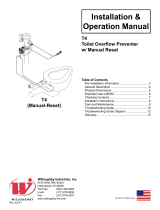
Self-closing Pneumatic Valve-
Operation Details
Hand Push Button (released) Hand Push Button (depressed)
Fixture Backsplash Fixture Backsplash
VALVE CLOSED VALVE OPEN
Three Major Components:
(A) Remote push button assembly
(B) Pneumatic servomotor
(C) Servomotor supply valve
Stainless steel separator cup (D)
divides the servomotor & supply valve�
The only interconnection is magnetic force
Valve Closes: releasing the push button relieves pressure
through the hose barb (8) into the chamber above the
actuating diaphragm (2). The lack of air pressure in this
chamber allows the diaphragm (2) and the magnet (3) to
be forced up. The water side actuating disk (4) drops,
covering the pilot orice (5). Water pressure increases
above the seat diaphragm (6), closing the diaphragm (6)
against the seat (7)�
Valve Opens: Depressing the button (1), forces air through
the chamber above the actuating diaphragm� The air
pressure on top of the actuating diaphragm (2) causes the
diaphragm and magnet (3) to be forced down� The water
side actuating disk (4) is pulled up by magnet (3) opening
the pilot orice (5), bleeding o line pressure from above
the seat diaphragm (6)� Water pressure then lifts the seat
diaphragm (6) o the seat (7) and opens the valve.

Installation & Operation Manual
Stainless Steel 180° Washfountain
WWF-4203-PSL-FT / WWF-4204-PSL-FT
Willoughby Industries, Inc. TOLL FREE (800) 428-4065 ● LOCAL (317) 875-0830 ● FAX (317) 875-0837
Page 16Rev. 1/2019 www.willoughby-ind.com
The Willoughby Pneumatic Valve Assembly is designed as a pressure operated, piloted orice self-closing valve. This type
of valve is used for lavatories as well as showers�
A strainer/checkstop is an integral part of the valve assembly and provides a means of shutting o the water if the valve
needs servicing. A check valve in the checkstop eliminates backow into the supply lines. Fine mesh stainless steel
strainers keep normal line debris from interfering with the mechanical components of the valve.
By virtue of its design, a pneumatic self-closing valve is a normally closed valve� The valve will open when the hand or
foot push button is depressed� The valve will close when the hand or foot push button is released� The operating se-
quence of the valve begins with pressing the push button� Depressing the push button forces air through the tubing into
the air side top cover of the valve� The air pressure on top of the actuating diaphragm causes the diaphragm and magnet
to be forced down. The magnetic force owing through the barrier cup lifts the water side actuating disk. This allows the
water pressure to lift the water side diaphragm o the valve seat and allow water to ow through the valve.
Releasing the push button relieves pressure through the tubing which releases the pressure above the actuating
diaphragm. The lack of air pressure on top of the actuating diaphragm allows the magnet spring to lift the magnet up and
away from the water side actuating disk. The water side spring on top of the water side actuating disk then forces the disk
downward� This seals the pilot hole in the seat diaphragm assembly� The water pressure then increases above the seat
diaphragm which closes the diaphragm against the valve seat and shuts the water o.
A piloted orice in the valve uses the water pressure in the line to assist in opening and closing the valve. The pilot orice
extends through the center of the 3-pronged insert holding the water-side diaphragm and is opened and closed by a
rubber bumper molded onto a stainless steel disk. The bypass orice is molded in the edge of the diaphragm (some
diaphragms may have two of them). All orices must be clear for the valve to function properly.
If a pneumatic valve drips after shutting o and the seat and diaphragm have smooth sealing surfaces, a PVK-2
diaphragm assembly kit should be installed.
If a pneumatic valve does not open and the problem is not in the pneumatic pump or tubing, a PVK-1 motor
assembly kit should be installed.
Self-closing Pneumatic Valve-
Operation and Maintenance

Installation & Operation Manual
Stainless Steel 180° Washfountain
WWF-4203-PSL-FT / WWF-4204-PSL-FT
Willoughby Industries, Inc. TOLL FREE (800) 428-4065 ● LOCAL (317) 875-0830 ● FAX (317) 875-0837
Page 17Rev. 1/2019 www.willoughby-ind.com
(For models with “LSD” option only)
Liquid soap viscosity is measured in “cps” (centipoise). The liquid soap chosen to be used with
Willoughby’s Liquid Soap Dispenser should be between 100cp and 2500cp.
The viscosity of the soap should be thin and free owing.
Some soap types are available in a concentrate and must be diluted with water.
The pH (acidity) level should be in the range of 6.5 to 8.5.
Soap which is too acidic (pH less than 6.5) can corrode stainless steel and degrade rubber, plastic,
or chrome-plated materials.
Soap that is outside the range of 6.5 - 8.5 might be harsh on the hands or skin.
(Generally, any quality soap meeting the viscosity and pH guidelines should work well.)
Recommended Maintenance Schedule
To maintain proper function, Willoughby’s Liquid Soap Dispenser should be cleaned periodically
to remove soap residue. The Liquid Soap Spout should be soaked in hot water for a period of 30
minutes when cleaning is being performed. The soap tray should also be cleaned with hot water.
Liquid Soap Specication and Maintenance

Installation & Operation Manual
Stainless Steel 180° Washfountain
WWF-4203-PSL-FT / WWF-4204-PSL-FT
Willoughby Industries, Inc. TOLL FREE (800) 428-4065 ● LOCAL (317) 875-0830 ● FAX (317) 875-0837
Page 18Rev. 1/2019 www.willoughby-ind.com
INSTALLATION INSTRUCTIONS
Visit our website at http.//www.willoughby-ind.com
2210 West Morris Street • P.O. Box 21217 • Indianapolis, IN 46221
(317) 638-2381 • Fax: (317) 638-6110 • (800) 428-4065
© Rev. 11/2007 Page 13
Care and Maintenance
Solid Surface Care
Stainless Steel Care
Aquasurf® surfaces may be easily cleaned using conventional cleaning agents such as an ammonia
based liquid cleaner, (glass cleaner).
Dry stains on a matte finish can be removed with a 3M Scotch-Brite gray scouring pad or a mild
abrasive cleaner.
Burns or scorches can be removed by sanding with coarse grit sandpaper followed by finer grit (220)
sandpaper. Follow sanding with a 3M Scotch-Brite gray pad (or equivalent) to match finish of sanding
area to surrounding area. A final buffing may be required on polished surfaces. Accidental nicks or
chips can be repaired with special patch kits available in all Aquasurf® colors.
Avoid exposing Aquasurf® surfaces to strong chemicals such as acetone's; paint removers and
sulfuric acid or hydrochloric chemical cleaners. Exposure to strong chemicals may result in perma-
nent damage to Aquasurf® surfaces.
Stainless Steels are basically alloys of iron and chromium, and are corrosion resistant. Stainless
steel has a bright surface that is easy to clean and is free from oxides. Therefore, cleaning of
stainless steel is relatively simple and easy if done on a regular basis.
Frequency of cleaning should depend on the rate at which the fixture becomes dirty. Remember that
fresh (soft) deposits of all kinds are relatively easy to remove, while removing older (hard) deposits
are much more difficult. Establish a cleaning SCHEDULE.
Routine cleaning should involve ordinary soap or detergent and water, applied with a sponge, brush
or cloth. Baking soda, borax or any of several non-abrasive commercial cleansing agents can help
hasten the cleaning action. After scrubbing, rinse THOROUGHLY and wipe dry.
DO NOT use common steel wool, scouring pads, scrapers, wire brushes, files or other steel tools to
clean stainless steel. Such items will scratch the surface or leave small particles of iron imbedded in
the surface, which will eventually rust and stain the surface—even appearing as if the stainless itself
was rusting.
Certain chemical compounds, if used on stainless steel, can give the appearance of rust and if
allowed to stand for long periods of time, can pit the surface of even stainless. Products containing
hydrochloric acid, muriatic acid or potassium hydochloride can ruin the surface.
© Rev. 5/2010
Surfaces may be easily cleaned using conventional cleaning agents such as an ammonia
based liquid cleaner, (glass cleaner)�
Dry stains on a matte nish can be removed with a 3M Scotch-Brite gray scouring pad or a mild
abrasive cleaner�
Burns or scorches can be removed by sanding with coarse grit sandpaper followed by ner grit (220)
sandpaper. Follow sanding with a 3M Scotch-Brite gray pad (or equivalent) to match nish of sanding
area to surrounding area. A nal bung may be required on polished surfaces. Accidental nicks or
chips can be repaired with special patch kits available in all colors.
Avoid exposing surfaces to strong chemicals such as acetone's; paint removers and sulfuric acid or
hydrochloric chemical cleaners� Exposure to strong chemicals may result in permanent damage to
surfaces�
Stainless Steels are basically alloys of iron and chromium and are corrosion resistant� Stainless steel
has a bright surface that is easy to clean and is free from oxides� Therefore, cleaning of stainless
steel is relatively simple and easy if done on a regular basis�
Frequency of cleaning should depend on the rate at which the xture becomes dirty. Remember that
fresh (soft) deposits of all kinds are relatively easy to remove, while removing older (hard) deposits
are much more dicult. Establish a cleaning SCHEDULE.
Routine cleaning should involve ordinary soap or detergent and water, applied with a sponge, brush
or cloth. Baking soda, borax or any of several non-abrasive commercial cleansing agents can help
hasten the cleaning action� after scrubbing, rinse THOROUGHLY and wipe dry�
DO NOT use common steel wool, scouring pads, scrapers, wire brushes, les or other steel tools to
clean stainless steel� Such items will scratch the surface or leave small particles of iron imbedded in
the surface, which will eventually rust and stain the surface - even appearing as if the stainless itself
was rusting�
Certain chemical compounds, if used on stainless steel, can give the appearance of rust and if
allowed to stand for long periods of time, can pit the surface of stainless steel� Products containing
hydrochloric acid, muriatic acid or potassium hydrochloride can ruin the surface�
Care and Maintenance

Installation & Operation Manual
Stainless Steel 180° Washfountain
WWF-4203-PSL-FT / WWF-4204-PSL-FT
Willoughby Industries, Inc. TOLL FREE (800) 428-4065 ● LOCAL (317) 875-0830 ● FAX (317) 875-0837
Page 19Rev. 1/2019 www.willoughby-ind.com
Troubleshooting-
Self-closing Pneumatic Valves
VALVE WILL NOT OPEN OR DELIVER WATER:
(1) Check the plastic tubing that runs from the push button actuator to the pneumatic valve for air leaks.
(2) Make sure the checkstop on the supply to the valve is fully open. Do not partially close the checkstop for any reason
as it is not a throttling valve. The checkstop should be fully open (normal operation) or fully closed (when servicing
the valve)�
(3) Close checkstop and then inspect the strainer in the supply line (installed after the checkstop) to make sure the
strainer is not blocked or partially blocked prohibiting water ow.
(4) Separate valve motor from valve base by removing the (4) #8 screws. Remove the top cover from the motor. Check
the actuator diaphragm for holes� Do not lose the actuator spring�
VALVE WILL NOT SHUT OFF:
(1) Separate valve motor from valve base by removing the four (4) #8 screws�
(2) Inspect the water diaphragm assembly to see if bypass hole in diaphragm is blocked. Remove any debris by blowing
on diaphragm or using force of air� Do not use any tool (such as straight pin) to remove any debris� Enlarging the hole
will shorten or make for erratic cycling.
VALVE CONTINUES TO TRICKLE OR PARTIALLY DELIVER WATER AFTER CYCLE IS OVER:
(1) Inspect seating area on valve base to make sure no debris, pitting or scoring is present.
(2) Clean seat or replace seat (if a brass base) as necessary�
(3) Inspect seating area of diaphragm for debris, clean as necessary� If debris has caused permanent indentations in the
rubber, it may have to be replaced�

/