Page is loading ...

P.O. Box 309, Menomonee Falls, WI 53052-0309
PHONE 1-800-BRADLEY FAX (262) 251-5817
http://www.bradleycorp.com
215-784 Rev. K; EN 05-1608
© 2003 Bradley Corporation
Page 1 of 25 11-18-2005
Installation
Instructions
SN2013/AST4
SN2013/AST4-F
SN2033/AST4
Sentry Corner Washfountain
with Air Valve
Table of Contents
Pre-Installation Information . . . . . . . . . . . . . . . . . .2
Rough-In Specifications . . . . . . . . . . . . . . . . . . .3-7
Installation Instructions . . . . . . . . . . . . . . . . . .8-12
Optional Vented Trap . . . . . . . . . . . . . . . . . . . . . .13
Optional Shroud and Slip Ring . . . . . . . . . . . . . .14
Optional Towel Dispenser on a Shroud . . . . . . . .15
Optional Towel Dispenser on a 1-1/2" Pipe . . . .16
Control Valve Illustrations . . . . . . . . . . . . . . . . . .17
Cleaning and Maintenance . . . . . . . . . . . . . . . . .18
Air Valve Troubleshooting (AST4 and AST4-F) 19-23
Thermostatic Mixing Valve Troubleshooting .24-25
Cleaning the Strainer . . . . . . . . . . . . . . . . . . .24-25
IMPORTANT
Make sure that water supply is completely
off before installation is begun.
When drilling into tile, masonry, or other
hard materials to install wall and floor
anchors, be sure to wear safety goggles to
prevent eye injuries.
Wall anchors used must have a minimum
pull-out rating of 1,000 lbs.
The Sentry Washfountain requires a water
flowing pressure of at least 20 PSI, but no
greater than 80 PSI.
Product warranties may be found under
“Product Information” on our website at
www.bradleycorp.com
SN2013/AST4-F/STD
Floor-Mounted Sentry with
Foot Control
SN2033/AST4
Wall-Mounted Sentry with
Hand Control
U
P
C
R
C

Bradley Corporation • 215-784 Rev. K; EN 05-1608
2
Sentry Corner Washfountain with Air Valves
SN2013/AST4, SN2013/AST4-F, SN2033/AST Installation Instructions
11-18-2005
Pre-Installation Information
Cylindrical air valve
Each of the four sprayheads is controlled by a separate push button cylindrical air valve allowing
each user to activate a single metered flow of water pre-blended to a specific temperature. Air valves
use 0.5 GPM for a ten-second duration, meeting the ANSI/ASHRAE/IES 90A-1980 Standard.
Supplies required for installation:
• 3/8" diameter bolts and floor/wall anchors to anchor washfountain pedestal to floor
or wall
• 1/2" hot and cold water supply lines and fittings (refer to rough-ins on pages 5-7)
• 1/2" nominal copper tubing supply lines for Types with supplies from above
• Standard P-trap (trap included with “B” or “H” drain type and some optional equipment)
• 1-1/2" drain lines and fittings
• Pipe sealant
• OPTIONAL: 1-1/2" vent or tie pipe on types vented through washfountain column
• OPTIONAL: caulk (may be applied between backsplash and bowl to avoid debris
accumulation)

Bradley Corporation • 215-784 Rev. K; EN 05-1608
3
Sentry Corner Washfountain with Air Valve
Installation Instructions SN2013/AST4, SN2013/AST4-F SN2033/AST4
11-18-2005
Sentry Corner Washfountain Dimensions
NOT ADA
COMPLIANT
ADA COMPLIANT
ADA COMPLIANT
WHEN MOUNTED AT
STANDARD HEIGHT
OR JUVENILE HEIGHT

Bradley Corporation • 215-784 Rev. K; EN 05-1608
4
Sentry Corner Washfountain with Air Valves
SN2013/AST4, SN2013/AST4-F, SN2033/AST Installation Instructions
11-18-2005
Sentry Corner Washfountain Rough-ins for Type “A” Drain and Supplies
NOTE: UPC AND IPC RESTRICT THE
VERTICAL DISTANCE FROM THE
FIXTURE OUTLET TO THE TRAP
WEIR TO NOT MORE THAN 24".
CHECK STATE AND LOCAL CODES
FOR VARIANCES.

Bradley Corporation • 215-784 Rev. K; EN 05-1608
5
Sentry Corner Washfountain with Air Valve
Installation Instructions SN2013/AST4, SN2013/AST4-F SN2033/AST4
11-18-2005
Sentry Corner Washfountain Rough-ins for Type “B” Drain and Supplies

Bradley Corporation • 215-784 Rev. K; EN 05-1608
6
Sentry Corner Washfountain with Air Valves
SN2013/AST4, SN2013/AST4-F, SN2033/AST Installation Instructions
11-18-2005
Sentry Corner Washfountain Rough-ins for Type “H” Drain and Supplies

Bradley Corporation • 215-784 Rev. K; EN 05-1608
7
Sentry Corner Washfountain with Air Valve
Installation Instructions SN2013/AST4, SN2013/AST4-F SN2033/AST4
11-18-2005
Sentry Corner Washfountain Rough-ins for Type “O” Drain and Supplies
NOTE: UPC AND IPC RESTRICT THE
VERTICAL DISTANCE FROM THE
FIXTURE OUTLET TO THE TRAP
WEIR TO NOT MORE THAN 24".
CHECK STATE AND LOCAL CODES
FOR VARIANCES.

Bradley Corporation • 215-784 Rev. K; EN 05-1608
8
Sentry Corner Washfountain with Air Valves
SN2013/AST4, SN2013/AST4-F, SN2033/AST Installation Instructions
11-18-2005
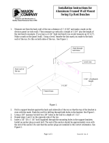
Installation Instructions.
Step 1a: Install and Anchor the Washfountain (for Floor-Mounted Units)
1. Rough in the supply and drain piping as required for your installation (see pages 3-7 for rough-
ins of the optional installations).
2. Install necessary bracing for wall anchors (supplied by installer) for 3/8" bolts at the locations
shown in Figure 1a.
NOTE: Dimensions are the same on both walls from corner.
3. Remove the screws and access panel from the front of the washfountain.
4. Position the washfountain where installation is desired, leveling as required.
5. Using the pedestal as a template, mark the anchor locations on the wall and floor.
6. Install suitable floor and wall anchors (supplied by installer) for 3/8" bolts at the marked locations.
7. Position the washfountain and secure it to the wall and floor anchors with 3/8" bolts (supplied by
installer) leveling as required.
30-1/8"
(765)
29-3/4"
(756)
std. hgt.
3-3/4"
(95)
15-5/16"
(389)
6-1/8"
(156)
25-3/4"
(654)
juv. hgt.
33-9/16"
(852)
std. hgt.
29-9/16"
(751)
juv. hgt.
16-3/4"
(425)
std. hgt.
14-3/4"
(375)
juv. hgt.
34-5/16"
(872)
std. hgt.
30-5/16"
(770)
juv. hgt.
12"
(305)
juv. hgt.
11-1/2"
(292)
std. hgt.
13-11/16"
(348)
juv. hgt.
13-7/16"
(341)
std. hgt.
Figure 1a
Standard and Juvenile Height – Floor-Mounted Sentry Corner Washfountain
Rough-In Notes:
1. Anchor locations shown are to be used to determine reinforcement locations only. Use the fixture as a template for precise
locations when installing anchors.
2. Anchor locations for 3/8" diameter bolts, both supplied by installer.
3. Dimensions shown in parentheses are millimeters.
ADA Compliant: Floor and Wall-mounted models with hand control are ADA compliant when
mounted at standard height or juvenile height.

Bradley Corporation • 215-784 Rev. K; EN 05-1608
9
Sentry Corner Washfountain with Air Valve
Installation Instructions SN2013/AST4, SN2013/AST4-F SN2033/AST4
11-18-2005
Installation Instructions
continued . . .
Step 1b: Install and Anchor the Washfountain (for Wall-Mounted Units)
1. Rough in the supply and drain piping as required for your installation (see pages 3-7 for rough-
ins of the optional installations).
2. Install necessary bracing for wall anchors (supplied by installer) for 3/8" bolts at the locations
shown in Figure 1b.
NOTE: Dimensions are the same on both walls from corner.
3. Remove the screws and access panel from the front of the washfountain.
4. With the help of another person, position the washfountain, leveling as required. Use the pedestal
as a template to mark the wall anchor locations on the wall.
5. Install suitable wall anchors (supplied by installer) for 3/8" bolts at the marked locations.
6. Position the washfountain and secure to the wall with 3/8" bolts (supplied by installer) leveling
as required.
30-1/8"
(765)
34-5/16"
(872)
std. hgt.
30-5/16"
(770)
juv. hgt.
33-9/16"
(852)
std. hgt.
29-9/16"
(751)
juv. hgt.
29-3/4"
(756)
std. hgt.
25-3/4"
(654)
juv. hgt.
23"
(584)
std. hgt.
19-1/4"
(489)
juv. hgt.
17-11/16"
(449)
std. hgt.
13-11/16"
(348)
juv. hgt.
13-9/16"
(344)
14-3/8"
(365)
15-5/16"
(389)
6-1/8"
(156)
Figure 1b
Standard and Juvenile Height – Wall-Mounted Sentry Corner Washfountain
Rough-In Notes:
1. Anchor locations shown are to be used to determine reinforcement locations only. Use the fixture as a template for precise
locations when installing anchors.
2. Anchor locations for 3/8" diameter bolts, both supplied by installer.
3. Dimensions shown in parentheses are millimeters.
ADA Compliant: Floor and Wall-mounted models with hand control are ADA compliant when
mounted at standard height or juvenile height.

Bradley Corporation • 215-784 Rev. K; EN 05-1608
10
Sentry Corner Washfountain with Air Valves
SN2013/AST4, SN2013/AST4-F, SN2033/AST Installation Instructions
11-18-2005
Installation Instructions
continued . . .
Step 2: Make Water Supply Connections
Refer to Figure 2 for AST4 - TMV or AST4 - TL options.
Refer to Figure 3 on the next page for FOOT-TMA or FOOT - TL options
1. Connect 1-1/2" P-trap and drain piping (supplied by installer for “A” and “O” type supplies) to
the drain spud. For “B” and “H” type supplies, or models with optional paper towel dispensers,
use the vented P-trap provided and connect the drain piping as shown in Figure 6 on page 13.
2. Connect the 1/2" NPT female end of the stop/check valves to the supply rough-ins.
IMPORTANT: The hose attached to the hot water inlet of the Vernatherm™ TMV
valve (marked with “H”) must be connected to the hot water rough-in.
3. Connect the supply hoses to the stop/check valves and Vernatherm™ TMV.
4. FOR OPTIONAL SINGLE TEMPERED SUPPLY: Use the single flexible supply hose and stop/check
valve and follow the same procedure for hot and cold supplies as shown below.
Braided Hose
Tempered Line
Adapter
Tempered Line
Supply
Cold Supply Inlet
Hot Supply Inlet
Stop/Check Valve
Vernatherm™ TMV
Solenoid Valve
Assembly
Solenoid Valve
Assembly
1/4" Tube (Black) from
Valve to Aerator
1/4" Tube (Green) from
Valve to Aerator
1/4" Tube (Red) from
Valve to Aerator
1/4" Tube (Black) from
Valve to Aerator
1/4" Tube (Red) from
Valve to Aerator
1/4" Tube (Green) from
Valve to Aerator
1/4-20 x 1/2" Screws
AST4 - TMA
AST4 - TL
1/4-20 x 1/2" Screws
Figure 2

Bradley Corporation • 215-784 Rev. K; EN 05-1608
11
Sentry Corner Washfountain with Air Valve
Installation Instructions SN2013/AST4, SN2013/AST4-F SN2033/AST4
11-18-2005
Installation Instructions
continued . . .
Braided Hose
Tempered Line
Adapter
Tempered Line
Supply
Cold Supply Inlet
Hot Supply Inlet
Stop/Check Valve
Vernatherm™ TMV
Solenoid Valve
Assembly
Solenoid Valve
Assembly
1/4" Tube (Black) from
Valve to Aerator
1/4" Tube (Green) from
Valve to Aerator
1/4" Tube (Red) from
Valve to Aerator
1/4" Tube (Black) from
Valve to Aerator
1/4" Tube (Red) from
Valve to Aerator
1/4" Tube (Green) from
Valve to Aerator
1/4-20 x 1/2" Screws
FOOT - TMA
FOOT - TL
1/4-20 x 1/2" Screws
Figure 3

Bradley Corporation • 215-784 Rev. K; EN 05-1608
12
Sentry Corner Washfountain with Air Valves
SN2013/AST4, SN2013/AST4-F, SN2033/AST Installation Instructions
11-18-2005
Installation Instructions
....Continued
Step 3: Complete the Installation
1. Turn on the water to test the Washfountain.
2. Check to make sure both stop valves are fully open.
3. Push each push button/foot button to purge air from the lines.
Step 4: Adjust Air Metering Valve (Hand-operated pushbutton only)
NOTE: The air valve timer is located next to the tube connector on the air valve body. The timer is
capped with a filter to prevent dirt build-up on the timer. The air valve timing can be adjusting from
0–45 seconds.
1. Adjust the metering timing, if necessary, as outlined below:
• Unscrew the timer cover and use a screwdriver to tighten or loosen the timer (Figure 4).
Turning the timer clockwise increases the time; turning the timer counterclockwise decreases
the time. Be careful not to overtighten as the timer seat can be damaged.
• Continue to adjust until the timer is set at desired length.
• Replace the timer cover over the timer.
NOTE: The Vernatherm™ TMV valve is NOT factory preset. Upon installation, the temperature of
this valve must be checked and adjusted to ensure delivery of a safe water temperature. Water in
excess of 110°F (43°C) may cause scalding.
2. Check the temperature when approximately 1.0 GPM (2 wash stations) water flow is reached and
adjust if necessary (the range of the valve is 95°F–115°F (35°C–43°C). To adjust the
temperature, follow the procedure below:
• Loosen temperature locking nut with wrench.
• Using a blade screwdriver, turn the adjustment stem counterclockwise to increase the
temperature or clockwise to decrease the temperature (Figure 5).
• Once desired temperature is reached, tighten nut to prevent temperature change.
3. Refasten the access panel with the screws supplied.
TIMER ASSEMBLY
TIMER COVER
Figure 4
TEMPERATURE
ADJUSTMENT
STEM
TEMPERATURE
LOCKING
NUT
Figure 5

Bradley Corporation • 215-784 Rev. K; EN 05-1608
13
Sentry Corner Washfountain with Air Valve
Installation Instructions SN2013/AST4, SN2013/AST4-F SN2033/AST4
11-18-2005
Installation Instructions (Optional) Vented Trap
Used for all “B” and “H” drain installations and also for “A” and “O” drain
installations when towel dispensers are required.
Step 1: Installation
1. Install 1-1/2" NPT vent piping (supplied by installer) and trap to 1-1/2" NPT drain as shown in
Figure 6.
P-TRAP
1-1/2" DRAIN
(supplied by
installer)
1-1/2" NPT VENT
PIPE (supplied by
installer)
1-1/2" NPT TEE
1-1/2" NPT CLOSE
NIPPLE
DRAIN
SPUD
STRAINER
TAILPIECE
Figure 6

Bradley Corporation • 215-784 Rev. K; EN 05-1608
14
Sentry Corner Washfountain with Air Valves
SN2013/AST4, SN2013/AST4-F, SN2033/AST Installation Instructions
11-18-2005
Installation Instructions
continued . . .
Install Optional Shroud and Slip Ring
1. Slide the shroud and
slip ring over the 1-1/2"
NPT vent pipe
(supplied by installer).
2. Install the vent pipe
with the shroud to the
1-1/2" NPT tee, and
attach the tailpiece, trap
and drain assemblies
(see Figure 7).
3. Secure the slip ring to
the ceiling with five
1/4" diameter screws
(supplied by installer)
(see Figure 7 for slip
ring mounting pattern.
4. Secure the shroud to
the bracket on the
sprayhead module
cover with the shroud
screws provided (see
Figure 7).
Figure 7
FIVE 1/4" DIA. HOLES,
EQUALLY SPACED
ON A 6" DIA. CIRCLE
SLIP RING
1-1/2" NPT DRAIN
(supplied by installer)
1-1/2" NPT “Y” TEE
1-1/2" NPT VENT PIPE
(supplied by installer)
P-TRAP
TAILPIECE
1-1/2" NPT CLOSE NIPPLE
SHROUD SCREW
SOAP FILLER HOLE CAP
BOLT-ON BACKSPLASH
SPRAYHEAD MODULE
1-1/2" NPT VENT PIPE
(supplied by installer)
FINISHED CEILING
SLIP RING MOUNTING
HOLE PATTERN
SHROUD

Bradley Corporation • 215-784 Rev. K; EN 05-1608
15
Sentry Corner Washfountain with Air Valve
Installation Instructions SN2013/AST4, SN2013/AST4-F SN2033/AST4
11-18-2005
Installation Instructions
continued . . .
Install Towel Dispenser on a Shroud (Optional)
1. Slide the shroud,
mounting brackets, and
slip ring over the 1-1/2"
NPT vent pipe (supplied
by installer).
2. Install the vent pipe with
the shroud and mounting
brackets to the 1-1/2"
NPT tee and attach the
tailpiece, trap and drain
assemblies (Figure 8).
3. Secure the slip ring to
the ceiling with five 1/4"
diameter screws
(supplied by installer)
(see Figure 8 for slip
ring mounting pattern).
4. Secure the shroud to the
bracket on the sprayhead
module cover with the
shroud screws provided
(see Figure 8).
5. Using the back of the
towel dispenser as a
template, secure the
brackets to the shroud
with the set screws
provided (see Figure 8).
This will correctly space
the mounting brackets.
6. Place the towel
dispenser on the brackets
as shown in Figure 8 and
secure towel dispenser to
the brackets with the #10
sheet metal screws
provided.
7. Attach (2) support
brackets from back side
of top mounting bracket
to wall using suitable
anchors.
Figure 8
1-1/2" NPT DRAIN
(supplied by installer)
1-1/2" NPT “Y” TEE
1-1/2" NPT VENT PIPE
(supplied by installer)
P-TRAP
TAILPIECE
1-1/2" NPT CLOSE NIPPLE
BOLT-ON BACKSPLASH
SPRAYHEAD MODULE
FIVE 1/4" DIA. HOLES,
EQUALLY SPACED
ON A 6" DIA. CIRCLE
SLIP RING
FINISHED CEILING
SLIP RING MOUNTING
HOLE PATTERN
SHROUD
SOAP FILLER HOLE CAP
SHROUD SCREW
TOWEL DISPENSER
#10 SHEET
METAL SCREWS
MOUNTING BRACKET

Bradley Corporation • 215-784 Rev. K; EN 05-1608
16
Sentry Corner Washfountain with Air Valves
SN2013/AST4, SN2013/AST4-F, SN2033/AST Installation Instructions
11-18-2005
Installation Instructions
continued . . .
Install Towel Dispenser on a 1-1/2" Pipe (Optional)
1. Slide the spacer sleeve, one
mounting bracket, tie bar, and
the second mounting bracket
(in that order) over the 1-1/2"
NPT pipe (supplied by
installer).
2. Install the 1-1/2" NPT pipe
with spacer, brackets, and tie
bar to the 1-1/2" NPT tee and
attach the tailpiece, trap and
drain assemblies (Figure 9).
3. Using the back of the towel
dispenser as a template,
secure the tie bar to the 1-1/2"
pipe with the set screws
provided, and then secure the
upper mounting bracket to the
tie bar with the two hex head
bolts supplied. This will
correctly space the mounting
brackets (see Figure 9).
4. Place the towel dispenser on
the brackets as shown in
Figure 9 and secure towel
dispenser to the brackets with
the #10 sheet metal screws
provided.
5. Plug the end of the 1-1/2"
pipe with the pipe cap
provided.
6. Attach (2) support brackets
from back side of top mounting
bracket to wall using suitable
anchors.
Figure 9
1-1/2" NPT DRAIN
(supplied by installer)
1-1/2" NPT “Y” TEE
1-1/2" NPT VENT PIPE
(supplied by installer)
P-TRAP
TAILPIECE
1-1/2" NPT CLOSE NIPPLE
BOLT-ON BACKSPLASH
SPRAYHEAD
MODULE
TIE BAR
PIPE CAP
SOAP FILLER HOLE CAP
TOWEL DISPENSER
1-1/2" NPT
VENT PIPE
(supplied by
installer)
MOUNTING BRACKET
HEX HEAD BOLT
SPACER SLEEVE
#10 SHEET METAL
SCREWS

Bradley Corporation • 215-784 Rev. K; EN 05-1608
17
Sentry Corner Washfountain with Air Valve
Installation Instructions SN2013/AST4, SN2013/AST4-F SN2033/AST4
11-18-2005
Installation Instructions
continued . . .
Control Valve Illustrations (Figures 10a and 10b)
NOTE: On all valve and push button arrangements, all tubing going to a valve set is the same color.
SPRAYHEAD
AERATOR
1/8" O.D.
CONTROL
TUBE
HAND CONTROL
1/4" O.D.
SUPPLY
TUBE
AIR VALVE
PUSH BUTTON
FOOT PUSH
BUTTON
FOOT CONTROL
AERATOR
1/8" O.D.
CONTROL TUBE
1/4" O.D.
SUPPLY TUBE
AIR VALVE
Figure 10a
Figure 10b

Bradley Corporation • 215-784 Rev. K; EN 05-1608
18
Sentry Corner Washfountain with Air Valves
SN2013/AST4, SN2013/AST4-F, SN2033/AST Installation Instructions
11-18-2005
Cleaning and Maintenance Instructions for Stainless Steel
Material Description: Stainless steel is extremely durable, and maintenance is simple and inexpensive.
Proper care, particularly under corrosive conditions, is essential. Always start with the simplest solution and
work your way toward the more complicated.
Routine cleaning: Daily or as often as needed use a solution of warm water and soap, detergent, or
ammonia. Apply the cleaning solution per the manufactures instructions and always use a soft cloth or
sponge to avoid damaging the finish.
Stubborn Stains: To remove stains from stainless steel use a stainless steel cleaner and polish such as Ball
®
stainless steel cleaner or a soft abrasive. Always follow the manufactures instructions and apply in the same
direction as the polish lines.
IMPORTANT: NEVER USE ORDINARY STEEL WOOL OR STEEL BRUSHES ON
STAINLESS STEEL. ALWAYS USE STAINLESS STEEL WOOL OR
STAINLESS STEEL BRUSHES.
Special Situations for Material
Fingerprints and Smears: To remove fingerprints or smears use a high quality stainless steel cleaner and
polish in accordance with the manufactures instructions. Many of these products leave a protective coating
the helps prevent future smears and fingerprints.
Grease and Oil : To remove grease and oil use a quality commercial detergent or caustic cleaner. Apply in
accordance to the manufactures instructions and in the direction of the polish lines.
Precautions: Avoid prolonged contact with chlorides (bleaches, salts), bromides (sanitizing agents),
thiocyanates (pesticides, photography chemicals, and some foods), and iodides on stainless steel equipment,
especially if acid conditions exist.
IMPORTANT: DO NOT PERMIT SALTY SOLUTIONS TO EVAPORATE AND DRY ON
STAINLESS STEEL.
The appearance of rust streaks on stainless steel leads to the belief that the stainless steel is rusting. Look for the
actual source of the rust in some iron or steel particles which may be touching, but not actually a part of the
stainless steel structure.
NOTE: Strongly acidic or caustic cleaners may attack the steel causing a reddish film to appear. The use of
these cleaners should be avoided.
Brand Names: Use of brand names is intended only to indicate a type of cleaner. This does not constitute an
endorsement, nor does the omission of any brand name cleaner imply its inadequacy. Many products named
are regional in distribution, and can be found in local supermarkets, department and hardware stores, or
through your cleaning service. It is emphasized that all products should be used in strict accordance with
package instructions.

Bradley Corporation • 215-784 Rev. K; EN 05-1608
19
Sentry Corner Washfountain with Air Valve
Installation Instructions SN2013/AST4, SN2013/AST4-F SN2033/AST4
11-18-2005
Troubleshooting Air Valve Metering Hand Control (AST4)
CAUTION: Turn off water supplies to unit before troubleshooting.
Problem: One or more individual operating stations fail to turn on.
Cause: Incoming water pressure is over 80 PSIG.
Solution: Reduce water pressure to below 80 PSIG.
Install a pressure-reducing valve at the building main set to the manufacturer's recommendations.
Lower line pressure will improve the performance and extend the life of all the plumbing in the
building.
Problem: An individual operating station fails to turn on.
Cause: A failed diaphragm/magnet assembly.
Solution: Test the station to determine cause.
1. Unscrew the valve clamp nut on the top of the valve (see Figure 11a on Page 22).
2. Remove valve cover. If the diaphragm/magnet assembly comes out with the cover, gently peel
the diaphragm away form the cover, taking care not to damage the diaphragm. Inspect the
diaphragm for any holes of tears. A damaged diaphragm needs to be replaced.
3. Insert the diaphragm/magnet assembly back into the valve, but leave the cover off.
4. Gently press the diaphragm until it is fully depressed. The valve should activate. If not, the
diaphragm/magnet assembly needs to be replaced.
Problem: One or more individual operating stations turn off too quickly or run too long.
Cause: Timing requires adjustment.
Solution: Readjust timing (see Page 12, step 4).
Problem: An individual operating station cannot be adjusted to run for more than five seconds.
Cause: Air tube connection leak.
Solution: Check 1/8" tubing connection.
1. Tighten compression nut at 1/8" tubing connection to air valve in pedestal.
2. If leak persists, remove the sprayhead cover and check the 1/8" elbow tube connection behind
the pushbutton assembly. Make sure the screw holding the elbow is tight and the fitting in the
elbow is firmly hand tightened. Make sure the tubing is pushed firmly into the fitting.
3. If leak persists, reseat the 1/8" tubing. Disconnect the tubing from the fitting by pressing down
on the plastic ring at the top of the fitting while firmly pulling the tubing out of the fitting. Trim
½" off the end of the tubing squarely with a razor-sharp knife and push the tubing firmly back
into the connector to make sure it is seated.
4. If the leak still persists, loosen the compression nut on the air valve inside the pedestal and pull
the tubing out of the fitting. Trim ½" off the end of the tubing squarely, with a razor-sharp knife.
Then slide the tubing through the nut until ½" of tubing is exposed. Insert tubing into the
compression fitting on the valve body and hand tighten the compression nut.

Bradley Corporation • 215-784 Rev. K; EN 05-1608
20
Sentry Corner Washfountain with Air Valves
SN2013/AST4, SN2013/AST4-F, SN2033/AST Installation Instructions
11-18-2005
Troubleshooting Air Valve Metering Hand Control (AST4)
....Continued
Problem: An individual operating station won't turn off and drips.
Cause: There is debris trapped between the diaphragm and valve seat.
Solution: Remove debris between the diaphragm and valve seat.
1. Remove the three Phillips-head screws that hold the air valve together. Be careful not to lose the
armature or spring (see Figure 11a on Page 22).
2. Remove the diaphragm. Remove any debris trapped between the diaphragm and the valve seat.
3. Rinse off the diaphragm and inspect for damage. Make sure the center orifice and the two small
side orifices are open.
4. Reassemble in reverse order, being careful not to over tightening the Phillips-head screws or you
may crack the plastic valve body. Tighten until the armature plate makes contact with the plastic
body.
Problem: An individual station will not shut off.
Cause: Timing mechanism is clogged.
Solution: Clear the timing mechanism.
1. If the timer cover has been sprayed with water, wait at least two minutes. It will shut off and
return to normal operation once it dries off.
2. If it doesn't turn off remove the timer cover. If the valve shuts off the cover is clogged and needs
to be replaced.
3. If the valve still doesn't turn off, turn the adjusting screw counter clockwise until it can be
removed from the valve body.
4. Wipe adjusting screw thoroughly with a lint-free towel making sure that there is no water or
debris on the adjusting screw.
5. Use a pipe stem cleaner to wipe the inside of the timer body if possible.
6. Replace timer-screw and adjust valve timing.
7. Replace timer cover.
/