Page is loading ...

CET - s.r.l.
Vers. 1.0
LBM 62 ID
Pag. 1
CET
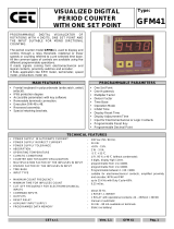
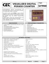
DIGITAL DIFFERENTIAL
COUNTER
WITH TWO THRESHOLDS
Type:
LBM62ID
6 DIGITS VISUALIZED DIGITAL COUNTER WITH
TWO THRESHOLDS, SUITABLE TO OPERATE WITH
SINGLE DIRECTIONAL COUNTINGS
THE COUNTER LBM 62 ID FINDS APPLICATION
WHERE THERE IS THE NECESSITY TO VISUALIZE
AND TO CONTROL, THROUGH TWO
PROGRAMMABLE THRESHOLDS, THE DIFFERENCE
BETWEEN TWO INPUTS OF SINGLE DIRECTIONAL
COUNTINGS.
MAIN FEATURES
PROGRAMMABLE PARAMETERS
• Frontal keyboard in polycarbonate (antiscratch, antioil,
antiacid).
• IP65 protection degree
• Accessible parameters with key software
• Removable terminals connection.
• Execution DIN 48 x 96.
• Recessed assembly.
• Special retaining brackets.
• Two Threshold
• Reset Time
• Multiplication factor of the impulses
• Input (Slow / Fast)
• Count (Up / Down / Superior)
• Reset key
• Decimal Point
• Counting Input
TECHNICAL FEATURES
•
POWER SUPPLY IN ALTERNATE CURRENT
•
POWER SUPPLY IN DIRECT CURRENT
•
POWER SUPPLY TOLERANCE
•
ABSORPTION
•
OPERATING TEMPERATURE
•
CLIMATIC CONDITIONS
•
COUNTER VISUALIZATION
•
BATCH COUNTER VISUALIZATION
•
MULTIPLICATION COEFFICIENT THE INPULSES IN
INPUT
•
INPUT TYPE (NPN or PNP)
•
MINIMUM TIME FOR SLOW INPUT SIGNALS
•
CUT FREQUENCY FOR ELECTROMECHANICAL
INPUTS
•
AUXILIARY INPUTS POWER SUPPLY
(version /5 /12 /24 VDC on demand)
•
COMMAND INPUTS
•
OUTPUTS
•
RELAY RESET
•
PROGRAMMED DATA MEMORY
: Single power 24 - 110 - 230 Vac (50 / 60 Hz).
: Single power 24 Vdc
: +10% - 15%.
: 2 W - 3 VA.
: -5 °C + 55 °C.
: U.R. 95 % at 40 °C (without condensate).
: 6 digits, 14mm high
: 5 digits, 14mm high
: Programmable from 0,00001 to 9,99999
.
: Suitable for Single directional Encoder, Proximity, electromechanical
and logical signals up to 20KHz.
: Programmable in 25%, 50% and 75% of the frequency.
: from 25 to 100 Hz.
: 24 Vdc - 80 mA available on terminals.
: 12 Vdc - 80 mA available on terminals..
: 5 Vdc - 80 mA available on terminals.
: Counter Reset
: Inhibit Counter 1
: Inhibit Counter 2
: 2 relays with operating contacts - capacity 2A - 250Vac.
: Manual or automatic with excitation time from 0,1 to 99,9 sec.
: static (no battery)

CET - s.r.l.
Vers. 1.0
LBM 62 ID
Pag. 2
DESCRIPTION OF THE FRONTAL KEYBOARD
ø
YELLOW
The key 'LEFT ARROW' in normal operating phase visualizes, blinking, all the programmings executed
without the limitation of the insertion code. The time of scansion of the programmings is given from the
pressure of the same key. It exits automatically from this phase after 5 sec of the last pressure of the
same key.
In programming phase it moves the cursor of the figure towards left of a step, than at the beginning it is
on the right side first one on the. At the end it resumes from the first one to right.
ù
YELLOW
In programming phase it increases the value of the blinking figure.
ú
BLUE
The key 'PRG' pressed for 2 sec. allows to enter in the programming phase, visualizing on display
C.0000.
In the programming phase, pressing key 'PRG' impulsively, it exits from the programming phase. The
instrument exits automatically from the programming phase, 60 sec. after the pressure of the last key.
û
RED
The key 'ENT/RES' in normal phase of counting has the 'RESET' function, with the modalities to it
attributed in the programming phase.
In programming phase it confirms and memorizes the visualized data and passes to the successive
function. If it has arrived to list end it resumes from the beginning.
INPUTS / OUTPUTS DESCRIPTION
DC POWER
(inputs 1 - 2) 24V DC Power Supply of the instrument.
AC POWER
(inputs 3 - 4) Power Supply of the instrument; it can be to 24 - 110 - 230 VAC according to demand.
24 VDC - 80mA
(inputs 6 - 7) 24 VDC - 80 mA auxiliary Power Supply that the instrument supply to feed Encoder and amplified
proximity.
RESET
(input 8) Input of RESET that executes the reset of the visualized count showed on display at the moment of its
activation.
INHIBIT 1
(input 9) When active, it operates as inhibit of the counting CNT1 INC
INHIBIT 2
(input 10)
When active, it operates as inhibit of the counting CNT 2 DEC
CNT 1 INC
(input 11) NPN counting input (PNP on demand) suitable for electromechanical contacts, amplified proximity, 3
wires sensors and single directional Encoders; it executed the increasing of the counter.
CNT 2 DEC
(input 12) NPN counting input (PNP on demand) suitable for electromechanical contacts, amplified proximity, 3
wires sensors and single directional Encoders; it executed the decreasing of the counter.
RL1
(inputs 14-15-16)
Output of Relay 1, connected to the operation of the Threshold S1. The Common and Normally Opened
contacts are available.
RL2
(inputs 17-18-19)
Output of Relay 2, connected to the operation of the Threshold S2. The Common and Normally Opened
contacts are available.
DESCRIPTION OF THE LED’S OPERATION
LED 1 It comes activated to the reaching of the Threshold S1.
LED 2 It comes activated to the reaching of the Threshold S2.

CET - s.r.l.
Vers. 1.0
LBM 62 ID
Pag. 3
PROGRAMMING OF THRESHOLD
For THRESHOLDS programming access, proceed as follow:
- Press key ‘PRG’ in impulsive mode; on display appears:
Ë1 <
999999
S.1 = THRESHOLD 1, value programmable between 000000 and 999999 of the CNT1 INC counter that
executes the increment of the counting. If it programmed = 0 the set point control is excluded.
Ë2 <
999999
S.2 = THRESHOLD 2, value programmable between -99999 and 999999 of the CNT2 DEC counter that
executes the decrement of the counting. If it programmed = 0 the set point control is excluded.
Key ENT confirms the data and passes to the successive programming. In order to exit the programming, press key PRG.
PROGRAMMING OF THE OPERATION PARAMETERS
The programmable parameters are divided in two groups and protect with a 4 figures code.
In order to approach the programming, proceed in the following way:
- Press key PRG for about 2 sec. On the display appears:
Cod
0000
GROUP 1
:
insert code
2357
and press
ENT
.
Ì
õ
0©0
t.’ = Automatic Time Reset of CNT1 INC counter, programmable from 00,0 up to 99,9 sec. This
parameter allows to the instrument to operate in automatic mode. When the counting reach the S1 value
automatically it resets the counting, excites the relay RL1 and restart the counting without lose impulses.
The relay RL1 remains ON for time programmed in t.’ programming. If the reset time programmed in t.’ is =
0 (00,0) the instrument operates in manual mode.
Particular case: if the set up time t.’ is smaller of the time employed from the count to arrive to the values
of S.1 or S.2, the relative relays will never come unactived.
Ì
"
0©0
t.” = Automatic Time Reset of CNT2 DEC counter, programmable from 00,0 up to 99,9 sec. This
parameter allows to the instrument to operate in automatic mode. When the counting reach the S2 value
automatically it resets the counting, excites the relay RL2 and restart the counting without lose impulses.
The relay RL2 remains ON for time programmed in t.” programming. If the reset time programmed in t.” is
= 0 (00,0) the instrument operates in manual mode.
Particular case: if the set up time t.’ is smaller of the time employed from the count to arrive to the values
of S.1 or S.2, the relative relays will never come unactived.
F
õ
¨
20
F’ = 4 digits multiplier Factor of CNT1 INC counter, programmable from 0,1 to 9.99999.This parameter
allows to convert the number of the input impulses, showing them on the display in another format. If it
programmed = 0 it comes reprogrammed automatically to 1. If a value lower than 1 is inserted, it obtains
the division of the impulses. Es. I want to divide for 25 the impulses in input; calculation 1 : 25 = 0.04.
Attention: the variation of the value of the multiplying modifies automatically the value of the counting.
F
"
¨
20
F.” = 4 digits multiplier Factor of CNT2 DEC counter, programmable from 0,1 to 9.99999.This
parameter allows to convert the number of the input impulses, showing them on the display in another
format. If it programmed = 0 it comes reprogrammed automatically to 1. If a value lower than 1 is inserted,
it obtains the division of the impulses. Es. I want to divide for 25 the impulses in input; calculation 1 : 25 =
0.04.
Attention: the variation of the value of the multiplying modifies automatically the value of the counting.
In
õ
Ë
In. ’ = Input CNT1 = Fast - Slow - Medium. This programming allows to set the input of CNT1 counter to
read electromechanical signals or logical signals:
In = F. Fast, input CNT1 can read logical signals up to 20 KHz.
In = S. Slow, input CNT1 can read electromechanical signals up to 25 Hz.
In = M. Medium, input CNT1 can read electromechanical or logical signals up to 100 Hz.
In
"
Ë
In. ” = Input CNT2 = Fast - Slow - Medium. This programming allows to set the input of CNT2 counter to
read electromechanical signals or logical signals:
In = F. Fast, input CNT2 can read logical signals up to 20 KHz.
In = S. Slow, input CNT2 can read electromechanical signals up to 25 Hz.
In = M. Medium, input CNT2 can read electromechanical or logical signals up to 100 Hz.
SUÈ õ Ñ
SUÈ õ æ
SUP’ = Programming of Superior counting of CNT1 INC counter.
SUP.’ = Y ; Superior counting active; when the counting reaches the threshold, the instrument actives the
RL1 relay and continues to count. (valid only with t’ = 0).
SUP.’ = n.; Superior counting excluded.

CET - s.r.l.
Vers. 1.0
LBM 62 ID
Pag. 4
SUÈ " Ñ
SUÈ " æ
SUP.” = Programming of Superior counting of CNT1 INC counter.
SUP.” = Y ; Superior counting active; when the counting reaches the threshold, the instrument actives the
RL1 relay and continues to count. (valid only with t’ = 0).
SUP.” = n.; Superior counting excluded.
Key ENT confirms the data and passes to the successive programming. In order to exit the programming, press key PRG.
PROGRAMMING OF THE OPERATION PARAMETERS
The programmable parameters are divided in two groups and protect with a 4 figure code.
In order to approach the programming, proceed in the following way:
- Press key PRG for about 2 sec. On the display appears:
Cod
0000
GROUP 2
:
insert code
2413
and press
ENT
.
NeÆ
Ñ
NeÆ
æ
Active or excluded memory.
This parameter allows to program the saving of the current counter value during the power off
the instrument.
MEM. Y. = memorization of the count during the power off. When power on the instrument the
display will visualize the last present value in the power off phase.
MEM. n. = excluded memorization of the count; every time that the instrument comes powered
off and then powered on the count comes lost and the instrument restart always from the initial
condition.
ȼ 0
ȼ
5
Programming of the Decimal Point.
This programming allows to add a decimal point to the visualization on the 5 digits, in order to
obtain counts with various resolutions.
d.p. = 0 Decimal Point excluded; visualization 999999
d.p. = 1 Decimal Point on the second display from right; visualization 99999,9
d.p. = 2 Decimal Point on the third party display from right; visualization 9999,99
d.p. = 3 Decimal Point on the quarter display from right; visualization 999,999
d.p. = 4 Decimal Point on fifth display from right; visualization 99,9999
d.p. = 5 Decimal Point on fifth display from right; visualization 9,99999
Attention, the Decimal Point is only fictitious, it doesn't realize any conversion.
0í1 î
0í1 ÷
Programming of the OUTPUT 1 RL1. This parameter allows to activate the RL1relay to the
beginning
î
or to the end
÷
of the count.
Ou.1
î
= the Activation of the RL1 relay to end of count
Ou.1
÷
= the Activation of the RL1 relay to beginning of count
0í2 î
0í2 ÷
Programming of the OUTPUT 2 RL2. This parameter allows to activate the RL1relay to the
beginning
î
or to the end
÷
of the count.
Ou.2
î
= Activation of the RL2 relay to end of count
Ou.2
÷
= Activation of the RL2 relay to beginning of count
¹È
È
¹È
ê
Activation mode of the programmed parameters.
With this programming is possible to activate the executed programmings directly during the programming
or, when exited of the programming, after a RESET (with frontal key or from rear input)
A.P. = P. Activation of the parameters in Immediate mode: the programmed data works immediately .
A.P. = r. Activation of the parameters to the exit of the programming after a RESET.
Key ENT confirms the data and passes to the successive programming. In order to exit the programming, press key PRG.

CET - s.r.l.
Vers. 1.0
LBM 62 ID
Pag. 5
NOTE
DIAGRAMMI DI FUNZIONAMENTO
FUNZIONAMENTO CON RESET AUTOMATICO
S1 > 0
S2 = 0
t.‘ diverso da 0
t.” diverso da 0
SUP. ‘ = n. = escluso
SUP. “ = n. = escluso

CET - s.r.l.
Vers. 1.0
LBM 62 ID
Pag. 6
NOTE
DIAGRAMMI DI FUNZIONAMENTO
FUNZIONAMENTO CON RESET AUTOMATICO
S1 > 0
S2 = 0
t.‘ diverso da 0
t.” diverso da 0
SUP. ‘ = n. = escluso
SUP. “ = n. = escluso

CET - s.r.l.
Vers. 1.0
LBM 62 ID
Pag. 7
DECLARATION OF ‘CE’ CONFORMITY
Borgolavezzaro , October , 03rd 2005
The building firm:
CET S.r.l.
Head office:
Strada Statale 211, Km 53,3
28071 Borgolavezzaro (No) ITALY
declare that the product:
type:
Digital Electronic Counter
model:
LBM62 ID
use class:
Industrial
is in conformity with the following normatives:
EN55011
ENV50141
ENV50204
EN61000-4-2
EN61000-4-4
The manufacturing:
CET S.r.l.
________________________________
Signature
SENSORS CONNECTIONS
KEY
6
8
9
10
11
12
7
LBM Terminals
GND
CNT2
CNT1
INHIBIT
RESET
RESTART
+24VDC
PNP SENSORS
7
8
9
10
11
12
6
LBM Terminals
+24VDC
CNT2
CNT1
INHIBIT
RESET
RESTART
GND
NPN SENSORS
Contatto
Voltage
Level
Open
collector
Transistor
Encoder,
Proximity
amplified or
3 wires
Bi-directional
Encoder

CET - s.r.l.
Vers. 1.0
LBM 62 ID
Pag. 8
CONNECTIONS IN NEGATIVE LOGIC NPN
CONNECTIONS IN POSITIVE LOGIC PNP
24 VDC POWER SUPPLY
TRANSISTORS OUTPUTS
OVERALL DIMENSIONS (mm)
FRONTAL
SIDE
REAR
DRILL TEMPLATE
CET
CETCET
CET
CET
CETCET
CET
s.r.l.
Strada Statale 211 Km 53,550
28071 Borgolavezzaro - NO - ITALY
Tel : ++39 0321-885180/885301/885807
Fax : ++39 0321-885560
info@cet-italy.com
www.cet-italy.com
Agent:
158
130
9
19
44x92
REMOVABLE
TERMINALS
RETA
INING
BRACKETS
10
MAX
93
45
48
96
ENT
RES
PROG
L1
L2
863259
Electronic counter
LBM
CET
-
8
9
10
11
12
13
19
18
17
16
15
14
CNT1
CNT2
NPN
RL2 RL1
RESET INHIBIT 2
INHIBIT1
12Vdc
80mA
+
-
DC AC
POWER SUPPLY
-
+
7
1
2
3
4
5
6
8
9
10
11
12
13
19
18
17
16
15
14
CNT1
CNT2
PNP
RL2 RL1
RESET INHIBIT 2
INHIBIT1
24Vdc
80mA
+
-
DC AC
POWER SUPPLY
-
+
7
1
2
3
4
5
6
12Vdc
80mA
+
-
DC AC
POWER SUPPLY
-
+
7
1
2
3
4
5
6
Max. Voltage 30VDC - Max. Current 100 mA
When the instrument
is fed to 24 VDC
connect the input 5
and 7 as showed.
92
44
1 2 3 4 5 6 7 8 9 10 11 12 13
19 18 17 16 15 14
OUT2
OUT1
19
18
17
16
15
14
/