Page is loading ...

1E
2E

i
To ensure long, trouble-free operation, please
read this manual carefully.
Precautions
Location
Using the unit in the following locations can result in a mal-
function.
• In direct sunlight
• Locations of extreme temperature or humidity
• Excessively dusty or dirty locations
• Locations of excessive vibration
Power supply
Please connect the designated AC/AC power supply to an
AC outlet of the correct voltage. Do not connect it to an AC
outlet of voltage other than that for which your unit is
intended.
The AC/AC power supply will produce a certain amount of
heat during operation, but this is not a malfunction. When
power is connected, place it in a well ventilated location,
and avoid placing it on a plastic object or where heat
buildup might occur.
Interference with other electrical devices
This product contains a microcomputer. Radios and televi-
sions placed nearby may experience reception interfer-
ence. Operate this unit at a suitable distance from radios
and televisions.
Handling
To avoid breakage, do not apply excessive force to the
switches or controls.
Care
If the exterior becomes dirty, wipe it with a clean, dry cloth.
Do not use liquid cleaners such as benzene or thinner, or
cleaning compounds or flammable polishes.
Keep this manual
After reading this manual, please keep it for later refer-
ence.
Keeping foreign matter out of your equipment
• Never set any container with liquid in it near this equip-
ment. If liquid gets into the equipment, it could cause a
breakdown, fire, or electrical shock.
• Be careful not to let metal objects get into the equip-
ment. If something does slip into the equipment,
unplug the AC/AC power supply from the wall outlet.
Then contact your nearest Korg dealer or the store
where the equipment was purchased.
THE FCC REGULATION WARNING (for U.S.A.)
This equipment has been tested and found to comply with
the limits for a Class B digital device, pursuant to Part 15 of
the FCC Rules. These limits are designed to provide rea-
sonable protection against harmful interference in a resi-
dential installation. This equipment generates, uses, and
can radiate radio frequency energy and, if not installed and
used in accordance with the instructions, may cause harm-
ful interference to radio communications. However, there is
no guarantee that interference will not occur in a particular
installation. If this equipment does cause harmful interfer-
ence to radio or television reception, which can be deter-
mined by turning the equipment off and on, the user is
encouraged to try to correct the interference by one or
more of the following measures:
• Reorient or relocate the receiving antenna.
• Increase the separation between the equipment and
receiver.
• Connect the equipment into an outlet on a circuit differ-
ent from that to which the receiver is connected.
• Consult the dealer or an experienced radio/TV techni-
cian for help.
Unauthorized changes or modification to this system can
void the user’s authority to operate this equipment.
CE mark for European Harmonized Standards
CE mark which is attached to our company’s products of
AC mains operated apparatus until December 31, 1996
means it conforms to EMC Directive (89/336/EEC) and CE
mark Directive (93/68/EEC). And, CE mark which is
attached after January 1, 1997 means it conforms to EMC
Directive (89/336/EEC), CE mark Directive (93/68/EEC)
and Low Voltage Directive (73/23/EEC).
Also, CE mark which is attached to our company’s products
of Battery operated apparatus means it conforms to EMC
Directive (89/336/EEC) and CE mark Directive (93/68/
EEC).

ii
Table of Contents
Introduction......................................1
Features..................................................................... 1
Printing conventions in this manual............................. 2
Panel overview of the D16 .................................3
Top panel .................................................................. 3
Front panel ................................................................ 5
Rear panel................................................................. 7
Objects in the LCD screen and their
functions......................................................8
Objects in the LCD screen............................................ 8
Adjusting the contrast of the LCD screen...................... 8
Basic operations in the LCD screen .............................. 9
1. Select the mode.........................................................9
2. Select the tab page....................................................9
3. Select the parameter and make settings................9
Undo..............................................................................10
Basic operation...............................11
Step 1. Making connections, and turning the
power on/off.............................................11
Connecting audio devices to the D16, and turning
the power on ........................................................... 11
1. Connections.............................................................11
2. Turning the power on/off.....................................12
Listening to the demo songs...................................... 13
Step 2. Creating or selecting a song..................14
Creating or selecting a song ..................................... 14
1. Creating a new song...............................................14
2. Naming a song........................................................14
3. Selecting an existing song .....................................14
Step 3. Recording.............................................16
1. Selecting the input/record track............................ 16
Analog inputs...............................................................16
Digital input .................................................................18
2. Adjusting the record level, and recording.............. 18
Recording on a virtual track...................................... 19
Overdubbing – recording another track while you
listen to a previously-recorded track.......................... 19
Punching-in/out – re-recording a specific area .......... 19
Manual punch-in/out.................................................19
Auto punch-in/out......................................................20
Bouncing – combining multiple tracks into one or
two tracks................................................................ 21
Recording 14 tracks of audio and 2 external
input sources to the remaining 2 tracks ...................21
Recording 16 tracks to overwrite 2 of the tracks.....21
Recording 16 tracks of audio to 2 currently
unselected virtual tracks.............................................22
Other recording methods.......................................... 22
Step 4. Playback..............................................23
Playback.................................................................. 23
Program play........................................................... 23
Other playback methods .......................................... 23
Step 5. Changing the time location....................24
Switching the counter display....................................24
Changing the current time location ............................24
Using Scrub Playback to find precise locations ...........24
Step 6. Using the mixer....................................25
Adjusting the volume ................................................25
Adjusting the stereo position......................................25
Using EQ to adjust the tone .......................................25
Applying EQ to the track playback ..........................25
Applying input EQ to the analog inputs/
Recording with input EQ ...........................................26
Pairing .....................................................................26
Monitoring adjustments.............................................27
Solo settings .............................................................27
Registering/recalling a scene.....................................28
Step 7. Using effects.........................................29
Overview of the effects..............................................29
Insert effects .............................................................29
Applying the insert effects while you record
(analog/rhythm only).................................................30
Applying an insert effect to a track during
playback........................................................................31
Master effects ...........................................................31
How the master effects can be used..........................31
Using the master effects..............................................31
Final effect................................................................32
How the final effect can be used ...............................32
Using the final effect ...................................................32
Editing an effect........................................................32
Controlling an effect from an external device .............33
Using an external effect ............................................34
Step 8. Mixdown..............................................35
Recording to a master tape .......................................35
Using the sub inputs..................................................35
Step 9. Track editing ........................................36
Track editing procedure.............................................37
Basic track editing procedure ....................................37
Step 10. Song editing.......................................38
Song editing procedure.............................................38
Basic song editing procedure.....................................38
Step 11. Rhythm/tempo settings.......................39
Playing rhythms........................................................39
Specifying and playing a rhythm..............................39
Recording your performance while you listen to
the rhythm....................................................................39
Recording the rhythm.................................................39
Setting the tempo......................................................40
Manual tempo..............................................................40
Tempo map...................................................................40
Tempo track..................................................................41
Step 12. Song saving .......................................43
Copy Song, Copy All Songs.......................................43
Backup/Restore...........................................................43

iii
Reference.......................................45
1. COUNTER....................................................45
Counter: Counter display...........................................45
2. SYSTEM....................................................... 45
P1Control: Foot switch/control change device (pedal/
MIDI) settings .......................................................45
P2MIDI: MIDI settings ...............................................46
Using a MIDI sequencer to control stop/play/
fast-forward/rewind/record/locate on the D16
(Control by MMC).......................................................46
P3Sync: Synchronization settings..............................46
Synchronizing a MIDI sequencer to the D16...........47
P4DiskUtil: Initializing/formatting/checking a
drive....................................................................47
Connecting an external drive.....................................48
Turning the external drive power on/off................48
Initializing and formatting a disk .............................48
Using a removable disk..............................................48
P5B–U/Rst: Backing-up and restoring data to
removable disk ....................................................49
Backup procedure........................................................50
Restore procedure........................................................50
3. RECORD ...................................................... 51
P1RecMode: Selecting the recording mode................51
P2Bounce: Settings for bounce recording...................51
4. TRACK.........................................................52
P1Vtr1–8: Select virtual tracks 1–8............................52
P2Vtr9–16: Select virtual tracks 9–16........................52
P3EditTrk: Track editing............................................53
Examples of track editing...........................................56
5. SONG.........................................................59
P1SelSong: Selecting a song.....................................59
P2EditSong: Song editing .........................................59
Examples of song editing ...........................................61
P3PrgPlay: Program playback of songs.....................62
P4CDR/RW: Creating and playing a CD-R/RW..........62
Procedure for creating an audio CD.........................63
6. STORE.........................................................64
7. MARK.......................................................... 64
P1Mark: Editing marks.............................................64
Registering a mark ......................................................64
Moving to a mark location.........................................64
Deleting a mark............................................................64
8. SCENE......................................................... 65
P1ReadDel: Scene playback on/off and editing.........65
Procedure for registering a scene..............................66
Automatically switching scenes while the
song plays.....................................................................66
Recalling a scene..........................................................66
Copying a scene...........................................................66
Editing and overwriting a scene................................66
Deleting a scene ...........................................................67
Moving the time location of a registered scene.......67
Filtering scenes.............................................................67
Using MIDI to control scenes.....................................67
P2MixView: Pan/fader scene display........................67
9. TEMPO/RHYTHM ......................................... 68
P1SetUp: Tempo and rhythm settings........................68
P2TmpMap: Editing the tempo map ..........................68
P3TmpTrk: Create a tempo track...............................69
10. IN/LOC1, OUT/LOC2, TO/LOC3,
END/LOC4.................................................70
Registering a locate point ([IN/LOC1], [OUT/
LOC2], [TO/LOC3], [END/LOC4]) .........................70
Moving to a locate point.............................................70
Locate functions...........................................................70
11. AUTO PUNCH............................................71
P1AtPunch: Settings for auto punch-in/out recording. 71
12. LOOP ........................................................72
P1Loop: Loop playback/recording settings................ 72
Loop playback procedure...........................................72
Loop recording procedure .........................................72
13. UNDO.......................................................73
14. TRIGGER....................................................73
P1Trigger: Settings to start trigger recording............. 73
Procedure for trigger recording.................................74
15. SCRUB.......................................................74
Using the Scrub function:...........................................75
16. ENTER .......................................................75
17. INPUT........................................................75
P1Ch1–8: Select the inputs for mixer
channels 1–8....................................................... 75
P2Ch9–16: Select the inputs for mixer
channels 9–16..................................................... 76
P3InEq1–4: EQ settings for inputs 1–4 ...................... 76
P4InEq5–8: EQ settings for inputs 5–8 ...................... 77
P5Tuner: Tuner ........................................................ 77
Using the tuner ............................................................77
18. EQ/PHASE.................................................78
P1Eq1–4: EQ settings for mixer channels 1–4 ........... 78
P2Eq5–8: EQ settings for mixer channels 5–8 ........... 78
P3Eq9–16: EQ settings for mixer channels 9–16 ....... 78
P4Phase: Phase settings for mixer channels .............. 78
19. INSERT EFFECT ...........................................79
P1InsAss: Insert effect insertion location/type............ 79
P2InsEff1: Selection and settings for Insert
Effect 1................................................................ 80
P3InsEff2: Selection and settings for Insert
Effect 2................................................................ 81
P4 InsEff3: Selection and settings for Insert
Effect 3................................................................ 81
P5InsEff4: Selection and settings for Insert
Effect 4................................................................ 81
P6Ins5–8: Selection and settings for Insert
Effects 5–8........................................................... 81
20. MASTER EFFECT/AUX/FINAL EFFECT...........81
P1MstEff1: Selection and settings for master effect 1 . 81
P2MstEff2: Selection and settings for master effect 2 . 82
P3EffSnd1:
Send settings for effect 1...................................... 82
P4EffSnd2:
Send settings for effect 2...................................... 82
P5AuxSend:
External send settings........................................... 82
P6FinalEff: Selection and settings for the final effect... 83
21. SOLO/MONITOR .......................................84
P1Solo: Solo select................................................... 84
P2Monitor: Monitor settings ..................................... 84
22. METER/TRACK VIEW..................................85

iv
23. TRACK STATUS...........................................86
24. PAN/BALANCE..........................................86
25. FADER.......................................................86
26. TRANSPORT KEYS......................................87
Effect Parameter List........................89
Insert (2in2outx2)/Master/Final Effect...............89
Reverb RV1 – RV7
Category: Reverb-type effects............................... 89
1: RV1: Reverb Hall......................................................89
2: RV2: Smooth Hall.....................................................89
3: RV3: Reverb Wet Plate.............................................89
4: RV4: Reverb Dry Plate.............................................89
5: RV5: Reverb Room ...................................................89
6: RV6: Bright Room.....................................................89
7: RV7: Early Reflections..............................................89
Delay DL1 – DL6
Category: Delay-type effects................................. 89
8: DL1: L/C/R Delay...................................................89
9: DL2: St/Cross Delay................................................90
10:DL3: St.Multitap Delay............................................90
11:DL4: St.Modulation Delay.......................................90
12:DL5: St.Dynamic Delay ...........................................90
13:DL6: St.Auto Panning Delay...................................91
Modulation MO1– MO7
Category: Modulation-type effects ........................ 91
14:MO1: St.Chorus.........................................................91
15:MO2: St.Flanger........................................................91
16:MO3: St.Phaser..........................................................91
17:MO4: St.Vibrato .......................................................91
18:MO5: St.Tremolo.......................................................92
19:MO6: St.Auto Pan.....................................................92
20:MO7: Ensemble.........................................................92
Dynamics DY1 – DY7
Category: Dynamics-type effects........................... 92
21:DY1: St.Compressor.................................................92
22:DY2: St.Limiter..........................................................92
23:DY3: Multiband Limiter..........................................93
24:DY4: St.Gate ..............................................................93
25:DY5: St.Exciter/Enhancer .......................................93
26:DY6: St.Decimator....................................................93
27:DY7: St.Paramtrc 4band EQ....................................94
Special Effect SE1 – SE4
Category: Special Effect........................................ 94
28:SE1: St.Ring Modulator............................................94
29:SE2: Doppler..............................................................94
30:SE3: St.Analog Record .............................................94
31:SE4: Talking Modulator...........................................94
Insert (2in2outx2), Final ...................................95
Large size LS1 – LS7
Category: Large size effects.................................. 95
32:LS1: St.Graphic 7band EQ.......................................95
33:LS2: St.Multiband Limiter.......................................95
34:LS3: Vocoder .............................................................95
35:LS4: St.Pitch Shifter..................................................95
36:LS5: Early Reflections L...........................................95
37:LS6: Rotary Speaker .................................................96
38:LS7: Center Canceller...............................................96
Insert (1in2outx2).............................................96
GT1 – GT6 Category: Guitar multi............................. 96
39:GT1: Guitar Multi1...................................................96
40:GT2: Guitar Multi2...................................................96
41:GT3: Guitar Multi3 ..................................................96
42:GT4: Guitar Multi4 ..................................................96
43:GT5: Guitar Multi5 ..................................................96
44:GT6: Guitar Multi6 ..................................................96
AS1 – AS3 Category: Guitar amp simulator ...............96
45:AS1: Amp Simulator1.............................................. 96
46:AS2: Amp Simulator2.............................................. 96
47:AS3: Amp Simulator3.............................................. 96
PA1 Category: Pre-amp simulator..............................97
48:PA1: Pre Amp Simulator ........................................97
EB1 – EB3 Category: Bass multi .................................97
49:EB1: Bass Multi1....................................................... 97
50:EB2: Bass Multi2....................................................... 97
51:EB3: Bass Multi3....................................................... 97
MS1 Category: Mic multi...........................................97
52:MS1: Mic Multi......................................................... 97
VO1 – VO2 Category: Vocal multi.............................97
53:VO1: Vocal Multi1 ...................................................97
54:VO2: Vocal Multi2 ...................................................97
Effects within multi-effect programs GT1–VO2, and
their parameters.......................................................97
Dist.................................................................................. 97
NR....................................................................................97
Comp............................................................................... 97
P4EQ ...............................................................................97
Exctr ................................................................................97
Wah................................................................................. 97
Filter................................................................................ 97
AmpSim..........................................................................98
CabRes............................................................................ 98
Tone................................................................................. 98
Gate.................................................................................98
DeEss...............................................................................98
Cho/Fl ............................................................................98
Treml............................................................................... 98
Phaser.............................................................................. 98
Delay...............................................................................98
S.Dly................................................................................98
Pitch.................................................................................98
MicSim............................................................................99
Insert (1in1outx4).............................................99
55:MM1: P4EQ – Exciter...............................................99
56:MM2: P4EQ – Wah ..................................................99
57:MM3: P4EQ – Cho/Flng......................................... 99
58:MM4: P4EQ – Phaser............................................... 99
59:MM5: P4EQ – Mt.Delay.......................................... 99
60:MM6: Comp – Wah .................................................99
61:MM7: Comp – AmpSim.......................................... 99
62:MM8: Comp – OD/HiG.......................................... 99
63:MM9: Comp – P4EQ................................................ 99
64:MM10: Comp – Cho/Flng...................................... 99
65:MM11: Comp – Phaser............................................ 99
66:MM12: Comp – Mt.Delay ....................................... 99
67:MM13: Exciter – Comp............................................ 99
68:MM14: Exciter – Limiter .......................................100
69:MM15: Exciter – Cho/Flng................................... 100
70:MM16: Exciter – Phaser......................................... 100
71:MM17: Exciter – Mt.Delay.................................... 100
72:MM18: Limiter – P4EQ.......................................... 100
73:MM19: Limiter – Cho/Flng..................................100
74:MM20: Limiter – Phaser........................................ 100
75:MM21: Limiter – Mt.Delay................................... 100
76:MM22: OD/HiG – Cho/Flng............................... 100
77:MM23: OD/HiG – Phaser..................................... 100
78:MM24: OD/HiG – Mt.Delay................................ 100
79:MM25: OD/HiG – AmpSim................................. 100

v
80:MM26: Wah – AmpSim .........................................100
81:MM27: Decimator – AmpSim...............................100
82:MM28: Decimator – Comp....................................100
83:MM29: Cho/Flng – Mt.Delay ...............................100
84:MM30: Phaser – Cho/Flng....................................100
85:MM31: AmpSim – Tremolo...................................100
86:MM32: Reverb – Gate.............................................100
87:MM33: MicSim - Limiter........................................100
Effects within multi-effect programs MM1–MM33, and
their parameters.....................................................100
P4EQ ..............................................................................100
Excit1 .............................................................................100
Excit2 ............................................................................100
Wah................................................................................100
Comp1 ...........................................................................100
Comp2 ...........................................................................100
Limitr.............................................................................101
AmpSim ........................................................................101
MicSim...........................................................................101
Decima...........................................................................101
ODHiG .........................................................................101
ChFl1..............................................................................101
ChFl2..............................................................................101
Phaser ............................................................................101
Treml..............................................................................101
Mt.Dly............................................................................101
Reverb............................................................................101
Gate................................................................................101
Insert (1in1outx8)........................................... 102
88:MN1: OverDrive/HighGain.................................102
89:MN2: Compressor2 ................................................102
90:MN3: Limiter...........................................................102
91:MN4: Gate................................................................102
92:MN5: Exciter2..........................................................102
93:MN6: Parametric 4band EQ..................................102
94:MN7: Amp Simulator.............................................102
95:MN8: Multitap Delay.............................................102
96:MN9: Chorus/Flanger2.........................................102
97:MN10: Phaser..........................................................102
98:MN11: Expander.....................................................102
Effect Control.................................................102
Cntrl...............................................................................102
Appendices ..................................103
Troubleshooting............................................. 103
Messages ...................................................... 106
Updating the system software ........................107
D16 specifications.......................................... 108
MIDI implementation chart .............................110
Block diagram ............................................... 111
Effect Program List .........................................112
Rhythm Name List (215patterns)..................... 114
Demo Song List.............................................. 115
Index............................................................. 116
Handling of the internal
hard disk
Do not apply physical shock to this device. In partic-
ular, you must never move this device or apply
physical shock while the power is turned on. This
can cause part or all of the data on disk to be lost, or
may damage the hard disk or interior components.
When this device is moved to a location where the
temperature is radically different, water droplets
may condense on the disk drive. If the device is used
in this condition, it may malfunction, so please allow
several hours to pass before operating the device.
Do not repeatedly turn the power on/off. This may
damage not only the D16, but also any SCSI devices
that are connected.
This device begins to access the hard disk immedi-
ately after the power is turned on.
Never turn off the power while the HDD access indi-
cator is lit or blinking. Doing so can cause all or part
of the data on disk to be lost, or may cause malfunc-
tions such as hard disk damage.
If the hard disk has been damaged due to incorrect
operation, power failure, or accidental interruption
of the power supply, a fee may be charged for
replacement even if this device is still within its
warrantee period.
* Company names, product names, and names of for-
mats etc. are the trademarks or registered trade-
marks of their respective owners.

Introduction
1
Introduction
• The D16 is a 16 track digital multi-track recorder
(MTR) with full-digital processing (
24 bit
internal
processing,
16/24 bit
uncompressed
recording and
playback,
44.1 kHz
sampling frequency).
• It contains a
16 track
recorder, a
24-channel 8-bus
mixer, and effects.
When using
16 bit
recording/playback:
8
tracks can
be recorded simultaneously, and
16
tracks can be
played back simultaneously.
When using
24 bit
recording/playback:
4
tracks can
be recorded simultaneously, and
8
tracks can be
played back simultaneously.
From recording to effect processing to mixing down
to CD-R/RW (a CD-R/RW drive is required), DAT
recorder or MIXDOWN,
all processing is per-
formed completely in the digital domain
.
•A
2.1 GB
hard disk is built-in, allowing a total of up
to
6.5 hours
of recording (when recording one track
at 16 bits). A maximum of
100
songs
×
16
tracks × 8
virtual tracks can be recorded, for a total maximum
of 12,800 tracks of data.
• All analog inputs in the mixer section use high-per-
formance balanced preamps to take full advantage
of the audio quality of full-digital processing.
Dedicated XLR input and guitar input jacks are pro-
vided, and support a range from mic level to +16
dBu (beyond pro audio level) so that virtually any
audio source can be connected.
All phone jack inputs use TRS balanced jacks to
support balanced input. Of course, unbalanced
input is also supported.
The D16 has a built-in mic that lets you immedi-
ately record phrases that come to mind.
The S/P DIF digital input provides a sampling rate
converter that automatically converts 48 kHz or 32
kHz sources to 44.1 kHz.
• Each analog input/mixer channel provides high
EQ, mid EQ, and low EQ. The mid EQ has an
adjustable cutoff frequency.
Since separate EQ is provided for the inputs and the
mixer, you will never have the problem of uninten-
tional “double EQ” that can occur on MTR systems
with an analog mixer, when the EQ settings used
during recording are re-applied during playback.
A maximum of eight insert effects can be used on the
analog inputs/mixer channels. Two master effects
accept sends from each channel. And lastly, a dedicated
final effect can be applied to the master outputs. Insert
effects and master effects can be selected from 128/32/32
(total of 192) different preset programs, each of which
combine up to five of 98 varieties of high-quality effect
with settings created by professional musicians and stu-
dio engineers. You can freely edit the preset programs
and store them in one of 192 user areas. An expression
pedal (separately sold option) can be connected to con-
trol an insert effect in realtime.
• The effects built into the D16 make it easy for you to
use detailed and powerful modeling sounds pro-
duced by Korg’s “ ” modeling technology.
•A tuner is built in, so that you can tune an instru-
ment etc. whose sound is picked up by the internal
mic, or check the tuning of a playback track.
• Fader, EQ, pan, and effect settings etc. of the mixer
section can be stored as scenes, and up to 100 scenes
can be recorded in each song. Scenes can be
switched as time elapses during playback, or you
can recall them when desired as general-purpose
settings.
• Operations such as record, copy, and delete are per-
formed using non-destructive editing. You can use
the Undo function to return to the state before
recording or editing, and then use the Redo function
to cancel the Undo operation. Undo allows you to
return through the previous 99 recording or editing
operations.
• The Auto Save function ensures that songs or
phrases that you created by recording or editing are
automatically saved to disk when you switch songs
or turn off the power, freeing you from having to
manually save your data.
• Each track provides eight virtual tracks.
When recording solo parts etc., you can switch
between virtual tracks to record multiple takes, and
select the best one later. Or when bouncing (ping-
pong recording), you can specify an “unselected vir-
tual track” as the recording destination, so that six-
teen tracks of recorded data can be mixed down to
two tracks without erasing any of the sixteen tracks.
By repeatedly bouncing sixteen tracks to two tracks,
you can theoretically create a song with 16 × 8 = 128
tracks without erasing any of the original track data.
• In addition to the metronome sound, the D16 pro-
vides 215 different rhythm patterns in a wide range
of musical styles, which can provide a recording
guide with a more realistic sense of tempo. Even
without connecting a rhythm machine, it’s easy to
begin recording along with a favorite rhythm. These
rhythm patterns can also be recorded on a track.
• Auto and manual punch-in/out recording functions
make it easy for you to re-record a specific portion of
your performance that you would like to redo.
• The Trigger Record function can automatically ini-
tiate recording when audio input occurs, so that it’s
easy to begin recording even if both hands are occu-
pied with playing a guitar or keyboard. A foot
switch can also be used to start/stop recording.
Thank you for purchasing the Korg D16 Digital
Recording Studio. To ensure trouble-free enjoy-
ment, please read this manual carefully and use
the instrument as directed.
Features

2
• The Scrub function lets you audition the recorded
state of each track just as if you were using an open-
reel tape recorder, making it easy to find the precise
beginning of a desired phrase, etc.
• The Locate Point (four locations per song) and Mark
Point (100 locations per song) memory functions
allow you to memorize points for instant recall, such
as divisions in the song structure. You can assign a
name to each mark.
• The D16 provides a Program Playback function sim-
ilar to that found on a CD or MD, so that you can
playback multiple songs in a specified order. This
function can also be used to produce your own
album that can be recorded directly to MD or DAT
etc.
• You can connect a CD-R/RW drive and produce
your own original albums (a CD-R/RW drive is
required).
Be aware that some audio CD players are unable to
play back CD-R/RW discs.
• When recording and editing songs or phrases from a
record or CD, you can tap along to the tempo to
match the tempo. You can also create a tempo map,
or record MIDI Clock data from an external device.
• The D16 can be synchronized to a sequencer or
rhythm machine etc. that supports MIDI Clock,
MTC, or MMC.
• Major types of connectors such as SCSI and S/P DIF
digital interface etc. are standard, allowing immedi-
ate connection to external devices.
The SCSI connector allows recording/playback or
data backup on an external hard disk or removable
disk etc.
The S/P DIF connectors allow audio data to be digi-
tally recorded from an external digital device such
as a CD or MD, or a song you create to be mixed
down to DAT or MD via direct digital output.
The AUX OUT jack allows an external effect to be
connected.
• The D16 features the TouchView system that allows
you perform operations by directly touching the
LCD screen, making cursor movements easy. A four-
directional cursor key is also provided to allow tra-
ditional operation.
• The D16 is compact and lightweight, and can be eas-
ily carried into the studio or anywhere else.
Switches and knobs [ ]
Keys, dials, and knobs on the panel of the D16 are
printed within [square brackets].
Parameters that appear in the LCD screen “ “
Parameters that appear in the LCD screen are printed
inside “double quotation marks.” The terms ‘button’
and ‘tab’ refer to objects in the LCD screen.
Bold-face type
Panel settings such as for faders or the [TRACK STA-
TUS] keys are printed in bold type, and parameter val-
ues are printed in “bold type.”
Bold type also indicates content within the text that we
wish to emphasize.
Example: The currently selected tab page
The following figure shows the [MASTER
EFFECT/AUX] “MstEff1” tab page. To select this
tab page, press the [MASTER EFFECT/AUX] key
located on the top panel, and press the “MstEff1”
tab in the LCD screen.
The various objects in the tab page are parameters
etc. There are also under-bars, popup buttons, and
icons.
In the figure shown, “Ef
fectNumber,” “RetLev”
and “Rename” buttons etc. are parameters. Cur-
rently, “Ef
fectNumber” is highlighted, and can be
edited. The current value is “M001,” and this will
change if you rotate the [VALUE] dial. (→p.9)
Steps 1 2 3 …
Steps in a procedure are indicated as 1 2 3 …
Selecting a parameter
There are two ways to select a parameter on the D16.
You can directly press that parameter in the LCD
screen, or you can use the [CURSOR] key and the
[ENTER] key to move to the parameter (→p.9). In this
owner’s manual, the explanations will usually use the
method of directly pressing the LCD screen.
p.■■
This indicates a page or parameter number for refer-
ence.
Symbols ,
These symbols respectively indicate cautions or advi-
sory explanations.
LCD screens
The parameter values shown in the LCD screens
printed in this manual are explanatory examples, and
may not necessarily match the displays that appear on
your D16.
What is ?
(Resonant structure and Electronic circuit
Modeling System) is KORG’s proprietary sound
modeling technology which precisely reproduces the
complex character and nature of both acoustic and
electric instruments as well as electronic circuits in
real world environments. emulates a wide
variety of sound generation characteristics including
instrument bodies, speakers & cabinets, acoustic
fields, microphones, vacuum tubes, transistors, etc.
Printing conventions in this
manual

3
Introduction
Panel overview of
Panel overview of the D16
1 LCD screen
The D16 uses a TouchView system based on a
touch panel screen. By pressing objects that are
shown in the LCD screen, you can select pages,
tabs, and parameters, and set their values.
During recording/playback, this area displays vol-
ume data (level meters), time data (locator), and
various parameters. (→p.8)
2 [TRACK STATUS] keys
These keys are used to put each track into playback
or record status, or to mute (silence) it. Each time
you press a key, the track setting will alternate
(LED color lit, dark). (→p.86)
When recording from analog/digital input, you
can select up to eight recording tracks.
These settings can be paired.
3 [PAN] knobs (Ch 1…8)
[BALANCE] knobs (Ch 9…16)
These knobs adjust the stereo location of each
channel.
For channels 1–8 they adjust the pan of each chan-
nel. For channels 9–16 they adjust the balance.
(→p.86)
These settings can be paired, and registered in
a scene.
4 [CHANNEL] faders
(Ch1…8, Ch9/10…15/16)
These faders adjust the recording/playback vol-
ume of each channel.
Channels 9–16 are stereo faders. (→p.86)
These settings can be paired, and registered in
a scene.
5 [MASTER] fader
This fader sets the overall volume of all channels.
When bouncing, it sets the recording level of the
bounce destination tracks. (→p.86)
6 [INPUT] key
This key is used to select the mixer channel to
which the audio signal from each input will be
Top panel
1
2
3
4
5
678
910
11
12 13 1415
16
17
18
19
20
21
22
23
24 25
26
27
28
29
30
31
32
* For the mic and trim controls etc., refer to the “Front panel” section.

4
sent. It is also used to specify EQ (for recording) for
the analog inputs.
You will also select this key when using the tuner.
(→p.26, 75)
7 [EQ/PHASE] key
This key is used to specify the EQ (for track play-
back) and phase of each channel. (→p.25, 78)
These settings can be paired, and registered in
a scene.
8 [INSERT EFFECT] key
This key is used to select the location of an insert
effect, to select the effect type, and to select and
edit effect programs. (→p.29, 79)
These settings can be registered in a scene.
9 [MASTER EFFECT/AUX] key
This key is used to select and edit effect programs
for master effects 1 and 2, and to set the send levels
from each channel to the master effects. In addi-
tion, it is used to set the send amount to an external
effect, and to select and edit effect programs for the
master effects. (→p.31, 81)
These settings can be registered in a scene. The
send settings can be paired.
10 [SOLO/MONITOR] key
This key is used to solo an individual channel,
send, or return. It is also used to select an audio
source for monitoring. (→p.84)
When solo is on, the LED will blink.
11 [METER/TRACK VIEW] key
This key is used to display volume data (level
meters) during recording and playback, and to
view audio event data in each track (track view).
(→p.85)
12 [SYSTEM] key
This key is used to make foot switch and MIDI-
related settings, to manage data on disk, and to
backup or restore data. (→p.45)
13 [RECORD] key
Press this key to make recorder settings such as
selecting the recording source or the bounce
recording method etc. (→p.51)
14 [TRACK] key
Press this key to select the virtual track for each
track, or to perform track editing operations such
as copy or delete. (→p.52)
15 [SONG] key
Press this key to create a new song, rename/select
a song, perform a song editing operation such as
copy or move, perform program playback of
songs, or produce an audio CD (a CD-R/RW drive
is required). (→p.59)
16 [STORE] key
To register a locate point, mark, or scene, press this
key to register the time. The registered time can be
stored to a location key by pressing the corre-
sponding key. (→p.64)
17 [MARK] key
This key is used to register time locations within a
song, and to jump immediately to a registered loca-
tion.
It is also used to edit marks by renaming or delet-
ing them etc. (→p.64)
18 [SCENE] key
This key is used to store settings of the [CHAN-
NEL] faders, [PAN]/[BALANCE] knobs, EQ, and
effect send effects. to the desired location of a song
as a Scene. When Scene is on, playing back the
song will cause the registered scenes to switch
automatically. This key is also used to perform
scene editing operations such as copy, rename, or
delete. (→p.65)
This key will light when the Scene function is on.
19 [TEMPO/RHYTHM] key
This key is used to set the tempo for a song, create
a tempo map, and turn the rhythm function on/
off. (→p.68)
This key will light when the Rhythm function is
on.
20 [IN/LOC1] key, [OUT/LOC2] key,
[TO/LOC3] key, [END/LOC4] key
These keys are used to register a desired time loca-
tion within a song, or to instantly jump to a regis-
tered time location.
The time locations registered here are used as the
punch-in/out locations, and the editing range for
track editing operations such as copy or delete.
(→p.70)
By holding down the [IN/LOC1] key and pressing
the [OUT/LOC2] key, you can listen to the audio
between the IN–OUT points.
21 [AUTO PUNCH] key
This key is used to turn the Auto Punch-in/out
function on/off, to set the pre/post roll time, and
to verify the start/end locations. (→p.71)
This key will light when the Auto Punch-in/out
function is on.
22 [LOOP] key
This key is used to turn the Loop function on/off
for playback or recording, and to verify the start/
end locations. (→p.72)
This key will light when the Loop function is on.
23 [UNDO] key
This key accesses the Undo function which lets you
return data to its original state after recording or
editing a track, and the Redo function which

5
restores the state prior to Undo.
The previous 99 recording or editing operations
can be undone. (→p.73)
This key will light when the Undo function is
available.
24 [TRIGGER] key
This is the on/off key for the Trigger Recording
function, which causes recording to begin auto-
matically in response to an audio input. This key is
also used to set the threshold level and pre-trigger
time. (→p.73)
This key will light when the Trigger Recording
function is on.
25 [SCRUB] key
This is the on/off key for the Scrub, Play To/From,
and Slow Play functions. These functions are used
by operating the corresponding controller. (→p.74)
This key will light when the Scrub function is on.
26 [ENTER] key
This key is used to finalize a parameter selection or
to turn it on/off. It has the same result as directly
pressing the LCD screen.
27 [CURSOR] key
This key moves the cursor.
28 [VALUE] dial
This dial is used to modify various values, and to
move the current time location.
When the Scrub function is on, rotating the dial
will playback the track at the corresponding speed.
29 TRANSPORT keys
[REC] key, [RHSL] key, [PLAY] key,
[STOP] key, [REW] key, [FF] key
These keys control recorder operations such as
playback and record. (→p.87)
30 [POWER] key
This key turns the power on/off. (→p.12)
31 HDD access indicator
This indicator will light when the internal hard
disk is being accessed for recording, playback, or
editing etc.
32 MIDI indicator
This indicator will light when MIDI data is being
received from the MIDI IN connector.
1 MIC (built-in mic)
2 [MIC] on indicator
3 [MIC] switch: OFF, INPUT 1, INPUT 2
OFF: The built-in mic is turned off. (LED dark)
INPUT 1: The built-in mic is input from [INPUT 1].
(LED lit)
INPUT 2: The built-in mic is input from [INPUT 2].
(LED lit)
When the [MIC] switch is set of the INPUT 1 or
INPUT 2, that input will used as the mic input, and
the source connected to that jack will not be input.
The input priority order is as follows.
•1 [MIC], 2 [GUITAR IN] , 3 [INPUT]
If you are not using the built-in mic, set the [MIC]
switch to OFF so that sound from the mic is not
input.
4 [GUITAR IN] jack
A guitar or bass guitar can be input here.
This is an unbalanced 1/4" (6.3 mm) input jack
with 1 M-ohm impedance.
5 [INPUT 1], [INPUT 2] jacks
Audio sources such as mic or line (keyboard etc.)
can be connected here.
These are combination type jacks that combine an
XLR jack and a 1/4" jack TRS phone jack.
Both jacks are balanced inputs.
Front panel
1
2
9
7
3
46810115
Introduction
Panel overview of

6
Unbalanced phone plugs can also be connected.
Be aware that if you plug into the [GUITAR IN]
jack, nothing can be input from the [INPUT 1] jack.
If you wish to input a source to the [INPUT 1] jack,
you must remove the plug from the [GUITAR IN]
jack.
6 [INPUT 3], [INPUT 4] jacks
Audio sources such as mic or line (keyboard etc.)
can be connected here.
These are balanced inputs with 1/4" TRS phone
jacks. Unbalanced phone plugs can also be con-
nected.
7 [TRIM] knobs: –60…–10…+4 dBu
These knobs adjust the input level. The markings
indicate the input level. Adjust these as appropri-
ate for your input device.
The LEDs will show different colors to indicate the
following statuses.
Lit green: input present
Lit orange: correct level
Lit red: excessive level
Adjust these knobs so that the LEDs do not light
red.
Although the input level will depend on your
equipment and performance, here are some gen-
eral guidelines for adjusting these knobs.
–40 – –60 dBu: mic input
–30 dBu: guitar, bass guitar
–10 dBu: consumer audio equipment such as CD
players
+4 dBu: keyboards and studio equipment
If the [TRIM] knob is raised excessively for an
input to which nothing is connected, you may hear
hum or noise.
8 [PHONES] jack
Headphones can be connected here.
This is a 1/4" stereo phone jack.
It outputs the same audio signal as [MONITOR
OUT L/R].
9 [PHONES LEVEL] knob: 0…10
This knob adjusts the volume level of the head-
phones. Higher settings will increase the volume.
10 [FOOT SWITCH] jack
If both your hands are occupied with playing an
instrument etc., you can use a foot switch to per-
form basic operations of the D16’s recorder.
The foot switch can be used to play/stop, start/
end manual punch recording, register a mark, and
register tap tempo etc. (→p.45)
Connect a foot switch (separately sold option, PS-1
etc.) to this jack.
11 [EXPRESSION PEDAL] jack
You can use a pedal to control a specified parame-
ter of an insert effect. You can control the parame-
ter in realtime while you play or record. (→p.33)
Connect an expression pedal (separately sold
option, EXP-2, XVP-10 etc.) to this jack.
Balanced phone plug Unbalanced phone plug
GND COLD HOT
GND HOT
1/4" TRS phone jack
XLR jack
1: GND
2: HOT
3: COLD
3
1
2

7
1 [AC 9V] connector
Connect the included AC/AC power supply to this
connector.
2 [MIDI OUT] connector
MIDI messages are transmitted from this connec-
tor. Use this when you wish to control a connected
external MIDI device from the D16. (→p.46)
3 [MIDI IN] connector
MIDI messages are received at this connector. Use
this when you wish to control the D16 from a con-
nected external MIDI device. (→p.46)
4 [LCD CONTRAST] knob
This knob adjusts the contrast of the LCD screen.
The visibility of the LCD screen will depend on
your viewing angle, so adjust this knob as neces-
sary. When viewed from the front panel, rotating
this knob toward the right will darken the charac-
ters, and rotating it toward the left will lighten the
characters.
5 [SCSI] connector
An external hard disk drive, or removable disk
drive (→p.48) can be connected here, and used for
recording/playback in the same way as the inter-
nal drive. An external drive can also be used for
backup. (→p.49)
In addition, you can connect a CD-R/RW drive
and create audio CD’s. (→p.62)
This is a D-sub 25 pin SCSI connector.
For details on the SCSI devices that can be used
with the D16, please refer to the Korg website or
contact Korg information.
6 [AUX OUT] jack
This jack outputs the external send signal from
each mixer channel. (The send amount is adjusted
in the [MASTER EFFECT/AUX] “AuxSnd” tab
page.) Connect this jack to your external effect pro-
cessor.
This is a 1/4" inch phone jack.
7 [MONITOR OUT L/R] jacks
Connect your external monitor system to these
jacks. The bus that is sent to the monitor output is
selected in the [SOLO/MONITOR] “Monitor” tab
page. (→p.84) These jacks output the same audio
signal as [PHONES].
These are RCA phono jacks.
8 [MONITOR OUT LEVEL] knob
This knob adjusts the volume level from the
[MONITOR OUT L/R] jacks.
9 [MASTER OUT L/R] jacks
These are analog outputs for the master LR bus
which combines the signals from each mixer chan-
nel, or for the audio source that is selected by the
Solo function. The Solo selection is made in the
[SOLO/MONITOR] “Solo” tab page.
Connect your external monitor system or record-
ing device to these jacks. They output the same
audio signal as the [S/P DIF OUT] jacks.
These are RCA phono jacks.
10 [S/P DIF OUT] jack
This is an optical-type S/P DIF format (IEC60958,
EIAJ CP-1201) digital output jack (stereo).
Use an optical cable to connect this jack to the opti-
cal digital input of your DAT or MD.
This jack digitally outputs the same audio signal as
the [MASTER OUT L/R] jacks (→“9 [MASTER
OUT L/R] jacks”), at a sampling rate of 44.1 kHz.
11 [S/P DIF IN] jack
This is an optical-type S/P DIF format (IEC60958,
EIAJ CP-1201) digital input jack (stereo).
Use an optical cable to connect this jack to the opti-
cal digital output of your DAT, CD, or MD.
Since this jack has a built-in sampling rate con-
verter, sources with sampling rates of 48 kHz or 32
kHz can be connected directly. The signal will be
automatically converted to 44.1 kHz.
12 [TRIM] knobs: –60…+4 dBu
These knobs adjust the input levels.
Input levels will differ depending on your equip-
ment or performance, but here are some general
guidelines.
–40 — –60 dBu: mic input
+4 dBu: keyboards or studio devices
13 [INPUT 5], [INPUT 6], [INPUT 7],
[INPUT 8] jacks
These are inputs for audio sources such as mic or
line signals (keyboard etc.). (→“6 [INPUT 3],
[INPUT 4] jacks”)
Rear panel
1
2
3
4
5
10
11
12
139
8
7
6
Introduction
Panel overview of

8
Objects in the LCD screen and their
functions
The LCD screen of the D16 features a TouchView sys-
tem that uses a touch panel.
By pressing objects that appear in the LCD screen, you
can select pages, set parameter values, move the cursor,
modify settings, and perform other operations.
In this owner’s manual for the D16, words
enclosed in “double quotation marks” such as
“…
”, “…” button, or “…” tab refer to items shown
in the LCD screen. Words enclosed in [square
brackets] such as […] key, […] knob, […] dial, or
[…] fader refer to controls on the top panel, front
panel, or rear panel.
a: Current parameter display
This is the name of the currently selected parameter.
For icon-type parameters such as EQ and faders, the
value is shown at the right.
b: Edit cell
When you press an editable parameter on the LCD
screen, the parameter or parameter value will be high-
lighted. This is referred to as the edit cell, and your
editing will affect the highlighted portion.
To modify the parameter value in the edit cell, you can
use either the [VALUE] dial (→p.9) or the popup but-
tons in the LCD screen.
c: Popup button
When you press this button, the available parameter
values will be displayed in a dialog box (f:).
To input the value of a parameter, press the desired
value in the dialog box.
d: Toggle button
This type of button switches a function or setting on/
off each time it is pressed.
e: Tab
Press a tab to select the desired page.
Alternatively, you can cycle through the available tabs
by repeatedly pressing the mode key for the currently
selected page.
f: Dialog box
To execute, press the “OK” button. To cancel without
executing, press the “Cancel” button. The dialog box
will close.
g: Radio buttons
These type of buttons are used to select one of multiple
choices.
h: Icon
To modify the parameter value of an object shaped like
a slider or knob, press it to make it the edit cell, and
rotate the [VALUE] dial to adjust the value.
i: Scroll buttons
Use these buttons to view parameter values that cannot
be shown in a single screen.
Use the rear panel [LCD CONTRAST] knob to adjust
the contrast. (→p.7)
Objects in the LCD screen
e: Tab
a:Current parameter
display
c:Popup
button
d:Toggle
button
b: Edit cell
,
,
(On)/
(On)/
(Off),
(Off)
Adjusting the contrast of the
LCD screen

9
1. Select the mode
● When you wish to access a function in the D16’s
LCD screen, you must first press the appropriate
key to select the Mode that contains that function.
For details on the functions of each mode, refer to “Ref-
erence” (→p.45).
2. Select the tab page
Each mode contains a variety of parameters, which are
organized into pages. These pages are divided by tabs.
1 Make sure that the desired mode has been
selected.
The following figure shows the TEMPO/
RHYTHM page that appears when the [TEMPO/
RHYTHM] key is pressed.
2 Select the desired tab page. There are two ways to
do so.
• Press one of the tabs located at the bottom of the
page.
• Each time you press the currently selected mode
key, you will cycle through the available tab
pages.
Some pages have only one tab.
3. Select the parameter and make
settings
Selecting the parameter
Use one of the following methods to select the parame-
ter that you wish to edit.
● Directly press the parameter in the LCD screen.
● Press the up/down/left/right area of the [CUR-
SOR] key to move to the parameter.
● In a list display screen, move by rotating the
[VALUE] dial.
Setting the parameter value
The method of setting the parameter value will depend
on the type of parameter.
● Select the parameter to highlight it, and rotate the
[VALUE] dial to set the value.
This is the usual method, and applies to parame-
ters with an underline “_,” iconic parameters such
as EQ, and when using Locate to change the time.
There are also the following methods.
● Popup buttons, dialog boxes
Use a popup button to access a dialog box, and
specify the value of a parameter. (→p.8)
A dialog box can be accessed from a popup button
in the following ways.
• Directly press the button that you wish to select.
• Use the [CURSOR] key to select the parameter,
and press the [ENTER] key.
● Toggle buttons
These buttons switch a function or setting on/off
(→p.8). They can be switched in the following
ways.
• Press the button directly.
• Use the [CURSOR] key to select the parameter,
and press the [ENTER] key.
● Radio buttons
These buttons select one of multiple choices. They
can be selected in the following ways.
• Press the desired button directly.
• Use the [CURSOR] key to move the cursor to
the desired selection, and press the [ENTER]
key.
● Selecting a song or mark etc. from a list
The following methods can be used to select a sin-
gle item from a list.
• Directly press the desired item (name).
• Rotate the [VALUE] dial to select the desired
item.
● Selecting a song for a program play list
A special method is used only when creating a pro-
gram play list in the [SONG] “PrgPlay” tab page.
Select a song from the list, and perform the desired
operation for it.
1 Press a play list number.
2 Rotate the [VALUE] dial to select the desired
song.
Basic operations in the LCD
screen
Introduction
Ob
j
ects in the LCD screen and

10
Undo
After recording or editing a track, you can execute
Undo to return to the state before the data was
recorded or edited.
You can undo up to 99 previous operations. You can
also use Redo to return the data to the state in which it
was before you performed Undo.
As an example, suppose that you have been using loop
recording, and would like to select the best take. For
details on loop recording, refer to p.72.
1 Press the [UNDO] key.
The list will show the latest recording and previous
recordings.
2 Rotate the [VALUE] dial to select what you con-
sider the best take from the list.
3 Press the “Undo” button to execute Undo.
The specified take will be selected.
4 Playback to verify that you selected the correct
take.
If you press the [PLAY] key when “AutoPunch” is
turned “On” (in the [AutoPunch] “AtPunch” tab
page), playback will loop between the record start
(IN) time and the record end (OUT) time.
5 Press the “Redo” button, and you will return to
the “Level00” take.
For details on Undo, refer to p.73.

Basic operation
Makin
g
connections
,
Creatin
g
or
RecordingPlayback
Chan
g
in
g
the time
Using the mixerUsing effectsMixdownTrack editingSong editing
Rh
y
thm
/
tem
p
o
Song saving
11
Basic operation
Step 1. Making connections, and turning
the power on/off
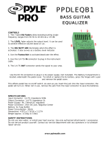
1. Connections
The diagram below shows a basic example of connec-
tions when using the D16 to record. Make the appropri-
ate connections for your system, substituting your own
equipment as necessary for the equipment shown here.
Be sure than the power is turned off while you are
making connections. If the power is on while con-
nections are being made, your speaker system may
be damaged, or other malfunctions may occur.
1 Connect the included AC/AC power supply.
Connect the AC/AC power supply to the AC/AC
power supply connector of the D16. Then plug the
other end into an AC outlet.
2 Connect your audio monitoring system.
Use RCA phono cables to connect a powered mon-
itor system (separately sold option: PM-15B ampli-
fied speakers) etc. to the [MONITOR OUT L/R]
jacks.
If you will be monitoring through headphones,
connect the 1/4" phone plug of your headphones
to the [PHONES] jack.
The audio signal that is output from the [MONI-
TOR OUT L/R] jacks and the [PHONE] jack is set
in the [SOLO/MONITOR] “Monitor” tab page.
(→p.84)
3 Connect your input devices.
Connecting audio devices to
the D16, and turning the
power on
PS-1
pedal switch
EXP-2
expression pedal
PHONES
FOOT SWITCH
EXPRESSION
PEDAL
to the AC outlet
Master recorder (Digital: DAT, MD, etc.)
Keyboard
Tone module
Guitar
Mic
Headphones
Effect processor
CD, DAT, MD etc.
Master recorder (Analog: cassette tape recorder, etc.)
Power supply connection
You must use the
included AC/AC power
supply
AC/AC power
supply connector
Powered monitors etc.
Hard disk drive, CD-R/RW drive
removable disk drive (MO, zip, jaz etc.)
MIDI
sequencer
D16
OUTPUT
INPUT 5–8
INPUT 5–8
AUX OUT
S/P DIF IN
DIGITAL IN
AUX IN
DIGITAL OUT
S/P DIF OUT
OUTPUT
L/R
INPUT
OUTPUT
GUITAR IN
INPUT
1–4
MIDI
IN/OUT
MIDI
OUT/IN
MONITOR
OUT L/R
MASTER
OUT L·R
SCSI
SCSI

12
Connections for recording analog sources
• Guitar, bass guitar ↔ [GUITAR IN] jack
• Mic (XLR) ↔ [INPUT 1], [INPUT 2] jacks
• Synthesizer etc. ↔ [INPUT 1]–[INPUT 8] jacks
A guitar or bass guitar that is being sent
through a compact effect device can be con-
nected to [INPUT 1]–[INPUT 8].
When inputting in stereo, you should select
two adjacent inputs (1–2, 3–4, 5–6, 7–8) so that
track editing can be performed more effi-
ciently.
If you are recording from a connected mic, locate
the mic at a sufficient distance from the D16 so that
it does not pick up noise.
For more input examples, and details on sending
the input audio to mixer channels and auditioning
input signals, refer to p.16.
Connections for recording digital sources
• Optical digital (S/P DIF) output of a digital out-
put device such as CD or MD ↔ [S/P DIF] con-
nector of the D16 (use an optical digital cable for
connection)
For more input examples, and details on sending
the input audio to mixer channels and auditioning
input signals, refer to p.18.
4 Make other connections.
Connections for mixdown
Make connections to the recording device (DAT,
MD, cassette tape recorder etc.) to which the song
you created on the D16 will be mixed down.
• Optical digital (S/P DIF) input of a digital
recording device such as DAT or MD ↔ [S/P
DIF OUT] of the D16
• AUX IN inputs of an analog recording device
such as a cassette tape recorder ↔ [MASTER
OUT L/R] jacks of the D16
Connections when using external effects
If you wish to apply an external effect to the signal
from [AUX OUT] send output, use the [INPUT 1]–
[INPUT 8] jacks to receive the return signal(s).
In this case, you can choose whether the signal(s)
will be returned to the mixer channel(s) in the
same way as a conventional input, or sent directly
to the master bus. (→p.75)
Connections when using a foot switch to perform
manual punch recording, or playback/stop etc.
Connect the pedal switch (separately sold option:
PS-1) to the [FOOT SWITCH] jack.
Connections when using a foot pedal to control
effects
Connect the expression pedal (separately sold
option: EXP-2, XVP-10) to the [EXPRESSION
PEDAL] connector.
Do not connect a volume pedal, since it will
not function correctly.
Connections when controlling effects or switching
scenes from an external MIDI device
MIDI OUT connector of the external MIDI device
↔ [MIDI IN] connector of the D16. (→p.47)
Connections when synchronizing the D16 with a
MIDI sequencer etc.
MIDI IN connector of the sequencer etc. ↔ [MIDI
OUT] connector of the D16 (use a MIDI cable for
connections)
If you will be using MMC, connect the MIDI OUT
connector of the sequencer etc. ↔ [MIDI IN] con-
nector of the D16. (→p.47)
Connections when producing an audio CD on a CD-
R/RW drive
• SCSI connector of the CD-R/RW drive ↔ [SCSI]
connector of the D16 (use a SCSI cable to make
connections). (→p.48)
Connections when saving or backing up data on an
external hard disk or removable disk
SCSI connector of the external SCSI device ↔
[SCSI] connector of the D16 (use a SCSI cable to
make connections). (→p.48)
2. Turning the power on/off
Turning the power on
Use the following procedure to turn on the power of
the D16 and of the devices connected to it.
Before turning the power on, set the vol-
ume controls of all devices to the minimum
position, and turn on the power switches
beginning with the devices that are earliest
(first) in the audio signal chain.
1 Lower the D16’s [MASTER] fader to the
–∞ position. Then turn the volumes of the
external devices to the minimum posi-
tions.
2 Turn on the power of the external input devices
(keyboards etc.) that send audio signals to the
D16.
If an external drive is connected, turn on the
power of the external drive.
3 Press the [POWER] key of the D16 to turn on the
power.
The LCD screen will show the opening message,
and then the [SONG] “SelSong” tab page will
appear.
The song that had been selected when the power
was last turned off will be selected.
4 Turn on the power of the devices to which audio
signals are being sent from the D16, such as your
monitor system or MD recorder.

13
Basic operation
Makin
g
connections
,
Turning the power off
When you are finished playing or recording a song,
turn off the power. Use the following procedure to turn
off the power of the D16 and of the connected devices.
Before turning off the power, turn the volume of all
devices down to the minimum position, and turn
off the power switches beginning with the devices
that are at the end of the audio signal chain.
Never disconnect the AC/AC power supply until
the power is completely off. Data may be
destroyed if you do so.
The audio that is recorded on the D16 and the
mixer settings etc. are saved automatically when
you select or change songs, or when you turn off
the power. However, effect settings that you edit
will be lost unless you save them.
1 If you wish to keep any effect settings that you
edited, save them. (→p.33)
2 Lower the [MASTER] fader of the D16 to the –∞
position. Then turn the volumes of all connected
external devices to the minimum position.
3 Turn off the power of devices to which the D16 is
sending audio, such as your monitor system or
MD recorder.
4 Press and hold down the [POWER] key of the
D16 to turn off the power.
When you press the [POWER] key, a message will
ask you for confirmation, so press the “YES” but-
ton.
5 If an external drive is connected, turn off the
power of the external drive.
6 Turn off the power of external input devices such
as a keyboard etc. that is sending audio to the
D16.
When shipped from the factory, the D16 contains sev-
eral demo songs. Here’s how to listen to these demo
songs.
1 Set the [CHANNEL] faders of the D16 to
the 0 position, and the [MASTER] fader to
–∞.
2 Select the song that you wish to play.
For details on selecting a song, refer to “3.
Selecting an existing song” (→p.14).
3 Make the [TRACK STATUS] key LED of
each track light green.
If any are lit with a different color, or are dark,
press the key to select green (PLAY).
4 Press the [PLAY] key to begin playback.
5 Gradually raise the [MASTER] fader to adjust the
volume level.
While the song plays, you can try adjusting the
[CHANNEL] faders, [PAN] knobs, EQ, the send
amount to the master effects, or selecting different
programs for the insert effects or master effects to
hear the result.
6 When the demo song finishes playing, press the
[STOP] key to stop playback.
Listening to the demo songs

14
Step 2. Creating or selecting a song
In order to record a new song, you must first create a
new song on the D16. Here’s how to create a new song,
assign a name to the song, and select a song.
1. Creating a new song
1 Select the [SONG] “SelSong” tab page.
Press the [SONG] key, and then the “SelSong” tab.
2 Press the “New” button.
3 Select the number of bits/tracks for the song that
will be created, and the mixer settings. (→p.59)
4 Press the “OK” button.
A song named “NewSong” will be created for the
song number that follows the last existing song.
To delete a song, refer to p.61.
2. Naming a song
We recommend that you assign a name to your new
song, to distinguish it from other songs.
If you wish to change the name of a song, you must
first select that song (→“3. Selecting an existing song”).
1 Select the [SONG] “SelSong” tab page.
Press the [SONG] key, and then the “SelSong” tab.
2 Press the “Rename” button.
3 Change the name of the song.
Use the “ ” “ ” buttons to move the cursor in the
song name (alphabetical characters) to the charac-
ters that you wish to change, and rotate the
[VALUE] dial to select the desired characters.
The buttons in the LCD screen have the following
function.
4 If you are satisfied with the name that you input,
press the “OK” button. If you decide not to
change the name, press the “Cancel” button.
3. Selecting an existing song
Selecting (creating) a new song is different than select-
ing an existing song. Here’s how to select an existing
song. (For a new song, refer to “1. Creating a new
song.”)
There are three ways to select an existing song.
[STOP] key + [FF] key, [STOP] key + [REW]
key
Use this method to select the previous or next num-
bered song in the same drive.
• To select the next-numbered song, hold down the
[STOP] key and press the [FF] key.
• To select the previous-numbered song, hold down
the [STOP] key and press the [REW] key.
If you are at the beginning of the song (“000:00.000”
etc.), you will move to the previous-numbered song.
If you are in the middle of a song, pressing the above
buttons once will move to the beginning of the song,
and pressing them once again will move to the
beginning of the previous-numbered song.
Creating or selecting a song
“Space” button: Select a blank (space).
“ClearAll” button: Erase the entire name.
“A../a..” button: Select the alphabetical charac-
ter “A.” Press once again to
select “a.”
“0…9” button: Select the numeral “0”
“Mark” button: Select the symbol
/