Intermatic EJ600 Series Installation And User Instructions Manual

Type
Installation And User Instructions Manual
7. Using diagram #2 remove and reconnect wires “B” and “C” to
the “COMMON” terminal of your remote switch, using the
supplied piece of jumper wire, if necessary.
NOTE: For new construction or to replace a dimmer switch, a
lighted switch, or a 3-way switch without screw terminals, a
single-pole switch should be used at the remote location, as
shown in diagram 3.
NOTE: If the building’s wiring colors don’t allow you to tell wire “A”
from “B”, just pick one of the two wires and connect as if it is wire “B”.
After the installation is complete, if the controlled light or device will
not turn on properly, simply reverse wires “A” and “B”. See Steps 11
through 14 below for how to check.
8. Gently tuck wires into the timer wall box leaving room for the timer.
9. Using screws provided, mount the switch timer into the wall
box, then install the wall plate.
10. Turn the power back on at the service panel.
11. Make sure the switch timer displays “MAN” mode. Perform the
test in Step 12 with the remote switch in each of its 2 positions.
12. Press the NEXT/ON/OFF button on the switch timer several
times. Each time that you push the NEXT/ON/OFF button, the
controlled light or device (the “load”) should turn on or off. If so
proceed to Step 14.
13. If the controlled light or device does not turn on or off, take one
of these actions.
- If the timer clicks but the load does not operate, re-check
your wiring and make sure the load is functional.
- If the timer clicks but the load only operates when the remote
switch is in one of its 2 positions, you need to turn off the
power at the service panel, then reverse wires “A” and “B”.
You can reverse wires “A” and “B” at the remote switch wall
box, or you can reverse wires “A” and “B” where they
connect to the red and blue wires of the switch timer. Then
turn power back on at the service panel and repeat Step 12.
14. Verify that the controlled load turns on or off each time that the
remote switch is operated. Your timer is ready to be set.
15. Proceed to Intro to Programming.
Installing the Switch Timer
1. Turn off power at the circuit breaker or fuse and verify that the
power is OFF before wiring.
2. Strip wire ends to 7/16”.
3. Make wire connections using the twist on
connectors provided.
4. Take one of these actions.
- If you have a single switch setup, then perform the
procedure “Installing the Timer with a Single Switch Setup”.
- If you have a 3-way switch setup, then perform the
procedure “Installing the Timer with a 3-way Switch Setup”.
Installing Switch Timer with a Single Switch Setup
1. Connect the LINE (Hot) wire from the wall to the black wire
from the switch timer with the twist
connectors provided.
2. Connect the LOAD wire from the wall to
the blue wire from the switch timer with
the twist connectors provided.
3. NOTE: Cap the RED wire, which is
not used in single-switch installations,
with a twist connector.
4. Connect the BARE COPPER wire
to the grounding screw in the box
If a plastic box, connect to ground as supplied.
5. Connect the NEUTRAL (usually White) wire from the wall to the
WHITE wire from the timer.
6. Gently tuck wires into the timer wall box leaving room for the timer.
7. Using screws provided, mount the switch timer into the wall
box, then install the wall plate.
8. Turn the power back on at the service panel.
9. Go to “Intro to Programming: Read Before you Begin.”
Installing the Timer with a 3-Way Switch Setup
NOTE:
The distance between switch timer and
remote switch must not exceed 100 feet.
The timer must be installed in the wall box
that contains the LINE and Neutral
wires. The remote switch must be
installed in the wall box that contains
the load wire (“WIRE C” in diagram 1).
1. Using diagram #1 below, identify the
LINE wire previously connected to the COMMON terminal of
the old 3-way main switch.
2. Connect the BLACK wire from switch timer to the LINE wire,
using a twist connector.
3. Connect the other two wires from the old switch to the BLUE
and RED wires from the switch timer.
4. Connect the BARE COPPER wire to the grounding screw in the
box. If a plastic box, connect to ground as supplied.
5. Connect the NEUTRAL (usually White) wire from the wall to the
WHITE wire from the timer.
6. Using diagram #1 below, identify and remove wire “C” from the
“COMMON” terminal of your existing remote switch.
7/16”
DIAGRAM 1:
TYPICAL
EXISTING
2-SWITCH
SETUP
LOAD
NEUTRAL
3-WAY
MAIN SWITCH
WIRE “A
“COMMON TERMINAL
LINE
3-WAY
REMOTE SWITCH
WIRE “B”
WIRE “C”
DIAGRAM 2:
2-SWITCH SETUP,
TIMER INSTALL
RE-USING EXISTING
REMOTE 3-WAY SWITCH
LOAD
NEUTRAL
WIRE “A
“COMMON” TERMINAL
LINE
3-WAY
REMOTE SWITCH
WIRE “B”
NOT USED
BLACK
TIMER
BLUE
RED
WIRE “C”
JUMPER
NEUTRAL
WHITE
DIAGRAM 3:
2-SWITCH SETUP,
TIMER INSTALL USING
NEW SINGLE-POLE
REMOTE SWITCH
LOAD
NEUTRAL
WIRE “A”
LINE
SINGLE-POLE
REMOTE SWITCH
WIRE “B”
BLACK
TIMER
BLUE
RED
WIRE “C”
JUMPER
NEUTRAL
WHITE
BLACK
BLUE
RED
(capped, not connected)
WHITE
DIGITAL ASTRONOMIC TIMER
MODEL EJ600 SERIES
Installation and User Instructions
RATINGS:
Single or multiple gang installations
Resistive 12 A
Tungsten 15 A (1800 W) Single Ganged, min 18 in
3
(295 cm
3
)
14 A, Single Ganged, minimum 12.5 in
3
(205 cm
3
)
12 A (1440 W) Multi-Ganged
Ballast 500 VA
Motor - 1/2 Hp
All ratings 120 VAC, 60 Hz.
A Neutral (WHITE) wire must be available to connect to timer.
BLACK
BLUE
RED
WHITE
WARNING
Risk of Fire or Electrical Shock
Disconnect power at the circuit breaker(s) or disconnect switch(es) before
installing or servicing.
Do NOT recharge, disassemble, heat above 100˚C (212˚F), crush, or incinerate the
non-replaceable Lithium battery. Keep out of reach of children.
Do NOT use timer to control devices that could have dangerous consequences due
to inaccurate timing such as sun lamps, sauna, heaters and crock pots.
Use #14 AWG wires, rated at least 90°C (194°F) - COPPER conductors ONLY.
Installation and/or wiring must be in accordance with national and local electrical
code requirements.
Intro to Programming: Read Before You Begin
As you press the buttons to program, it will be helpful to have
an overview of how they are organized. Press the MODE
button to rotate through the timer’s modes: CALendar, CLocK,
ProGraM, AUTO, AUTO RANDom, and MANual.
Within each mode, menus “loop”, so they repeat when you get
to the end.
You must set the CALendar and CLocK before programming
ON/OFF times.
If the timer is left idle for ve minutes, the programmed settings
are automatically saved.
NOTE: See section “Selecting Auto, Auto Random or Manual Opera-
tion” for description of each mode.
Clear Existing Programming
Before you program the timer, be sure to perform these instructions.
1. Open the control door.
2. Simultaneously press and hold RESET and NEXT ON/OFF
buttons.
3. Release RESET. The screen initializes, then ashes “12:00 AM”
in MANual mode.
4. Release NEXT ON/OFF. All previous settings are deleted.
Set the Calendar Information
In order for the timer to automatically adjust for seasonal changes in
sunrise and sunset and adjust for Daylight Saving Time, the CAL-
ENDAR must be set correctly. Follow this procedure to set Calendar
Info.
NOTE: If you go too far, Press the button to scroll back around. For
the year, you can also press the YEAR+ button to scroll through the
years.
1. Press MODE to display CAL and the year. The time screen
alternately displays YEAR and a ashing
number (Fig. 1).
2. Press YEAR+ or YEAR- as necessary to scroll
to the correct year.
3. Press NEXT ON/OFF. The screen alternately
displays dATE and a dashed line or ashing
number. (Fig. 2).
4. Press M+ to scroll to the correct month (Fig. 3).
5. Press DAY/DST to scroll to the correct date
(Fig. 3). The calculated day of the week
appears beneath the DATE.
6. Press NEXT ON/OFF to set Daylight Saving
Time (dST). The display ashes between dST
and AUTO (Fig.4).
7. Press DAY/DST to select AUTO (dST on) or
MAn (dST off).
Note: - If your area uses dST, select AUTO (Fig. 5).
- If your area does not use dST, select MAN.
8. Press NEXT ON/OFF to save the DST setting.
The screen alternately displays ZONE and
CENTr (Fig. 5)`.
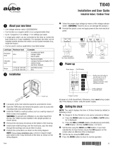
9. Press ZONE+ as needed to select a zone,
(SOUTh, NORTh, and CENTr). Use the map
(Fig. 7) to determine your zone.
NOTE: This feature tracks changes in
sunrise and sunset times.
10. Press NEXT ON/OFF. The display alternates
between SUNUp and an AM time (Fig. 8).
11. Take one of these actions:
- If you DO NOT want to set exact Sunup and Sunset times:
Go to “Set Time of Day”.
- If you want to set exact Sunup and Sunset times:
Go to step 12.
12. Press HOUR + as necessary to set the
correct SUNUp hour (Fig. 9).
Note: The smaller letter “d” indicates
Daylight Saving Time is in effect.
13. Press M+ to scroll to the desired minute.
14. Press NEXT ON/OFF to advance to setting
exact SNSEt time (Fig. 10).
15. Press HOUR + as necessary to set the correct
SNSEt hour.
16. Press M+ as necessary to set the correct SNSEt minute.
Fig. 8
Fig. 7
South
North
Center
North
Center
South
Set Time of Day
1. If you have not already done so, press MODE
to scroll to CLK (clock) and a time. The rst
time, 12:00 AM ashes (Fig. 11).
2. Press HOUR + to scroll to desired hour.
3. Press M+ to scroll to the desired minute.
NOTE: Make sure AM or PM is correct. Time and Date are
now set.
Set an ON/OFF Program at Specific Times
1. Press MODE to scroll to the PGM ON screen.
The display shows dashes if no time was set
(Fig. 12) or shows a time if previously set (Fig 13).
2. Press DAY/DST. The screen displays a time
and days of the week.
3. Press DAY/DST again to scroll to the desired
day(s) that you want the ON program to operate.
(Fig. 13). If you need to skip this ON program,
scroll to dashes (Fig. 12) and proceed to step 6.
See choices below:
- everyday
- weekdays only (Fig. 13)
- weekends only
- a specic day
NOTE: If you go too far, keep pressing
DAY/DST to loop back to the desired choice.
4. Press HOUR+ to scroll to the hour desired to
activate the load.(Fig. 14).
Note: Make sure AM or PM is correct.
5. Press M+ to scroll to the desired minute to
activate the load (Fig. 14).
6. Press NEXT ON/OFF to scroll to the PGM
OFF screen (Fig. 15).
7. Press DAY/DST. The screen displays a time
and some days of the week. (Fig. 16).
8. Press DAY/DST to scroll to the desired day(s)
you want this OFF program to operate.
(Fig. 16). If you need to skip this OFF program,
scroll to dashes (Fig. 15) and proceed to step 11.
9. Press HOUR+ to scroll to the hour when you want the load to
turn off. (Fig. 17).
NOTE: Make sure AM or PM is correct.
10. Press M+ to scroll to the minute when you want the load to
turn off (Fig. 17).
11. Take one of these actions:
- If all the required programs are set, press MODE to exit.
- If another program needs to be set, press NEXT ON/OFF
and repeat steps 2 through 10.
Set an ON/OFF Program for Sunrise/Sunset
1. Press MODE to scroll to the PGM ON screen.
Display shows dashes 1st time (Fig. 18) or
shows the screen of Fig. 19 or 20 if previously
set.
2. Press DAY/DST. The screen displays a time
and days of the week. (Fig. 19 or 20).
3. Pressing DAY/DST to scroll to SNST ON
screen (Fig. 20).
Pressing DAY/DST to select the day(s) you
want this SUNSET ON program to operate.
(Fig. 20). See below for a list of choices:
- everyday (MON - SUN)
- weekdays only (Fig. 19) MON - FRI)
- weekends only (SAT - SUN)
- a specic day of week
NOTE: If you go too far, Press DAY/DST to
scroll around to the desired setting.
If you need to skip this SUNSET ON program,
scroll to dashes (Fig. 18) and proceed to step 4.
4. Press NEXT ON/OFF to scroll to PGM OFF
screen. (Fig. 21, 22, or 23).
5. Press DAY/DST to scroll to SNUP OFF screen (Fig, 23).
6. Press DAY/DST to select the day(s) when you
want this SUNUP OFF program to operate. (Fig. 23). If you
need to skip this SUNUP OFF program scroll to dashes (Fig.21)
and proceed to step 7.
-2-
7. Take one of these actions:
- If all the required programs are set, press MODE to exit and
go to Selecting AUTO, AUTO/RANDom, or MANual
Operation.
- If another SUNSET or SUNUP program needs to be set,
press NEXT ON/OFF and repeat steps 2 through 6. The
program number next to “ON” or “OFF” will increase to help
you keep track of multiple programs.
- Go to Setting Sunset ON/Specific Time OFF.
Setting Sunset ON/Specific Time OFF
NOTE: Sunset ON / Specific Time OFF is the most common setting
for the switch timer. As a convenience, here is the full step by step.
1. Press MODE to scroll to PGM On screen
(Fig. 24, 25 or 26).
2. Press NEXT ON/OFF to scroll to a PGM ON
screen that has a dashed line for time
(Fig. 24).
3. Press DAY/DST to scroll to SNST (Fig. 26).
4. Press DAY/DST to select the days you want
the program to activate.
See the choices below:
- everyday (MON - SUN)
- weekdays only (MON - FRI)
- weekends only (SAT - SUN)
- a specic day of the week
NOTE: If you go too far, Press DAY/DST to scroll around to the
desired command.
5. Press NEXT ON/OFF to scroll to a PGM OFF
screen that has dashed lines (Fig. 27).
6. Press DAY/DST. A time and some days will
be displayed (Fig. 28).
7. Press DAY/DST to select the day(s) on which
you want the OFF program to operate. (Fig. 28).
NOTE: Because you are setting a specific OFF
time to operate in conjunction with a SUNSET
ON program that you already programmed in
step 4, choose the same day(s) as selected in
step 4 above.
8. Press HOUR+ to set the hour you want the program to turn
OFF.
9. Press M+ to set the minute you want the
program to turn OFF (Fig. 29).
NOTE: Make sure AM or PM is correct.
10. Take one of these actions.:
- If all the required programs are set, press MODE to exit.
- If another program needs to be set, repeat steps 2 through 9.
To Review or Revise Program Settings
1. Press MODE to scroll to PGM screen.
2. Press NEXT ON/OFF repeatedly to view the programs
(ON 1-7 and OFF 1-7). Dashes indicate that program is
skipped.
3. Repeat the programming steps above to make any desired
changes.
4. Press MODE to select AUTO, AUTO RANDom or MANual
mode as described below.
Selecting AUTO, AUTO RANDom, or MANual
Operation
After the timer programming is complete, select the controller mode.
1. Open the timer front cover.
2. Press MODE to select the desired MODE. Review the choices
below.
AUTO - uses the timer settings you have programmed
AUTO RANDom - gives your home a “lived-in” look by varying
your settings by a random amount of + 20 minutes or so.
MANual - maintains your settings but operates the timer like
a standard ON/OFF switch. Press on the door of the timer for
ON, press again for OFF.
3. Close the timer door and then press the door.
Note: Once the door is closed it operates as an ON/OFF switch.
Battery Memory Backup
Your timer contains a built-in, non-replaceable, rechargeable battery
to maintain the date and time of day information for at least 4 con-
secutive days of AC power interruption. All other user settings are
maintained indenitely without AC power. The built-in battery will fully
charge within a day of connection to AC power. After an extended
power outage, if the display is ashing “12:00 AM”, you will need to
re-enter the CALENDAR and TIME of DAY information.
Manual Override
To override a program (ON/OFF time) until the next scheduled time:
Press the control door (over the programming buttons), or
open the control door and press NEXT ON/OFF.
-3-
LIMITED ONE-YEAR WARRANTY
If within the warranty period specified, this product fails due to a defect in material or workmanship, Intermatic Incorporated will repair or replace it, at its sole option, free of charge.
This warranty is extended to the original household purchaser only and is not transferable. This warranty does not apply to: (a) damage to units caused by accident, dropping or abuse
in handling, acts of God or any negligent use; (b) units which have been subject to unauthorized repair, opened, taken apart or otherwise modified; (c) units not used in accordance with
instructions; (d) damages exceeding the cost of the product; (e) sealed lamps and/or lamp bulbs, LED’s and batteries; (f) the finish on any portion of the product, such as surface and/or
weathering, as this is considered normal wear and tear; (g) transit damage, initial installation costs, removal costs, or reinstallation costs.
INTERMATIC INCORPORATED WILL NOT BE LIABLE FOR INCIDENTAL OR CONSEQUENTIAL DAMAGES. SOME STATES DO NOT ALLOW THE EXCLUSION OR LIMITATION OF INCIDENTAL OR
CONSEQUENTIAL DAMAGES, SO THE ABOVE LIMITATION OR EXCLUSION MAY NOT APPLY TO YOU. THIS WARRANTY IS IN LIEU OF ALL OTHER EXPRESS OR IMPLIED WARRANTIES. ALL
IMPLIED WARRANTIES, INCLUDING THE WARRANTY OF MERCHANTABILITY AND THE WARRANTY OF FITNESS FOR A PARTICULAR PURPOSE, ARE HEREBY MODIFIED TO EXIST ONLY
AS CONTAINED IN THIS LIMITED WARRANTY, AND SHALL BE OF THE SAME DURATION AS THE WARRANTY PERIOD STATED ABOVE. SOME STATES DO NOT ALLOW LIMITATIONS ON THE
DURATION OF AN IMPLIED WARRANTY, SO THE ABOVE LIMITATION MAY NOT APPLY TO YOU.
This warranty service is available by either (a) returning the product to the dealer from whom the unit was purchased or (b) completing a warranty claim online at
www.intermatic.com. This warranty is made by: Intermatic Incorporated, Customer Service 7777 Winn Rd., Spring Grove, Illinois 60081-9698. For warranty service go to:
http://www.Intermatic.com or call 815-675-7000.
INTERMATIC INCORPORATED, 7777 Winn Road
SPRING GROVE, ILLINOIS 60081-9698
www.intermatic.com
Troubleshooting Guide
Observed Problem Possible Cause Solution
Timer is blank until a button is pushed and No power (fuse or circuit breaker blown), loose wiring Make sure fuse is not blown and circuit
display changes between ON and OFF when connection or no load / burned out bulbs. breaker is on.
pressing door, but light stays OFF or flickers. Replace fuse if necessary.
Timer does not switch but display is normal. Timer not in AUTO, AUTO RAND(om), or MAN(ual) mode. Press MODE to select the desired operating
mode.
Timer works manually but does not follow Timer not in AUTO or AUTO RAND(om) mode. Press MODE to select AUTO RAND.
scheduled program.
Timer will not enter the AUTO or AUTO RAND Time of day and/or switching times are not programmed. Make sure time of day and at least one scheduled
modes when MODE is pressed. activity are programmed. See Set an ON/OFF Program.
Timer switches at incorrect times or skips Programmed schedule(s) are incorrect. Review ALL 7 ON/OFF switching time pairs by
some switching times. repeatedly pushing NEXT ON/OFF while in PGM
mode and revise as necessary.
Timer is in AUTO RAND(om) mode (varies switching times Press MODE to select AUTO mode.
up to + 15 minutes).
When using a combination of Astronomic and There are conflicting Astronomic and specific switching time 1. Complete the steps under “Setting the
specific switching times, the timer switches at settings. Your timer automatically skips any conflicting ON Calendar”.
unexpected times or does not switch when EVENTS as summer approaches to prevent unwanted opera- 2. Temporarily change your timer’s calendar
expected. tion of lights. See the next column if you wish to identify and setting to June 21st.
remove conflicting settings. 3. Review the SUNUP and SNST times by pressing
NEXT/ON/OFF.
4. Make sure your specific ON or OFF time set-
tings will not interfere with these Astronomic
switching times.
5. Be sure to change the date when you are done.
Load state does not match programmed state The timer does not “catch up” to the programmed load state. After entering your schedule or the time, then
immediately after programming the time or Instead, the load will remain in its current state prior to enter- returning to the AUTO modes, push NEXT/ON/OFF
schedule. ing the PGM mode. The timer will then begin following the to change the load state if necessary.
scheduled program at the next contrary ON/OFF time.
Load only operates when the remote (3-way) Remote switch is wired incorrectly. Verify the wiring is installed correctly,
switch is in one position or timer ignores the including the jumper.
remote switch.
Timer ignores remote (3-way) switch even Excessive length of wire (greater than 100 feet) or buried Eliminate condition by replacing the buried cable
though it is wired correctly. wiring to the remote switch. or doing without the remote switch. Consult
factory for other options.
Remote switch is defective or worn out. Replace the remote switch.
Load turns off immediately after being turned on. Remote switch or timer wired incorrectly, excessive length If the problem persists with the timer’s red wire
of wire (greater than 100 feet) or buried wiring to remote disconnected or with a remote switch temporarily
switch, or defective timer. connected right at the timer, replace the defective
timer. Otherwise try the above remedies.
-4-
  • Page 1 1
  • Page 2 2
  • Page 3 3
  • Page 4 4
  • Page 5 5
  • Page 6 6
  • Page 7 7
  • Page 8 8
  • Page 9 9
  • Page 10 10
  • Page 11 11
  • Page 12 12

Intermatic EJ600 Series Installation And User Instructions Manual

Type
Installation And User Instructions Manual

Ask a question and I''ll find the answer in the document

Finding information in a document is now easier with AI

in other languages