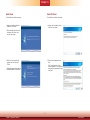
DFI WM343-KD Owner's manual
- Category
- Motherboards
- Type
- Owner's manual
This manual is also suitable for

1
Chapter 1 Introduction www.d.com
WM343-KD330/KD331
Desktop Box PC
User’s Manual
A-499-M-2008

2
Chapter 1 Introduction www.d.com
Copyright
This publication contains information that is protected by copyright. No part of it may be re-
produced in any form or by any means or used to make any transformation/adaptation without
the prior written permission from the copyright holders.
This publication is provided for informational purposes only. The manufacturer makes no
representations or warranties with respect to the contents or use of this manual and specifi-
cally disclaims any express or implied warranties of merchantability or fitness for any particu-
lar purpose. The user will assume the entire risk of the use or the results of the use of this
document. Further, the manufacturer reserves the right to revise this publication and make
changes to its contents at any time, without obligation to notify any person or entity of such
revisions or changes.
Changes after the publication’s first release will be based on the product’s revision. The web-
site will always provide the most updated information.
© 2018. All Rights Reserved.
Trademarks
Product names or trademarks appearing in this manual are for identification purpose only and
are the properties of the respective owners.
FCC and DOC Statement on Class A
This equipment has been tested and found to comply with the limits for a Class A digital
device, pursuant to Part 15 of the FCC rules. These limits are designed to provide reason-
able protection against harmful interference when the equipment is operated in a residential
installation. This equipment generates, uses and can radiate radio frequency energy and, if not
installed and used in accordance with the instruction manual, may cause harmful interference
to radio communications. However, there is no guarantee that interference will not occur in a
particular installation. If this equipment does cause harmful interference to radio or television
reception, which can be determined by turning the equipment off and on, the user is encour-
aged to try to correct the interference by one or more of the following measures:
• Reorient or relocate the receiving antenna.
• Increase the separation between the equipment and the receiver.
• Connect the equipment into an outlet on a circuit different from that to which the receiver
is connected.
• Consult the dealer or an experienced radio TV technician for help.
Notice:
1. The changes or modifications not expressly approved by the party responsible for compli-
ance could void the user’s authority to operate the equipment.
2. Shielded interface cables must be used in order to comply with the emission limits.

3
Chapter 1 Introduction www.d.com
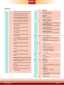
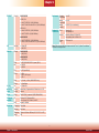
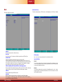
Table of Contents
Copyright ���������������������������������������������������������������������� 2
Trademarks ������������������������������������������������������������������ 2
FCC and DOC Statement on Class A ���������������������������� 2
About this Manual �������������������������������������������������������� 4
Warranty ��������������������������������������������������������������������� 4
Static Electricity Precautions ��������������������������������������� 4
Safety Measures ����������������������������������������������������������� 4
Safety Precautions ������������������������������������������������������� 5
About the Package ������������������������������������������������������� 5
Before Using the System ��������������������������������������������� 5
Chapter 1 - Introduction ���������������������������������������������� 6
Chapter 2 - Getting Started ��������������������������������������� 12
Chapter 3 - Installing Devices ����������������������������������� 13
Chapter 4 - Jumper Settings ������������������������������������ 22
Clear CMOS ...........................................................................22
Serial Port RS232/422/485 Select ...........................................23
Serial Port Power Select .........................................................25
Mini PCIe/mSATA Signal Select (for KD330-Q170 only) ............ 26
Chapter 5 - Ports and Connectors ���������������������������� 27
Rear Panel I/O Ports ..............................................................27
PS/2 Keyboard/Mouse Port .......................................................................... 27
COM (Serial) Ports ...................................................................................... 28
Graphics Interfaces ..................................................................................... 28
RJ45 LAN Ports ........................................................................................... 29
USB Ports ................................................................................................... 29
Audio ........................................................................................................ 30
I/O Connectors ...................................................................... 30
Front Audio Connector (WM343-KD331 only) ............................................... 30
S/PDIF Connector ....................................................................................... 31
Digital I/O and Power Connector ................................................................. 32
SATA (Serial ATA) Connectors ...................................................................... 33
COM (Serial) Ports ...................................................................................... 34
USB Ports ................................................................................................... 35
Cooling Fan Connectors............................................................................... 36
Chassis Intrusion Connector ....................................................................... 37
LPC Connector ............................................................................................ 38
Power Connectors ....................................................................................... 39
SMBus Connector ...................................................................................... 40
Front Panel Connector ................................................................................ 41
Expansion Slots .......................................................................................... 42
Standby Power LED .................................................................................... 43
Battery ....................................................................................................... 43
LAN LED ................................................................................................... 44
Chapter 6 - Mounting Options ����������������������������������� 45
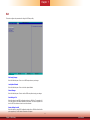
Chapter 7 - BIOS Setup ��������������������������������������������� 47
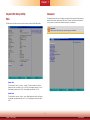
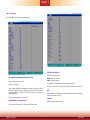
Overview ..............................................................................47
Insyde BIOS Setup Utility ....................................................... 48
Main .......................................................................................................... 48
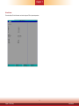
Advanced .................................................................................................. 48
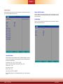
UEFI Device Manager ................................................................................. 55
Security ...................................................................................................... 60
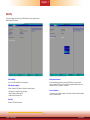
Boot........................................................................................................... 61
Exit ............................................................................................................ 62
Updating the BIOS .................................................................63
Notice: BIOS SPI ROM ...........................................................63
Chapter 8 - Supported Software �������������������������������� 64
Chapter 9 - RAID ������������������������������������������������������ 72
Chapter 10 - Intel AMT Settings ������������������������������� 76

4
Chapter 1 Introduction www.d.com
About this Manual
An electronic file of this manual can be obtained from the DFI website at www.dfi.com.
To download the user’s manual from our website, please go to “Support” > “Download Center.”
On the Download Center page, select your product or type the model name and click “Search”
to find all technical documents including the user’s manual for a specific product.
Warranty
1. Warranty does not cover damages or failures that arised from misuse of the product,
inability to use the product, unauthorized replacement or alteration of components and
product specifications.
2. The warranty is void if the product has been subjected to physical abuse, improper instal-
lation, modification, accidents or unauthorized repair of the product.
3. Unless otherwise instructed in this user’s manual, the user may not, under any circum-
stances, attempt to perform service, adjustments or repairs on the product, whether in or
out of warranty. It must be returned to the purchase point, factory or authorized service
agency for all such work.
4. We will not be liable for any indirect, special, incidental or consequential damages to the
product that has been modified or altered.
Static Electricity Precautions
It is quite easy to inadvertently damage your PC, system board, components or devices even
before installing them in your system unit. Static electrical discharge can damage computer
components without causing any signs of physical damage. You must take extra care in han-
dling them to ensure against electrostatic build-up.
1. To prevent electrostatic build-up, leave the system board in its anti-static bag until you are
ready to install it.
2. Wear an antistatic wrist strap.
3. Do all preparation work on a static-free surface.
4. Hold the device only by its edges. Be careful not to touch any of the components, contacts
or connections.
5. Avoid touching the pins or contacts on all modules and connectors. Hold modules or con
nectors by their ends.
Safety Measures
To avoid damage to the system:
• Use the correct AC input voltage range.
To reduce the risk of electric shock:
• Unplug the power cord before removing the system chassis cover for installation or servic-
ing. After installation or servicing, cover the system chassis before plugging the power cord.
Battery:
• Danger of explosion if battery incorrectly replaced.
• Replace only with the same or equivalent type recommend by the manufacturer.
• Dispose of used batteries according to local ordinance.
Important:
Electrostatic discharge (ESD) can damage your processor, disk drive and other com-
ponents. Perform the upgrade instruction procedures described at an ESD worksta-
tion only. If such a station is not available, you can provide some ESD protection by
wearing an antistatic wrist strap and attaching it to a metal part of the system chas-
sis. If a wrist strap is unavailable, establish and maintain contact with the system
chassis throughout any procedures requiring ESD protection.

5
Chapter 1 Introduction www.d.com
About the Package
The package contains the following items. If any of these items are missing or damaged,
please contact your dealer or sales representative for assistance.
• 1 WM343-KD330 or WM343-KD331 System Unit
• 1 CPU cooler
• 1 SATA Data Cable (Length: 650mm)
• 4 HDD Screws
• 1 PSU Flex ATX 150W/250W/350W/400W/500W (250W Default)
• 1 System Fan
Optional Items
• Power Cord
• 3.5” HDD Tray Kit
The board and accessories in the package may not come similar to the information listed
above. This may differ in accordance to the sales region or models in which it was sold. For
more information about the standard package in your region, please contact your dealer or
sales representative.
Before Using the System
Before powering-on the system, prepare the basic system components.
If you are installing the system board in a new system, you will need at least the following
internal components.
• CPU and Memory module
• Storage devices such as hard disk drive, CD-ROM, etc.
You will also need external system peripherals you intend to use which will normally include at
least a keyboard, a mouse and a video display monitor.
Safety Precautions
• Use the correct DC input voltage range.
• Unplug the power cord before removing the system chassis cover for installation or servic-
ing. After installation or servicing, cover the system chassis before plugging the power cord.
• Danger of explosion if battery incorrectly replaced.
• Replace only with the same or equivalent type recommend by the manufacturer.
• Dispose of used batteries according to local ordinance.
• Keep this system away from humidity.
• Place the system on a stable surface. Dropping it or letting it fall may cause damage.
• The openings on the system are for air ventilation to protect the system from overheating.
DO NOT COVER THE OPENINGS.
• Place the power cord in such a way that it will not be stepped on. Do not place anything on
top of the power cord. Use a power cord that has been approved for use with the system
and that it matches the voltage and current marked on the system’s electrical range label.
• If the system will not be used for a long time, disconnect it from the power source to avoid
damage by transient overvoltage.
• If one of the following occurs, consult a service personnel:
- The power cord or plug is damaged.
- Liquid has penetrated the system.
- The system has been exposed to moisture.
- The system is not working properly.
- The system dropped or is damaged.
- The system has obvious signs of breakage.
• The unit uses a three-wire ground cable which is equipped with a third pin to ground the
unit and prevent electric shock. Do not defeat the purpose of this pin. If your outlet does
not support this kind of plug, contact your electrician to replace the outlet.
• Disconnect the system from the DC outlet before cleaning. Use a damp cloth. Do not use
liquid or spray detergents for cleaning.

6
Chapter 1 Introduction www.d.com
Chapter 1 - Introduction
Chapter 1
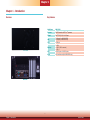
Overview
Key Features
Model Name WM343-KD
Processor
6th/7th Generation Intel
®
Core
TM
processors
Chipset
Intel
®
C236 / Q170 / H110 Chipset
LAN
2 LAN ports (for WM343-KD330)
4 LAN ports (for WM343-KD331)
COM
1 COM port
Displays
1 x VGA
1 x DVI-D (DVI-I connector)
1 x DP++
USB 4 USB 3.0 ports + 2 USB 2.0 ports
Audio
Mic-in and Line-out (for WM343-KD330 only)
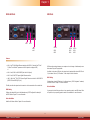
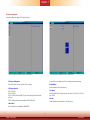
Front View
Rear View

7
Chapter 1 Introduction www.d.com
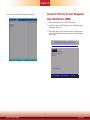
Specifications
Chapter 1
System Processor 6th Generation Intel
®
Core
TM
Processors (LGA 1151 Socket)
Intel
®
Xeon
®
Processor E3-1275 v5, Quad Core, 8M Cache,
3.6GHz (4.0GHz), 80W (available for KD331-C236 only)
Intel
®
Xeon
®
Processor E3-1225 v5, Quad Core, 6M Cache,
3.3GHz (3.7GHz), 80W (available for KD331-C236 only)
Intel
®
Xeon
®
Processor E3-1268L v5, Quad Core, 8M Cache,
2.4GHz (3.4GHz), 35W (available for KD331-C236 only)
Intel
®
Core™ i7-6700 Processor, Quad Core, 8M Cache,
3.4GHz (4.0GHz), 65W
Intel
®
Core™ i7-6700TE Processor, Quad Core, 8M Cache,
2.4GHz (3.4GHz), 35W
Intel
®
Core™ i5-6500 Processor, Quad Core, 6M Cache,
3.2GHz (3.6GHz), 65W
Intel
®
Core™ i5-6500TE Processor, Quad Core, 6M Cache,
2.3GHz (3.3GHz), 35W
Intel
®
Core™ i3-6100 Processor, Dual Core, 4M Cache, 65W
Intel
®
Core™ i3-6100TE Processor, Dual Core, 4M Cache,
2.7GHz, 35W
Intel
®
Pentium
®
Processor G4400, Dual Core, 3M Cache,
3.3GHz, 65W
Intel
®
Pentium
®
Processor G4400TE, Dual Core, 3M Cache,
2.9GHz, 35W
Intel
®
Celeron
®
Processor G3900, Dual Core, 2M Cache,
2.8GHz, 65W
Intel
®
Celeron
®
Processor G3900TE, Dual Core, 2M Cache,
2.6GHz, 35W
7th Generation Intel
®
Core
TM
Processors (LGA 1151 Socket)
Intel
®
Xeon
®
E3-1275 v6, Quad Core, 8M Cache, 3.8GHz (4.2GHz),
80W (available for KD331-C236 only)
Intel
®
Core™ i7-7700 Processor, Quad Core, 8M Cache, 3.6GHz
(4.2GHz), 65W
Intel
®
Core™ i5-7500 Processor, Quad Core, 6M Cache, 3.4GHz
(3.8GHz), 65W
Intel
®
Core™ i3-7101E Processor, Dual Core, 3M Cache, 3.9GHz , 65W
ECC memory Supported)
Chipset WM343-KD330
KD330-Q170: Intel
®
Q170 Chipset
KD330-H110: Intel
®
H110 Chipset
WM343-KD331
KD331-C236: Intel
®
C236 Chipset
KD331-Q170: Intel
®
Q170 Chipset
Memory WM343-KD331 (KD331-C236)
Four 288-pin ECC/Non-ECC DIMM up to 64GB, Dual Channel DDR4 2133/2400 MHz
WM343-KD331 (KD331-Q170)
Four 288-pin DIMM up to 64GB, Dual Channel DDR4 2133/2400 MHz
WM343-KD330 (KD330-Q170)
Four 288-pin DIMM up to 64GB, dual channel DDR4 2133/2400 MHz
WM343-KD330 (KD330-H110):
Two 288-pin DIMM up to 32GB, dual channel DDR4 2133/2400 MHz
Graphics Controller Intel
®
HD Gen 9 Graphics
Feature OpenGL 5.0, DirectX 12, OpenCL 2.1
HW Decode: AVC/H.264, MPEG2, VC1/WMV9, JPEG/MJPEG,
HEVC/H265, VP8, VP9
HW Encode: MPEG2, AVC/H264, JPEG, HEVC/H265, VP8, VP9
Display 1 x VGA
1 x DVI-D (DVI-I connector)
1 x DP++
VGA: resolution up to 1920x1200 @ 60Hz
DVI-I: resolution up to 1920x1200 @ 60Hz
DP++: resolution up to 4096x2304 @ 60Hz
Triple Display VGA + DVI-D + DP++
Storage External 1 or 2 x 3.5"/2.5" SATA 3.0 Drive Bays (1 x 3.5" SATA drive bay,
by default)
1 x 5.25" Optical Drive Bay
Expansion Interface WM343-KD330
1 x PCIe x16 (Gen 3)
1 x PCIe x4 (Gen 3)
2 x PCI
1 x Full-size Mini PCIe (USB/PCIe/mSATA, PCIe by default) (only
for KD330-Q170)
WM343-KD331
2 x PCIe x16 (1 x16 or 2 x8 signal) (Gen 3)
2 x PCIe x4 (Gen 3)
1 x M.2 Key M (2260/2280) (Intel
®
Optane™ memory support for
Intel
®
C236 Chipset only)
Audio Codec Realtek ALC888S-VD2-GR

8
Chapter 1 Introduction www.d.com
Environment Operating
Temperature
0 to 45°C
Storage
Temperature
0 to 60°C
Relative
Humidity
5 to 95% RH (non-condensing)
Standards &
Certications
Shock Operating: 3G
Non-operating: 5G
Vibration Operating: Random 5~500Hz 0.5G
Non-operating: Sine 10~500Hz 1.5G
Package
Drop
ISTA Project 1A
Chapter 1
ETHERNET Controller WM343-KD330
KD330-Q170:
1 x Intel
®
I211AT PCIe (10/100/1000Mbps)
1 x Intel
®
I219LM PCIe with iAMT11.0 (10/100/1000Mbps)*
KD330-H110:
1 x Intel
®
I211AT PCIe (10/100/1000Mbps)
1 x Intel
®
I219V PCIe (10/100/1000Mbps)
WM343-KD331
3 x Intel
®
I211AT PCIe (10/100/1000Mbps)
1 x Intel
®
I219LM PCIe with iAMT11.0 (10/100/1000Mbps)*
LED Indicators 1 x Power LED
1 x HDD LED
REAR I/O Ethernet WM343-KD330
2 x GbE (RJ-45)
WM343-KD331
4 x GbE (RJ-45)
Serial 1 x RS-232/422/485 (RS-232 w/ power) (DB-9)
USB 4 x USB 3.0
2 x USB 2.0
PS/2 1 x PS/2 (mini-DIN-6)
Display 1 x VGA
1 x DVI-I (DVI-D signal)
1 x DP++
Audio 1 x Line-out, 1 x Mic-in (WM343-KD330 only)
Buttons 1 x Power Button
Cooling Fan 1 x System Fan
WatchDog
Timer
Output &
Interval
System Reset, Programmable via Software from 1 to 255
Seconds
Power Supply Flex ATX 250W (or optional 150/250/350/400/500W)
OS Support
and BIOS
OS Windows 10 IoT Enterprise 64-bit
Linux: Ubuntu 15.10, Debian 8, CentOS 7
BIOS Insyde SPI 128Mbit
Mechanism Construction Sheet Metal
Mounting Wall Mount
Dimensions 349mm x 140.2mm x 290.9mm (13.74" x 5.52" x 11.45")
Weight TBD
Note: *SKUs with the Intel
®
H110 chipset or the Intel
®
Core™ i3, Celeron
®
and Pentium
®
processors do not support iAMT.

9
Chapter 1 Introduction www.d.com
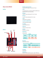
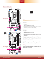
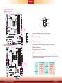
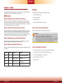
DVI-D (DVI-I connector)/DP++/VGA Port
Connects the DVI-D (DVI-I signal)/DP++/VGA connector of an LCD monitor.
COM Port
Connects serial devices. COM 1 can be selected among RS232, RS422 and RS485 as well as
between RS232 and RS232 with power via jumper settings.
USB 3�0 Ports
Connect USB 3.0 devices and devices based on USB 2.0 and 1.1/1.0 versions.
USB 2�0 Ports
Connect USB 2.0 devices and devices based on USB 1.1/1.0 versions.
LAN Ports
Connect the system to a local area network.
Line-out/Mic-in (for WM343-KD330 only)
Connects an external speaker and microphone.
PS/2 KB/Mouse
Connects a PS/2 keyboard and mouse.
Expansion slots
Provides PCIe or PCI expansion connectivity.
Power Button
Press to power on or off the system.
Status LED (Green)
Indicates system status.
HDD LED (Red)
Indicates the status of hard drives.
SATA Drive Bay
Inserts a SATA drive.
Optical Drive Bay
Inserts a DVD or CD-ROM. Note that this bay can also be an optional 3.5” SATA drive bay.
Chapter 1
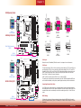
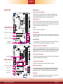
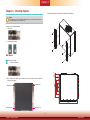
Getting to Know the WM343-KD
Front View
Status LED
ACPI state S0 Sleep S4, S5
LED Behavior
ON Blinking Off
HDD LED
HDD State
Disk access
activity
Disk drives present or not present
LED Behavior
Blinking Off
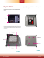
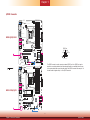
Rear View
Power Button
Optical
Drive Bay
SATA
Drive Bay
Expansion
Slots
USB 3.0 Ports
DVI-D
DP++
PS/2 Keyboard/Mouse
USB 2.0 Ports
COM
VGA
HDD LED (red)
Status LED (green)
LAN Ports
KD331: LAN 3 & LAN 4
KD330: Line-out & Mic-in

10
Chapter 1 Introduction www.d.com
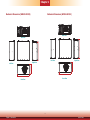
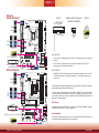
349
140.20
290.9
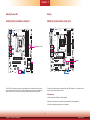
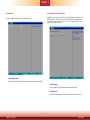
Mechanical Dimensions (WM343-KD330)
Chapter 1
349
140.20
290.9
Front View
Right View
Left View
Rear View
Mechanical Dimensions (WM343-KD331)
Front View
Right ViewLeft View
Rear View

11
Chapter 1 Introduction www.d.com
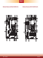
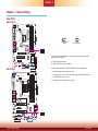
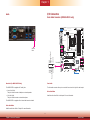
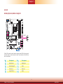
Chapter 1
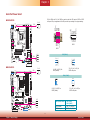
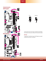
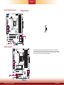
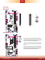
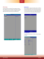
Motherboard Dimensions (KD330-Q170/KD330-H110)
10.16
0.00
22.86
154.94
227.33
205.33
233.68
150.29
75.29
94.79
130.79
46.94
154.94
29.22
20.32
45.72
203.20
160.23
227.33
180.23
209.55
0.00
45.72
47.29
26.97
34.29
165.82
90.81
6.65
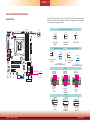
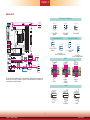
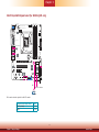
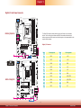
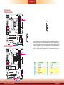
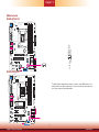
Motherboard Dimensions (KD331-C236/KD331-Q170)
46.94
154.94
10.16
0.00
22.86
154.94
227.33
233.68
150.29
75.29
94.79
130.79
20.32
45.72
203.20
90.81
165.82
209.55
0.00
47.29
26.97
198.98
173.73
135.39
105.13
84.63

12
Chapter 2 Getting Started www.d.com
Chapter 2 - Getting Started
Chapter 2
Preparing the System
Before you start using the system, you need the following items:
• SATA HDD/SSD
• Mini PCIe card
• M.2 card
• PCIe cards
• CPU
Installing Devices
The following devices can be installed in the system:
• DIMM
• Mini PCIe card
• M.2 card
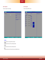
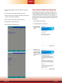
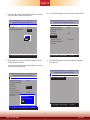
Configuring the BIOS
To get you started, you may need to change configurations such as the date, time and the
type of hard disk drive.
1. Power on the system.
2. After the memory test, the message “Press DEL to run setup” will appear on the screen.
Press the Delete key to enter the BIOS setup utility.
Installing an Operating System
Most operating system software can be installed using a DVD (and DVD burner) or bootable
USB drive.
Please refer to your operating system manual for instructions on installing an operating system.
Installing the Drivers
The system requires you to install drivers for some devices to operate properly. Refer to the
Supported Software chapter for instructions on installing the drivers.

www.d.com
13
Chapter 3 Installing Devices
Chapter 3
Chapter 3 - Installing Devices
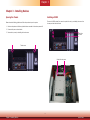
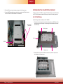
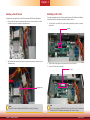
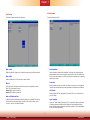
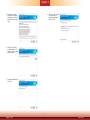
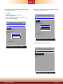
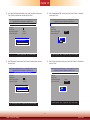
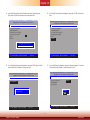
Opening the Chassis
Please observe the following guidelines and follow the procedure to open the system.
1. Make sure the system and all other peripheral devices connected to it have been powered off.
2. Disconnect all power cords and cables.
3. Remove the top cover by uninstalling the thumb screws.
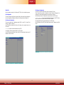
Installing a DIMM
To access the DIMM sockets, rst remove the optical drive tray by uninstalling the screws from
the rear panel and inside the chassis.
Thumb screw
Optical drive
tray screw
Optical drive tray screw

www.d.com
14
Chapter 3 Installing Devices
Chapter 3
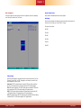
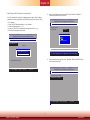
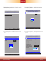
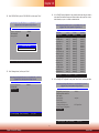
1. Align the notch on the DIMM with the tab in the DIMM socket.
2. Press down on the DIMM until the release tabs spring back to secure the DIMM in place.
The installed DIMM
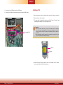
Installing a CPU
1.
Make sure the system and all other peripheral devices connected to it have been powered-off.
2. Disconnect all power cords and cables.
3. The system board is equipped with a surface mount LGA 1151 socket. This socket is exclu-
sively designed for installing a LGA 1151 packaged Intel CPU.
Important:
1. Before you proceed, make sure (1) the LGA 1151 socket comes with a protective
cap, (2) the cap is not damaged and (3) the socket’s contact pins are not bent. If
the cap is missing or the cap or contact pins are damaged, contact your dealer im-
mediately.
2. Keep the protective cap. RMA requests will be accepted and processed only if the
LGA 1151 socket comes with the protective cap.
4. Unlock the socket by pushing the load lever down, move it sideways until it is released
from the retention tab, and then lift the load lever up.
Protective
cap
Load lever

www.d.com
15
Chapter 3 Installing Devices
Chapter 3
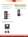
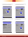
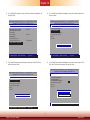
5. Remove the protective cap from the CPU socket. The cap is used to protect the CPU sock-
et against dust and harmful particles. Remove the protective cap only to install the CPU.
6. Insert the CPU into the socket. The gold triangular mark on the CPU must align with the
corner of the CPU socket as the photo shown below.
7. Unlock the socket by pushing the load lever down and moving it sideways until it is re-
leased from the retention tab and then lift the load lever up.
8. Insert the CPU into the socket. The gold triangular mark on the CPU must align with the
corner of the CPU socket as shown below. The CPU’s notch will at the same time fit into
the socket’s alignment key.
Alignment key
Gold triangular mark
Retention tab
Protective
cap
Load lever
Load plate
Important:
The CPU will fit in only one orientation and can easily be inserted without exerting
any force.
9. Close the load plate and push the load lever down to lock it under the retention tab. While
closing the load plate, slide the front edge of the load plate under the retention tab.
Retention knob

www.d.com
16
Chapter 3 Installing Devices
Chapter 3
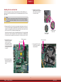
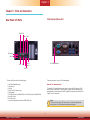
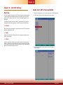
Installing the Fan and Heat Sink
The CPU must be kept cool by using a CPU fan with heat sink. Without sufficient air cir-
culation across the CPU and heat sink, the CPU will overheat damaging both the CPU and
system board.
1. Before you install the fan / heat sink, you must apply a thermal paste onto the top of
the CPU. The thermal paste is usually supplied when you purchase the fan / heat sink
assembly. Do not spread the paste all over the surface. When you later place the heat
sink on top of the CPU, the compound will disperse evenly.
Some heat sinks come with a patch of pre-applied thermal paste. Do not apply thermal
paste if the fan / heat sink already has a patch of thermal paste on its underside. Peel
the strip that covers the paste before you place the fan / heat sink on top of the CPU.
2. Place the heat sink on top
of the CPU. The 4 screw
around the heat sink,
which are used to secure
the heat sink onto the sys-
tem board, must match the
4 mounting holes around
the socket.
3. Orient the heat sink such
that the CPU fan’s cable is
nearest the CPU fan con-
nector.
Note:
A boxed Intel
®
processor already includes the CPU fan and heat sink assembly.
If your CPU was purchased separately, make sure to only use Intel
®
-certified fan
and heat sink.
Mounting hole
CPU fan connector
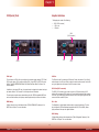
4. Rotate each screw that are
diagonally across the heat sink.
Perform the same procedure
for the other screws.
5. Connect the CPU fan’s cable
to the CPU fan connector on
the system board.
Heat sink
“Locked” position
of the screw
“Unlocked” position
of the screw
CPU fan connector

www.d.com
17
Chapter 3 Installing Devices
Chapter 3
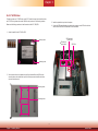
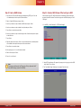
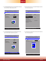
Installing a 3�5" or 2�5” SATA Drive
1. Remove the thumb screws that secure the HDD drive tray to the chassis and remove the
drive tray.
2. Secure the hard drive to the drive tray. Align the mounting holes on the SATA drive with the
mounting holes on the HDD drive tray. Use 4 mounting screws to install the hard drive onto
the HDD drive tray.
Thumb screw
Drive bay
Mounting screw
Mounting screw
3�5" SATA Drive
Use the same HDD drive tray to secure a 2.5" hard disk to the system. Refer to the pictures below
for the location of the mounting holes.
Mounting screw
Mounting screw
2�5" SATA Drive

www.d.com
18
Chapter 3 Installing Devices
Chapter 3
3. Slide the HDD drive tray back to the system and secure it with the thumb screws.
4. Connect the SATA data cable and power cable to the connectors on the SATA drive. And con
-
nect the other end of the SATA data cable on the motherboard.
SATA data and
power cable
SATA Port
Installing More Than One SATA Drive (Optional)
To install more than one 2.5" SATA drive, use the 5.25" optical drive tray. And to install more than
one 3.5" SATA drive, please order another HDD drive tray as shown in the following procedure.
Use the following procedure to install a second 3.5" HDD/SSD:
Drive bay
Mounting screw
Mounting screw
1. Secure the hard drive to the drive tray. Align the mounting holes on the SATA drive with the
mounting holes on the HDD drive tray. Use 4 mounting screws to install the hard drive onto
the HDD drive tray.
2. Slide the HDD drive tray with the installed hard drive into the optical drive bay and secure
the installation with the thumb screws.
For 3�5" SATA Drives

www.d.com
19
Chapter 3 Installing Devices
Chapter 3
1. Attach 4 standoffs to the 2.5" HDD or SSD.
Mounting screw
Mounting screw
2. Secure the hard drive to the optical drive tray. Align the standoffs on the HDD with the
mounting holes on the optical drive tray. Use 4 mounting screws to install the hard drive
onto the optical drive tray.
Mounting screw
Mounting screw
To install more than one 2.5" SATA drive, use the 5.25" optical drive tray. And to install more than
one 3.5" SATA drive, please order another HDD drive tray as shown in the following procedure.
Please use the following procedure to install a second and third 2.5” HDD/SSD:
For 2�5" SATA Drives
3. Install the optical drive tray back to the system.
4. Connect the SATA data cable and power cable to the connectors on the SATA drive. And con
-
nect the other end of the SATA data cable on the motherboard.
SATA data and
power cable
SATA data and
power cable
SATA Port

www.d.com
20
Chapter 3 Installing Devices
Chapter 3
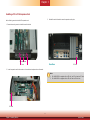
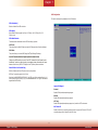
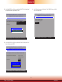
Installing a PCI or PCIe Expansion Card
Use the following procedure to install a PCIe expansion card:
1. Remove the mounting screws to uninstall the card slot bracket.
2. Insert the expansion card in the connector on the
motherboard
and press down until secured.
Rear View
PCIe card
3. Reinstall the card slot bracket to secure the expansion card in place.
Notes:
1. The WM343-KD330 is equipped with one PCIe x16, one PCIe x4 and one PCI slots.
2. The WM343-KD331 is equipped with two PCIe x16 and two PCIe x4 slots.
PCIe card
Screw
Card slot bracket
Page is loading ...
Page is loading ...
Page is loading ...
Page is loading ...
Page is loading ...
Page is loading ...
Page is loading ...
Page is loading ...
Page is loading ...
Page is loading ...
Page is loading ...
Page is loading ...
Page is loading ...
Page is loading ...
Page is loading ...
Page is loading ...
Page is loading ...
Page is loading ...
Page is loading ...
Page is loading ...
Page is loading ...
Page is loading ...
Page is loading ...
Page is loading ...
Page is loading ...
Page is loading ...
Page is loading ...
Page is loading ...
Page is loading ...
Page is loading ...
Page is loading ...
Page is loading ...
Page is loading ...
Page is loading ...
Page is loading ...
Page is loading ...
Page is loading ...
Page is loading ...
Page is loading ...
Page is loading ...
Page is loading ...
Page is loading ...
Page is loading ...
Page is loading ...
Page is loading ...
Page is loading ...
Page is loading ...
Page is loading ...
Page is loading ...
Page is loading ...
Page is loading ...
Page is loading ...
Page is loading ...
Page is loading ...
Page is loading ...
Page is loading ...
Page is loading ...
Page is loading ...
Page is loading ...
Page is loading ...
Page is loading ...
Page is loading ...
Page is loading ...
Page is loading ...
Page is loading ...
Page is loading ...
Page is loading ...
Page is loading ...
-
 1
1
-
 2
2
-
 3
3
-
 4
4
-
 5
5
-
 6
6
-
 7
7
-
 8
8
-
 9
9
-
 10
10
-
 11
11
-
 12
12
-
 13
13
-
 14
14
-
 15
15
-
 16
16
-
 17
17
-
 18
18
-
 19
19
-
 20
20
-
 21
21
-
 22
22
-
 23
23
-
 24
24
-
 25
25
-
 26
26
-
 27
27
-
 28
28
-
 29
29
-
 30
30
-
 31
31
-
 32
32
-
 33
33
-
 34
34
-
 35
35
-
 36
36
-
 37
37
-
 38
38
-
 39
39
-
 40
40
-
 41
41
-
 42
42
-
 43
43
-
 44
44
-
 45
45
-
 46
46
-
 47
47
-
 48
48
-
 49
49
-
 50
50
-
 51
51
-
 52
52
-
 53
53
-
 54
54
-
 55
55
-
 56
56
-
 57
57
-
 58
58
-
 59
59
-
 60
60
-
 61
61
-
 62
62
-
 63
63
-
 64
64
-
 65
65
-
 66
66
-
 67
67
-
 68
68
-
 69
69
-
 70
70
-
 71
71
-
 72
72
-
 73
73
-
 74
74
-
 75
75
-
 76
76
-
 77
77
-
 78
78
-
 79
79
-
 80
80
-
 81
81
-
 82
82
-
 83
83
-
 84
84
-
 85
85
-
 86
86
-
 87
87
-
 88
88


DFI WM343-KD Owner's manual
- Category
- Motherboards
- Type
- Owner's manual
- This manual is also suitable for
Ask a question and I''ll find the answer in the document
Finding information in a document is now easier with AI
Related papers
Other documents
-
Sharkoon 4044951008049 Datasheet
-
Geovision GV-COMV2 Datasheet
-
ATEN IC-422 User manual
-
Wincor Nixdorf Motherboard M1 and M2 POS Operating instructions
-
protech ProX-B501 M2 User manual
-
Aaeon MIX-H310A1 User manual
-
Viglen Vig760S User manual
-
EXSYS EX-47030 Specification
-
Diebold Nixdorf BEETLE /M-III - Mx Operating instructions
-
Aaeon ATX-C246A User manual