Page is loading ...

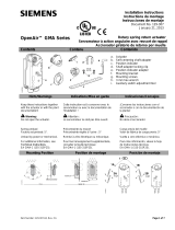
AS100/AS200/AS400
SRA/SRC/ASM
10 11
1 saFetY inForMation
This device complies to current applicable safety standards.
Installation, maintenance and use of this apparatus will have to be done
by skilled and trained staff only.
Please read carefully the whole document prior to mounting and starting-up.
2 asseMBLY
Actuator should be secured directly to the valve using proper bolts or via
a proper interface.
After assembly, the actuator can operate in any position. However, cable
glands should not be oriented upwards (loss of water tightness) and the
motor will preferably not be positioned at the bottom (potential internal
condensation trap)
Note 1 : do not handle the actuator by handwheel, it could damage
the gearworm.
Note 2 : if the actuator was delivered mounted on the valve, the basic
settings should have been done. In this case, refer to § 3,4 and
9 only.
Note 3 : see §.9 for details on storage precaution prior to starting-up.
3 HanDwHeeL operation anD DecLutcHing
In general, the handwheel does not turn during electrical operation.
Even if turning, the solid handwheel does not have any protruding part
and therefore does not present any risk of any kind for the operator.
Moreover, for the actuators with the highest torque, the torque limit
system brings an additional level of protection.
OA models:
These actuators are equipped with a manually declutchable handwheel.
To operate manually the actuator, turn while pulling the handwheel
in order to mechanically engage it.
To declutch the handwheel, just push it back towards the actuator body.
AS100/AS200/AS400/SRA/SRC/ASM models:
These actuators are provided with an automatic declutching handwheel,
with motor drive priority. In order to operate manually the actuator, turn
the arrow of the handwheel clutch button in front of the triangular sign
on the housing (it might be necessary to turn the handwheel by a few
degrees to release the claws). When the motor starts, it returns automa-
tically into declutched position.
WARNING
For explosionproof actuators, please also read carefully the special
instructions TMS1132 prior to mounting and starting-up
ASP/AS50/AS80 models:
Some of these actuators are equipped with declutchable intermediate
gears. By moving the clutch lever, the motor is physically disengaged from
the gears. Once the manual handwheel operation has been completed,
do not forget to clutch the motor back. Otherwise, once started-up,
it would run and heat up until the motor thermal protection switch closes.
If repeated, these conditions can generate a motor breakdown .
4 eLectricaL connections anD preLiMinarY tests
If the actuator is equipped with INTELLI, INTEGRAL, POSIGAM, MINIGRAL or
MINIGAM commands, please report to the specific documentation for wiring
details.
Otherwise, all components of the actuator are wired to a common
terminal strip. Remove the cover and pass the cables through the cable
glands (M20). Refer to the wiring diagram for details on the terminals
numbering system.
Both torque and travel limit switches must be integrated into your
control system (see wiring examples) in order to prevent potential
damage to the actuator or valve.
The following points must be checked:
a) Make sure that power supply voltage is in accordance with the data
engraved on the actuator nameplate,
b) Check that all cable glands are correctly tightened,
c) Move the valve manually to an half-open position,
d) Operate an electrical opening and check that the motor rotates
in the right direction. Press manually on the «OPEN» travel limit
switch ; the motor should stop.
In the same way, check that the closing electrical command as well
as the «CLOSED» travel limit switch are working correctly,
e) All models except OA : operate an electrical opening. Press manually
on the «OPEN» torque limit switch ; the motor should stop.
In the same way, operate an electrical closing check that
the «CLOSED» torque limit switch is working correctly,
If any misfunction was detected at this stage, please check the overall
wiring.
For safer working conditions, we recommend that the power supply now
be switched off especially if the actuator output max. torque exceeds
300 N.m.

12 13
5 setting oF MecHanicaL stops anD traveL
LiMit switcHes
Mechanical stops description and function (1/4 Turn only):
These items avoid any over-travelling during handwheel operations.
The stops can be positioned either on the actuator itself or on the 1/4 Turn
worm gearbox if any.
Actuators and gears are supplied and tested for a 90° operation.
Fine adjustment of the stop screws position is possible within a limit
of ± 2° maximum.
Travel limit switches description and function:
The cams operating the limit switches are on a cylindrical block which
does not require any disassembly. Each cam can be set independently
of the others. The white and black cams are for open and close travel
limits. The other ones are for optional additional limit switches (2 or 4).
How to operate the cams:
a) Put a screwdriver in the slot of the button encircled by the same
color as the cam to be set,
b) Press lightly to disengage the cam of locked position,
c) By turning the screwdriver rotate the cam to the position in which
it can trip the limit switch,
d) Remove screwdriver and ensure that the button has come back to
its original position, thus locking the cam in chosen place.
Procedure of mechanical stops and travel limit switches setting:
a) Loosen stop screws by 2 turns (1/4 Turn only).
b) Manually drive the valve to the closed position. For the 1/4 Turn
devices, if mechanical stops are reached before the valve closing
is completed, it means that the 2° maximum adjustment tolerance
has been exceeded ; do not try to go beyond this limit.
c) Set the cam of the «CLOSED» travel limit switch.
d) T urn stop screws clockwise to the mechanical contact, reloosen
1.5 turn, and secure by lock nut (1/4 Turn only).
Proceed in the same way in open position.
Perform complete electrical valve opening and closing operations.
It is mandatory that the motor stops on the travel limit switch and not
on the mechanical stop (check available extra travel to the stop with
handwheel).
6 setting oF torque LiMit switcHes
IMPORTANT: the torque limit switch design of Bernard Controls actua-
tors gives a short duration contact only. On request, relays holding this
contact maintained can be fitted into the actuator.
Actuators are set and tested in accordance with the torque stated
on orders. If no torque is specified, the actuator is supplied with torque
springs set to the maximum output (refer to our catalogue technical
datasheets).
If necessary, this torque setting can be readjusted by rotating the nuts
which compress the torque springs. So the torque can be increased
or decreased by tightening or loosening the nuts. Please consult us.
7 position FeeDBack potentioMeter (option)
The potentiometer used for actuator signal feedback is driven by the travel
cam block system.
The potentiometer has no mechanical stop and has a non-resistive area
(dead zone) at both the beginning and end of track.
0% position corresponds to a closed valve. 100% to an open valve.
Circuit board mounted version
To mount the potentiometer device on the switch plate, clip it without
the position indicator on the camblock and screw it on the support
column. Screw the position indicator back.
Setting of potentiometer zero is achieved thanks to the «0% postion»
screw.
Drive the actuator to the closed position.
Resistance value is measured between terminals 16 and 17.
Hold the pinion located just under the plate with the «0% position»
marking while driving the potentiometer screw. Adjust the potentiome-
ter so that the resistance value exceeds 0 Ohm and regularly increases
then turn backwards to reach a value as close to 0 Ohm as possible.
Drive the actuator to the open position and write down the resistance
value corresponding to the 100% position.
Come back to the closed position and check that, for the 0% position,
the resistance shows a close to zero repeatable value.
On support column mounted version (OA type of actuactors)
To mount the potentiometer device, screw the support column on the mounting
plate and engage the driving pinion into the camblock wheel.
To adjust the potentiometer resistance value, loosen the nut with the wrench
and rotate potentiometer until the signal requested is archieved.
To set the 0%, drive the actuator to the closed position.
Resistance value is measured between terminals 16 and 17.
Rotate the potentiometer so that the resistance value exceeds 0 Ohm
and regularly increases then turn backwards to reach a value as close
to 0 Ohm as possible.
Retighten nut after setting.

14 15
Drive the actuator to the open position and write down the resistance
value corresponding to the 100% position.
Come back to the closed position and check that, for the 0% position,
the resistance shows a close to zero repeatable value.
Note: If actuator is equipped with 2 potentiometers, each potentiometer
is set independently of the other.
Signal inversion:
To inverse the signal variation direction, invert potentiometer wires
on the actuator terminal board (e.g. for a connection on 16/17/18, invert
16 and 18).
8 «taM» position transMitter (option)
The TAM transmitter delivers a 0/4 to 20 mA signal linearly proportional
to the angular position of the valve.
Electric connections
Refer to the wiring diagram supplied with the actuator. See also some
typical wiring examples below.
Filtered or stabilised power supply should be provided within the 12 to
32 VDC range.
Maximum admissible ohmic load values are given in the table :
Signal direction inversion
The TAM transmitter, when supplied with a standard actuator, provides
a signal that rise from close position to open position, the standard
opening direction being counter-clockwise.
If an opposite signal variation is required, simply move 2 jumpers on the board
near the potentiometer.
Direct signal : jumpers on 1-3 and 2-4
Reversed signal : jumpers on 1-2 and 3-4
Energy Supply
DC (VOLT)
Max. admissible
load Ohm
12 150
24 750
30 1050
Settings
Connect a milliampermeter at the place of burden.
- Always start by adjusting the 0/4mA.
- Drive actuator to the position corresponding to the 0/4 mA (closed
in standard),
- Hold the pinion located just under the plate with the «0% position»
marking while driving the potentiometer screw. Adjust the poten-
tiometer so that the output current reaches a minimum value. Turn
backwards until the current value regularly increases then turn
backwards again and stop as soon as the minimum value determined
here above has been reached.
The potentiometer is then positioned at the very beginning of its track.
- Then, use the TAM adjustment screw marked as «0/4mA» to adjust
the current to a value as close to the 0/4 mA as possible.
- Drive actuator to the position corresponding to the 20 mA (open
in standard),
- Turn the screw marked «20mA» in order to read exactly 20 mA
on the milliampermeter.
- Come back to the closed position and check that, for the 0% position,
the signal current shows a close to 0/4 mA and repeatable value.
9 Maintenance anD storage instructions
Maintenance
If actuator is correctly mounted and sealed, no special maintenance
is required. Check once a year function of motor and make sure that
switch compartment is condensation free. If environment is humid, we
recommend installation of an anti-condensation heater resistance and/
or breathers, thus protecting electric parts from alteration.
Actuators are lubricated with grease for about 100.000 operations. If the
grease requires to be renewed, use one of the products listed hereafter.
NOTE : When renewing the grease, first remove the integrality of the
old one.
General characteristics of lubricant ; grease specifications only (not ac-
tuator) given for standard duty conditions :
• Grease duty temperature : -30°C to +135°C,
• Penetration ASTM at +25°C : 265/295,
• Drop point : +180°C.
eQuivalent grease table
(normal conditions)
TOTAL
MULTIS COMPLEX EP2
SHELL
ALVANIA EP2
MOBIL
MOBILUX EP2
ESSO
BEACON EP2

16 17
Storage
The actuator includes electric equipment as well as grease lubricated
gear stages. In spite of the weatherproof enclosure, oxydising, jamming
and other alterations are possible if actuator is not correctly stored.
Actuators stored in a stock room
a) The actuators should be stored under a shelter, in a clean and
dry place and protected from wide temperature variations. Avoid
placing the actuators directly on the floor.
b) For actuators equipped with an heating resistance, it is recom-
mended to connect and power supply it especially if the storage
area is humid (standard 230 VAC, unless other specification).
c) Check that the temporary sealing plugs of the cable entries are well
in place. Make sure that the covers and the boxes are well closed
to ensure weatherproof sealing.
d) In the case of a valve with rising stem having a long stroke, verify
that the protection tube is well mounted on the actuator. If not,
fix it with sealing paste.
Actuators installed but waiting for electrical connection
If a long period of time is expected between the actuator mounting
and the electrical wiring works :
a) Visually check the tightness of electrical box cover and cable glands.
b) Cover the device with a plastic protective film.
c) For actuators equipped with an heating resistance, it is recom-
mended to connect and power supply it especially if the storage
area is humid (standard 230 VAC, unless other specification).
Storage of actuators equipped with electronic components:
Long term storage of electronic components which are not in service increases
the malfunction risk. This practice is therefore highly unadvisable.
If a long term storage is absolutely necessary, we strongly recommend
a revision of the electronic boards in our factory before actuator usage.
Control after storage:
a) Visually check the electric equipment,
b) Operate manually the microswitches, buttons, selectors, etc., to insure
the correct mechanical function,
c) Operate apparatus manually,
d) Verify the correct grease consistency,
e) For actuators equipped with grease nipple, remember to complete
with some fresh grease.
1 sicHerHeitsinForMationen
Das Gerät erfüllt die geltenden Sicherheitsstandards.
Die Installation, Wartung und Verwendung dieses Geräts darf nur durch
qualifiziertes und geschultes Personal erfolgen.
Lesen Sie sich vor der Montage und Inbetriebnahme das gesamte Doku-
ment sorgfältig durch.
2 Montage
Der Servomotor muss mithilfe von geeigneten Schrauben oder einem
geeigneten Zwischenstück direkt am Ventil befestigt werden.
Nach der Montage kann der Servomotor beliebig ausgerichtet wer-
den. Die Kabelverschraubungen dürfen jedoch nicht nach oben weisen
(Verlust der Wasserdichtigkeit), und der Motor sollte nicht am tiefsten Punkt
platziert werden (mögliche Ansammlung von internem Kondenswasser).
Anmerkung 1: Betätigen Sie den Servomotor nicht per Handrad, da dies
den Antrieb beschädigen könnte.
Anmerkung 2: Wenn der Servomotor bereits auf dem Ventil montiert
geliefert wurde, sind die Grundeinstellungen bereits
erfolgt. Beachten Sie in diesem Fall ausschließlich die
Absätze 3, 4 und 9.
Anmerkung 3: Details zu Vorsichtsmaßnahmen bei der Lagerung vor
der Inbetriebnahme finden Sie in Absatz 9.
3 HanDraDBetätigung unD auskuppeLn
In der Regel kommt es im elektrischen Betrieb zu keiner Drehung des
Handrades. Auch wenn es sich dreht, besitzt das massive Handrad
keine vorstehenden Teile, sodass davon keine Gefahr für den Bediener
ausgeht. Für die Servomotoren mit dem höchsten Drehmoment bietet
das Drehmoment-Begrenzungssystem zusätzliche Sicherheit.
OA-Modelle:
Diese Servomotoren sind mit einem manuell auskuppelbaren Handrad
ausgestattet.
Um den Servomotor manuell zu bedienen, drehen Sie das Handrad unter
leichtem Ziehen, somit wird es mechanisch eingerastet.
Um das Handrad auszukuppeln, drücken Sie es in Richtung des Servo-
motorgehäuses zurück.
WARNUNG
Lesen Sie bei Servomotoren für den Einsatz in
explosionsgefährdeten Bereichen vor der Montage und Inbetriebnahme
die besonderen Hinweise TMS1132 sorgfältig durch.

26 27
EXEMPLES DE CIRCUITS PUISSANCE - EXAMPLES OF POWER SUPPLY WIRING
BEISPIELE FÜR STROMVERSORGUNGSKREISE
(*) pour les modèles OA pré-câblés, voir exemples de réalisation
de coffret de commande page suivante
(*) for pre-wired OA models, see examples of control panel design
on next page
(*) für vorverdrahte einphasige OA-Modelle siehe Beispiel für
Steuerungsausführung auf der nächsten Seite
version non pré-câblée (*) / not pre-wired version / nicht gültig für vorverdrahte Versionen (*)
Légende : C1 = contacteur ouverture ; C2 = contacteur fermeture
Legend : C1 = opening contact; C2 = closing contact
Legende : C1 = Öffnungsschaltschütz; C2 = Schließungsschaltschütz
3 PHASES / DREI PHASEN 1 PHASE / EINE PHASE
EEX E D
Connection / Anschluß
Ouvert
Open
AUF
Fermé
Closed
ZU
E1 : Sectionneur + fusible
E2 : Relais thermique
C1 : Contacteur OUVERTURE
C2 : Contacteur FERMETURE
C3 : Contacteur DEFAUT
FCO : Fin de course OUVERTURE
FCF : Fin de course FERMETURE
LEO : Limiteur d'eort OUVERTURE
LEF : Limiteur d'eort FERMETURE
LT : Protection thermique moteur
TR : Transformateur
B1 : Bouton poussoir OUVERTURE
B2 : Bouton poussoir FERMETURE
E1 : Circuit breaker+ fuse
E2 : Thermal relay
C1 : OPENING Contactor
C2 : CLOSING Contactor
C3 : DEFAULT Contactor
FCO : OPEN travel limit switch
FCF : CLOSE travel limit switch
LEO : OPEN torque limit switch
LEF : CLOSE torque limit switch
LT : motor thermal protection
TR : Transformer
B1 : Opening push button
B2 : Closing push button
Defaut
Störung
Acquittement défaut limiteur d'eort
Torque limit default acknoledgement
Fehlerquittierung
Arrêt sur limiteur d'eort
à la fermeture : nous consulter.
Stop on torque limit switch
in the closing direction : please consult us.
Beispiele für das drehmomentabhängige
Abschalten in Schließrichtung auf Anfrage.
Exemple 1 - Arrêt en position ouverture et fermeture sur contact n de course avec limiteur d'eort en sécurité
avec réarmement. Schéma valable pour toute la gamme SD sauf OA monophasés pré-câblés (voir exemple 2).
Pour les servomoteurs modèle OA, non équipés de limiteurs d'eort : partie A du schéma seulement.
Example 1 - Stop on travel limit switch on closing and opening directions, torque limit switch in safety action with
manual reset. Diagram valid for the entire SD range excepted the pre-wired one phase OA model (cf. example 2).
For OA actuators, not equipped with torque limit switch : side A of the diagram only.
Beispiel 1 - Abschaltung in OFFENER und GESCHLOSSENER Position über Wegschalter. Die Drehmomentschalter
schalten bei Überlast ab. Schaltplan für die ganze SD Baureihe außer vorverkabelte einphasige OA Modelle verfügbar
(siehe Beispiel 2).
Für die OA Modelle, die mit Drehmomentschalter nicht ausgestattet sind : nur Teil A von dem Schaltplan
Servomoteur
Actuator / Antrieb
EXEMPLES DE REALISATIONS DE COFFRETS DE COMMANDE
CONTROL PANEL SAMPLE DESIGN / BEISPIEL FÜR STEUERUNGSAUSFÜHRUNG
Les servomoteurs sont représentés en position médiane / Actuators are represented in an intermediate position
Die Antriebe sind in Mittelposition dargestellt
Arrêt
Stop
Stopp
E1 : Hauptschalter / Sicherung
E2 : Motorschutzschalter
C1 : Motorschütz ÖFFNEN
C2 : Motorschütz SCHLIESSEN
C3 : Motorschütz FEHLER
FCO : Wegendschalter AUF
FCF : Wegendschalter ZU
LEO : Drehmomentschalter ÖFFNEN
LEF : Drehmomentschalter SCHLIESSEN
LT : Temperaturwächter Motor
TR : Transformator
B1 : ÖFFNEN
B2 : SCHLIESSEN
VECTORISE
NON VECTORISE
fermé / closed / ZU
ouvert / open / AUF
CABLAGE CLIENT / CUSTOMER WIRING
KUNDE VERDRAHTUNG
OUVERT / OPEN / AUF
FERME / CLOSED / ZU
Alimentation monophasée
Single phase power supply
Einphasige Stromversorgung
10
11
Condensateur / Capacitor
Kondensator
CABLAGE SERVOMOTEUR / ACTUATOR WIRING / ANTRIEB VERDRAHTUNG
1
2
4
3
5
OUVERT / OPEN / AUF
6
Résistance de chauage
Heating resistance
Heizwiderstand
Contacts n de course /
Travel limit switches
Wegendschalter Kontakt
FERME / CLOSED / ZU
Protection thermique moteur
12
Motor thermal protection
Temperaturwächter Motor
Exemple / Example / Bespiel 2 :
Servomoteurs OA monophasés
pré-câblés - Arrêt en position
ouverture et fermeture sur n
de course.
Pre-wired one phase OA actuators
Stop on travel limit switch on both
opening and closing directions.
Vorverdrahte einphasige OA-Modelle
Abschaltung in OFFENER und
GESCHLOSSENER Position über
Wegendschalter.
VECTORISE
NON VECTORISE

BERNARD CONTROLS
4 rue d’Arsonval - BP 70091 - 95505 Gonesse Cedex - France
Tel: +33.1. 34.07.71.00 - Fax: +33.1.34.07.71.01
E-mail: mail@bernardcontrols.com
Internet: http://www.bernardcontrols.com
SUBSIDIARIES
BELGIUM
BERNARD CONTROLS
BENELUX
BRUXELLES
info.benelux@bernardcontrols.com
Tel +32 (0)2 343 41 22
CHINA
BERNARD CONTROLS CHINA
PEKIN
bcc.info@bernardcontrols.com
Tel +86 (0) 10 6789 2861
GERMANY
BERNARD CONTROLS DEUFRA
TROISDORF
bcd.mail@bernardcontrols.com
Tel +49 22 41 98 340
ITALIA
BERNARD CONTROLS ITALIA
MILAN
info.it@bernardcontrols.com
Tel +39 02 931 85 233
KOREA (REPUBLIC OF)
BERNARD CONTROLS KOREA
SEOUL
bck.info@bernardcontrols.com
Tel +82 02-2270-3880
SINGAPORE
BERNARD CONTROLS SINGA-
PORE
SINGAPORE
bcsg.info@bernardcontrols.com
Tel +65 65654227
BERNARD CONTROLS SPAIN
MADRID
info.spain@bernardcontrols.com
Tel +34 91 30 41 139
UNITED STATES
BERNARD CONTROLS Inc
HOUSTON
bsales@bernardcontrols.com
Tel +1 281 578 66 66
OFFICES
BANGKOK
BERNARD CONTROLS
SOUTH-EAST ASIA
j.chounramany@bernardcontrols.com
Tel +66 2 640 82 64
DUBAÏ
BERNARD CONTROLS
MIDDLE-EAST
bernact@emirates.net.ae
Tel +971 4 344 2010
MOSCOW
BERNARD CONTROLS
RUSSIA
youri.otradine@bernardcontrols.com
Tel +(7 499) 251 06 54
or +(7 916) 911 28 42
AGENTS AND
DISTRIBUTORS
AMERICAS
Information on our network
www. bernardcontrols.com
or
Back Office
BERNARD CONTROLS Inc.
bsales@bernardcontrols.com
Tel +1 281 578 66 66
BRAZIL
JCN
SAO PAULO
Tel +55 11 39 02 26 00
ASIA
Information on our network
www. bernardcontrols.com
or
To contact our distributors
Back Office
BERNARD CONTROLS ASIA
bcc.info@bernardcontrols.com
Tel +86 10 6789 2861
EUROPE - MIDDLE
EAST - AFRICA
Information on our network
www.bernardcontrols.com
or
Back Office
BERNARD CONTROLS
mail@bernardcontrols.com
Tel +33 (0)1 34 07 71 00
or
Contact directly agents/distributors
AUSTRIA
IPU ING PAUL UNGER
WIEN
Tel +43 1 602 41 49
CZECH REPUBLIC
FLUIDTECHNIK BOHEMIA s.r.o.
BRNO
brno@fluidbohemia.cz
Tel +420 548 213 233-5
DENMARK
ARMATEC A/S
COPENHAGUEN
Tel + 45 46 96 00 00
EGYPT
ATEB
ALEXANDRIA
gm@atebco.com
Tel +203 582 76 47
FINLAND
TALLBERG TECH OY AB
ESPOO
info@tallberg.fr
Tel +358 0 207 420 740
GREECE
PI&MS Entreprises Ltd
ATHENS
Tel +30 210 608 61 52
HUNGARY
APAGYI TRADEIMPEX KFT
BUDAPEST
Tel +36 1 223 1958
MOROCCO
AQUATEL sarl
CASABLANCA
Tel +212 22 66 55 71
POLAND
ARNAP
BIELSKO-BALA
Tel +48 33 81 84004
MARCO
VARSOVIE
Tel +48 22 864 55 43
SOUTH AFRICA
A-Q-RATE AUTOMATION CC
BERTSHAM
Tel +27 11 432 58 31
SWITZERLAND
MATOKEM AG
ALLSCHWIL
info@matokem.ag
Tel +41 61 483 15 40
TURKEY
OTKONSAS
ISTANBUL
Tel +90 216 326 39 39
UNITED KINGDOM
ZOEDALE Plc
BEDFORD
Tel +44 12 34 83 28 28
Exhaustive list of agents
and distributors on
www.bernardcontrols.com
/