Page is loading ...

Installation manual
MAXI MVD VR4+
English
MS BRANCH BOX
CL23284 to CL23286
CL23280
to CL23282
MVD
www.mundoclima.com

●
Please entrust the distributor or professionals for
installation.Installation personnel must own related professional
knowledge. If installed by oneself, improper installation may lead
to fire, electric shock, injury and water leakage etc.
● Local purchased components must use the products assigned
by our company
. Use the unassigned products may lead to fire,
electric shock, injury and water leakage etc., please entrust the
professionals to install Retail parts.
●
When installing the unit in a small room, take measures against
to keep refrigerant concentration from exceeding allowable
safety limits in the event of refrigerant leakage.
● Contact the distributor for specific measures.
●
For electrical work, follow the local national wiring standard,
regulation.According to the law
, that must install with the
dependable grounding engineering. If electrical grounding is not
enough or defect in electrical work, it will cause electrical shock.
●
Please entrust the distributor or professionals for installation
when the air-conditioner is needed to move or re-installation.
Improper installation may lead to fire, electric shock, injury and
water leakage etc.
● Never do the remodeling or repair by yourself.
●
Improper repairing may lead to fire, electric shock, injury and
water leakage etc.,please entrust the distributor or professionals
for repairing.
●
If the supply cord is damaged, it must be replaced by the
manufacturer, its service agent or similarly qualified persons in
order to avoid a hazard.
● This appliance can be used by children aged from 8 years and
above and persons with reduced physical, sensory or mental
capabilities or lack of experience and knowledge if they have
been given supervision or instruction concerning use of the
appliance in a safe way and understand the hazards involved.
Children shall not play with the appliance. Cleaning and user
maintenance shall not be made by children without supervision.
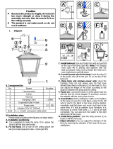
CAUTION
●
Do not install the MS near the strong electromagnetic
interference environment, otherwise will cause the MS
communication error.
● For the MS may produce refrigerant noise, please do not install
it at the silent places, such as sleeping room, hospital sickroom,
dedicated silent room etc., recommendinstalling it at the corridor
or washing room etc.
●
Be sure to install drain piping in order to ensure proper
drainage.
●
Improper drain piping may result in water leakage and bedewing
furniture etc.
●
Be sure to install an earth leakage breaker. Failure to install an
earth leakage breaker may result in electric shocks.
●
Do not install the MS at any place where flammable gas may
leak out.
● If the gas leaks out and stays around the MS, a fire may break
out.
● Read "PRECAUTIONS" carefully before installation.
●
The following precautions include important safety items. Observe
them and never forget.
●
Keep this manual with the owner's manual in a handy place for
future reference.
●
The A-weighted sound pressure level is below 70 dB.
1. PRECAUTIONS
WARNING
WARNING
The safety precautions listed here are divided into two categories. In
either case, important safety information is listed which must be
read carefully.
After completing the installation, make sure that the unit operates
properly during the start-up operation. Please instruct the customer
on how to operate the unit and keep it maintained.Also, inform
customers that they should store this installation manual along with
the owner's manual for future reference.
Failure to observe a warning may result in death.
CAUTION
Failure to observe a caution may result in injury or
damage to the equipment.
CONTENTS PAGE
1. PRECAUTIONS...................................................................................1
2. INSTALLA
TION INFORMATION...........................................................2
3. ACCESSORIES AND LOCAL PURCHASED COMPONENTS
...................
3
4. INSTALLATION...................................................................................4
5. ARRANGEMENTS FOR DRAINAGE PIPE.............................................5
6. INST
ALL THE CONNECTING PIPE.......................................................6
7. WIRING..............................................................................................9
8. APPLICATION CONTROL...................................................................11
9. TEST OPERATION..............................................................................12
Installation manual Maxi MVD VR4+
●
Be sure to be in conformity with the local, national and
in
ternational laws and regulations.
●
The model names in the manual are using acronyms, for
example, MS02 is short for MVD
-MS02/N1-C.
2

2. INSTALLATION INFORMA
TION
●
Be sure to install at a strong and firm foundation or ceiling base.
If the foundation or ceiling base is not strong and firm enough,
the set will drop to cause injury.
● Connect the electric cable correctly.
If wrong connecting the electric cable, then it will damage the
electrical components.
●
Expose the unit to the water or other moisture before installation
will lead to the short circuit of the electrical components.
●
Don’t store the unit in the humid basement or expose to the rain
or water.
If refrigerant leaks happen during installation, then ventilate
the room immediately.
If refrigerant leak and is exposed to the fire, then will produce
toxic gas.
●
After finishing the installation work, be sure to check whether
the refrigerant leak or not.
CAUTION
●
Location in the following places may cause malfunction of the
machine. (If can’t avoid that, please consult the professionals):
●
This series air-conditioner is comfort type air-conditioner, do not
use for the machine room, precise machine, food, plants,
animals, art-work etc. rooms.
2.1 MS installation location
2.2 MS Installation and maintenance
needed space
1. A place can provide enough installation and maintenance
space.
2. Horizontal ceiling and its building construction is able to
withstand the set’
s weight.
3. A place where the connecting pipes and drain pipes can
outlet easily.
4. The installation location should consider the length of the
refrigerant pipe connected with the outdoor and indoor
units,can not exceed the limited length range.
1.5m or less 1.5m or less
Pipe
hanger
Refrigerant
pipe
Ceiling concrete
Do not install the MS to close to the ceiling Tex(minimum 50mm)
Ceiling tex
0.3m or more
400mm
or more
500mm
or more
400mm or more
700mm or more
Fig.2-1
Fig.2-2
Installation manual Maxi MVD VR4+
1. A place where is full of mineral oil like cutting oil etc.
2.
A place where salty air surrounding such as near the coast
etc.
3. A place where is full of caustic gas such as the sulfide in hot
spring.
4. A place with serious mains voltage fluctuation.
5. A place inside the automobile or cabin etc.
6. A place with oil gas, such as kitchen.
7. A place where high-frequency electromagnetic waves are
generated.
8. A place with flammable gas or material.
9. A place with acidic or alkaline gas.
10.Other special conditions places.
3

3. ACCESSORIES AND LOCAL PURCHASED COMPONENTS
Please check whether the following fittings are of full scope. If there are some spare fittings , please restore them carefully.
Table: 3-1
Table: 3-2
《ACCESSORIES》
No
te
Φ6.4×0.8
Φ12.7×0.8 Φ15.9×1.0
Φ9.5×0.8
Copper Pipes
(Drawn copper pipes
GB1527-1987)
Indoor unit capacity
Liquid side pipe
Gas side pipe
2.2~4.5kW 5.6~16.0kW
Use for the connection
of MS and indoor
unit refrigerant system,
recommend using soft
copper pipe (TP2M).
The length selection is
according to actual
needs.
PVC drainage pipe
Heat-insulated pipe
For drainage pipe of MS, according to the actual needs for the length.
The inner diameter should be same with the relative copper pipes and PVC pipes, the
thicknessshould be (more than) 10mm, especially thicker for the closed wet area.
《LOCAL PURCHASED COMPONENTS》
Installation manual Maxi MVD VR4+
4
QTY.
SHAPE
USE
1
1
1
For the MS installation
and operation instructions
For heat insulation
of pipe connectors
2-12
(Follow the MS model)
1-11
(Follow the MS model)
Connect the drainage
port of MS and the
PVC water pipe.
Fasten the connector
between flexible drainage
pipe and MS drainage
port.
1 pair
(for MS02E)
1 pair
(for MS04E)
Parallel connect the two
groups of pipes, to
enlarge the capacity
output
1 pair (for MS01)
2 pairs(for MS02)
4 pairs(for MS04)
6 pairs(for MS06)
Use for the indoor unit
capacity is 2.2~4.5kW
NAME
Installation &
operation manual
Heat-insulated pipe
Flexible drainage pipe
Snapring
Three-way connector
Adapter pipe
Copper nut
Five-way connector
Use for connecting the
pipes of the indoor unit
1
(for MS01)
Adapter pipe
Use for connecting
the liquid side of the
outdoor unit

4. MS INSTALLATION
WARNING
Fig.4-1
● Install at an enough strength location which is able to withstand
the set’s weight.
●
If the strength is not enough or installation is not properly done,
the set will drop to cause injury.
●
Carry out special installation work to prevent strong wind or
earthquake.
● If install by halves, the set will drop to cause accident.
4.1 Install the main body
4.2 The installation of hanging screw bolts
4.1.1 Install the Φ10 hoisting screw
4.1.2 Hoisting install the MS
1. Please use Φ10 hoisting screw
.
2. Remove the ceiling: For different architectural structure, details
please contact with indoor decoration personnel.
a. Ceiling: For make sure the ceiling level and for avoiding to the
ceiling vibration, it must be strengthened the ceilingplate base
frame.
b. Do not cut off the ceiling plate base frame.
c. Strengthen the base frame on the both sides of the fixed
ceiling.
d.
After hoisting install the main body, it should do the piping and
wiring work in the ceiling, decide the outlet directionsof the pipes
after selected the installation location. Especially for the position
already has ceiling, please installpipe, drainage pipe, indoor and
outdoor units connecting wires and wire controlling wire to the
connecting positionsbefore hoisting the unit.
1. Please use the pulley to hoisting install the indoor unit on the
hoisting bolt.
2. Please use the gradienter to adjust the indoor unit to be
horizontal, if not, it may cause water leakage.
The installation situations of hanging screw bolts refer to the
following (Table 4-1 and 4-2)
W
ooden structure W
ooden structure
Put rectangular sticks across the beams, and set pendant bolts.
Wooden span
Beam
Ceiling
Pendant bolt
Set and use supportive angle steel.
Steel beam and girder structure
Suspended bolt
Pendant bolt
Supportive angle steel
Wooden structure Wooden structure
Set it with embedded bushes or embedded bolts.
New concrete roughcast
Flap type inser
Slide type inser
Concrete iron
Embedded bolt
(With embedded
bolt in pipe)
Old concrete roughcast Old concrete roughcast
Use embedded bolts and embedded pulling plugs.
Table: 4-1
Table: 4-2
CAUTION
The bolt material is the high quality carbon steel (galvanized or
covered other rust preventive materials on the surface) or
rustless steel.
The ceiling rust prevention measure is conducted according to
actual construction, for detail method please consult building
engineer.
Suspending bolts must be fixed, the fixing method as per to the
actual situation.
4.3 Dimension Figure
A
D
B
E
C
J
K
I
H
G
F
Table: 4-3
Installation manual Maxi MVD VR4+
5
Model
MS02 & MS02E
MS04 & MS04E
MS06
A
630
960
960
600
600
600
490
820
820
310
310
310
225
225
225
B C D E
Model
MS02 & MS02E
MS04 & MS04E
MS06
F
Φ25.4
Φ32
Φ32
Φ19.1
Φ22
Φ22
Φ12.7
Φ16
Φ16
Φ24.5
Φ24.5
Φ24.5
G H I
Model
MS02 & MS02E
MS04 & MS04E
MS06
J
7/8"14UNF-2A
7/8"14UNF-2A
7/8"14UNF-2A
5/8"18UNF-3A
5/8"18UNF-3A
5/8"18UNF-3A
K
MS01
MS01
MS01
7/8"14UNF-2A 5/8"18UNF-3A
630 600 490 310225
Φ19.1 Φ16 Φ9.52 Φ24.5

4.4 Hanging the MS
1. Adjust the nut’s site, the interval between gasket (Down Side) and
the ceiling should according to actual construction. See Fig.4-2
2. Hang the nut of hanging screw bolt into the slotted hole of the
installing ear.
3. Use the level gauge to confirm the horizontality of the unit.
(Prohibitfalling toward non-drainage side, better to fall a little
toward the drainage side) See Fig. 4-3.
5 ARRANGEMENTS FOR DRAINAGE PIPE
5.1 MS drain pipes installation
1. Please use the flexible drainage pipe to connect the MS drainage
port and the PVC pipes, and use the snap ring for fastening.
2. While connecting other drain pipes please use hard PVC binder
and check whether leak or not.
3. The waterspout joints and drain pipes (especially the indoor parts)
of the main unit have to wrap up evenly by insulated casing pipes,
and tighten up with lacing belt, in order to prevent air admission
and cause condensation.
4. For avoiding to the condensate water reflow to the air-conditioner
inner, the drain pipes should incline toward the outdoor side
(drainage side), the gradient should be over 1/100, and do not turn
up defect as prominence and water absorb etc.(See Fig.5-2a)
5. While connecting the drain pipes, do not pull so hard for avoiding
the main unit effect by force.
The transverse pull-out of the drain
pipes should be within 20m, meanwhile, set a supporting point
every 0.8~1.0m, for avoiding the flexure of drain pipes ( See
Fig.5-1b); use hard polyethylene (PE)PE pipes to connect the
drain pipes and the connecting pipes, and use the connecting
pipes to fasten the drain pipes (See Fig.5-2b) .
6. Central install the drain pipes please follow Fig.5-2 to match pipes.
7. The end of the drain pipe should leave the ground or the bottom of
the drain tank more than 50mm, and should not put into the water.
While directly pour the condensate water into foul sewer, must
make the sparge pipe bend up to a U-shape water seal, in order to
avoid the fetor come into the indoor through the drain pipe.
Fig.4-2
Fig.5-1
Fig.4-3
CAUTION
For avoiding water leakage, every joint of the drainage system
must be sealed up.
0.8~1.0 m
a
>1.0 m
b
Fig.5-2
Gradient:
higher than 1/100
b
Fig.5-3
5.2 Drainage test
5.2.1 Before doing drainage test should keep the drainage
piping smooth, and check every joint whether sealed up or
not.
5.2.2 For newly built room, do the drainage test before paving
the ceiling.
1. Use a water main to fill the water tank with 500~1000ml water.
2. Check whether drained water normally and whether has
leakage on the connectors.
Snap
ring
Water container
Flexible drainage
pipe
Outlet
PVC water
pipe(Φ25)
Hard PVC binder
Hanging Bolt
Installing lug
Gasket(Up Side)
Nut(Up Side)
Nut(Down Side)
Gasket(Down Side)
Down Side of the ceiling
Level gauge
Be sure to fasten it!
Downside gradient
over 1/100
As long as possible(about 10cm)
VP30
Installation manual Maxi MVD VR4+
6

6 INSTALL THE CONNECTING PIPE
6.1 Range of MS application
6.2 Connecting diagram of MS and indoor unit
Connecting diagram 1
indoor unit
indoor unit
indoor unit
indoor unit
indoor unit
indoor unit
max:4 units, max capacity:16kW
max:4 units, max capacity:16kW
max:4 units, max capacity:16kW
max:4 units, max capacity:16kW
max:4 units, max capacity:16kW
max:4 units, max capacity:16kW
Suitable model
MS02E
Note
Match with large capacity duct type unit(20.0kW~28.0kW)
Connecting diagram 2
indoor unit
max: 1 unit, max capacity: 28kW
indoor unit
max: 1 unit, max capacity:56kW
Suitable model
MS04E
Note
Match with large capacity duct type unit(40.0kW~56.0kW)
Connecting diagram 3
6.3 Requests for the length of pipes connected
indoor and outdoor units with the MS and
altitude difference
1. Allowable pipe length please refers to the outdoor unit instruction.
2.
Allowable pipe altitude difference please refers to the outdoor unit
instruction.
CAUTION
● Do not let air, dust, or other impurities fall in the pipe system
during the time of installation.
●
The connecting pipe should not be installed until the indoor
and outdoor units have been fixed already.
●
Keep the connecting pipe dry, and do not let moisture in
during installation.
● The connecting copper pipes should be wrapped up by
insulated materials (more than 10mm thick).
}
total max capacity:
28kW(for MS02)
45kW(for MS04/06)
Table: 6-1
Table: 6-2
Installation manual Maxi MVD VR4+
Suitable model
MS02
MS04
MS06
Note
1.Capacity matching with each indoor unit group is lower than16kW.
2.If the indoor units do not have auto mode function, then each group
of MS can be connected with four indoor units at most for one time; other
wise, it can be connected with only one indoor unit at most.
3.Indoor units in the same group of MS can not be operated in cooling or
heating mode at the same time, or operated in heating and air supplying
mode at the same time,otherwise it will be mode conflict.
7
MS outside drawing Model
M
a
x. connecting
indoor unit
quantity
Max. total
indoor unit
capacity
MS02 4×2=8
28kW
MS04 4×4=16 45kW
MS06 4×6=24 45kW
M
S
02E 1 28kW
MS04E 1 56kW
MS
01 4×1=4
16kW

6.4 Pipe size
(Unit: mm)
6.4.1 MS pipe size
6.4.2 S Indoor unit pipe size
Φ12.7
Φ15.9
Φ6.4
Φ9.5
Lower side indoor
unit capacity A
(×100W)
Branch pipe side (mm)
Gas pipe Liquid side
Suitable
branch pipe
22≤
A≤45
45<A≤160
FQZHN-01D
FQZHN-01D
6.5 The Procedure of Connecting Pipes
1. Measure the required length of the connective pipe, and make the
connective pipes in the following procedure. (Refer to Pipeline
Connection for details)
1) Connect the indoor unit first, and then connect the outdoor unit.
a. The pipe bend should be handled carefully
, without damaging the
pipe and insulation layer.
b. Before screwing up the flared nut, apply refrigerant oil at the outer
surface of the pipeline flare and the taper surface of the connec-
tion nut. Screw up the nut for 3~4 circles beforehand (see
Fig.6-1).
Fig.6-1
Apply refrigerant oil
c. When connecting or disconnecting the pipeline, be sure to use two
spanners concurrently.
d. Do not rest the weight of the connective pipe on the adapter of the
indoor unit.
Too heavy load on the adapter of the indoor unit may
deform the pipe and thus affect the cooling/heating effect.
2) The valve of the outdoor unit should be closed completely (as in
the factory status). Every time when connecting the pipe, screw of
f
the nut at the valve, and connect the flared pipe (within 5
minutes). If the nut is put away for a long time after being screwed
off the valve, dust and other foreign substance may intrude into
the pipeline system and lead to fault.
3) After the refrigerant pipe is connected to the indoor and outdoor
units, expel air as instructed in the “Expel air” section. After
expelling the air, screw up the nut at the maintenance orifice.
a. Precautions for the flexible part of the pipeline
i.The bend angle shall not exceed 90°. (See Fig.6-2)
ii. The bend shall be preferably in the middle of the pipe length,
and higher bend radiuses are preferred.
iii. Do not bend the flexible pipe for over 3 times.
b. Bend the thin-wall connective pipe (See Fig.6-3)
i. When bending the pipe, cut out a notch of the desired size at the
bend of the adiabatic pipe, and then expose the pipe (wrap the
pipe with the wrapping tape after bending it).
ii. The radio of the elbow pipe should be as large as possible to
prevent flattening or crush.
iii. Use the pipe bender to make close elbow pipe.
c. Use purchased copper pipe
When the cooper pipe is purchased from the market, be sure to
use the heat insulation materials of the same type (with a
thickness of over 9mm).
2. Deploy the pipelines
1) Drill a porthole on the wall, and put the hole sheath and hole
cover through the wall.
2) Place the connective pipe together with the indoor & outdoor
connection wires. Use wrapping tape to tie them tight. Do not let
air penetrate into it lest condensation and drips of moist.
3) Pull the connective wrapped connective pipe from outdoor
through the sheath, which gets through the wall, and lead it into
the room.
3. Make a vacuum of connective pipeline.
4. After the above steps are completed, the spool of the valve of
the outdoor unit should be completely open, and the refrigerant
pipeline of the indoor unit and the outdoor unit should be
smooth.
5. Use a leak detector or soap water detect leak carefully to
prevent leakage.
6. Put on an adiabatic envelope (accessory) at connective pipe
adapter of the indoor unit, and wrap it tight with the wrapping
tape lest condensate and leakage.
Fig.6-2
Fig.6-3
Use a thumb to bend the pipe
Minimum radius 100mm
Method of unleashing the spooled pipe
Straighten the pipe end
Table: 6-3
Table: 6-4
Installation manual Maxi MVD VR4+
8
Model
Note
MS2 &
MS02E
Liquid pipe
Liquid pipe
MS04 &
MS04E
MS06
Connect
the outdoor
unit side
Connect
the indoor
unit side
High
pressure
gas pipe
Low
pressure
gas pipe
Low
pressure
gas pipe
Use for the connection of the indoorunit refrigerant
system, recommend using soft copper pipe (TP2M).
The length selection is according to actual needs.
Φ12.7
Φ19.1
Φ25.4
Φ9.5
Φ15.9
Φ15.9
Φ22.2
Φ31.8
Φ9.5
Φ15.9
Φ15.9
Φ22.2
Φ31.8
Φ9.5
Φ15.9
MS01
Φ9.5
Φ15.9
Φ9.5
Φ15.9
Φ19.1

1. Flare
1) Use a pipe cutter to cut off the pipe (See Fig.6-4)
90
Burr
Slant
Coarse
Fig.6-4
2) Pull the pipe into the rear flare of the connective nut. (Refer to
Table: 6-5)
φ6.4
φ9.5
φ12.7
φ15.9
φ19.1
A(mm)
8.7
12.4
15.8
19.0
23.3
8.3
12.0
15.4
18.6
22.9
Table: 6-5
Max. Min.
2. Tighten the nut
Align with the connective pipe, screw up the connection pipe nut
manually, and use a spanner to tighten it as shown in Fig.6-5.
Fig.6-5
CAUTION
According to the installation conditions, too large torque will
damage the flaring, and too small torque will lead to looseness
and leakage. Determine the tightening torque by reference to
Table: 6-6.
Liquid and
gas pipes without connecting must be tightened
with copper tube sealing piece.
CAUTION
φ6.4
φ9.5
φ12.7
φ15.9
φ19.1
14.2~17.2
32.7~39.9
49.5~60.3
61.8~75.4
97.2~118.6
Table: 6-6
Tightening torque N.m Pipe size
Outer
diameter
(mm)
R0.4~0.8
45
°
±
2
90
°
±
4
A
CAUTION
Please beware when install connective pipe, do not let any air,
dust or other foreign substance invading into system.
Pipes connection could be conducted after the indoor and
outdoor unit are be fixed.
Connective pipe must keep in dry when installation, do not let
water invade in it.
Connective copper pipe must be wrapped insulation layer (at
least 9 mm thickness)
CAUTION
6.6 Pipeline connection
6.7 W
elding the copper pipe
Use braze-welding for the low pressure gas pipe, high pressure
gas pipe, liquid pipe which connected with MS and the outdoor unit.
●
During welding, use wet cloth to pack the copper pipe which near
the MS.
●
During welding, use nitrogen gas to protect welding.
Pipe connection from outdoor unit
Low pressure gas pipe
connection(Brazi
ng)
High pressure gas pipe
connection(Brazing)
Liquid pipe connection(Brazing)
Pipe connection to intdoor unit
Liquid pipe(Flare) Gas pipe(Flare)
Protect with wet
towel when brazing
6.8 Airtight test
The refrigerant pipe after installation and before connect to the
outdoor unit, it must undergo the airtight test with 3.92 MPa
(40kgf/cm
2
)nitrogen for 24 hours from the low pressure gas pipe,
high pressure gas pipe and liquid pipe.
6.9 Air Purging
Connect the refrigerant pipe with the low pressure gas pipe, high
pressure gas pipe, and liquid pipe of the outdoor unit.Use a vacuum
pump, to vacuum from the low pressure gas pipe, high pressure
gas pipe, and liquid pipe of the outdoor unit.
6.10 Open/Close the valves
Open/Close the spools or the valves of outdoor unit with ainner
hexagon spanner.
Don’t use the refrigerant of the outdoor unit to do the vacuum.
Fig.6-6
Installation manual Maxi MVD VR4+
9

7. WIRING
CAUTION
1. Special power shall be applied within rated voltage range.
External circuit of this air conditioner must be grounded that
means power cable of outdoor unit shall be jointed with external
grounding wire reliable.
2. Electric wiring must be done by professionals, and wiring
according to the wiring label.
3. Fixing circuit must be wired with an a11-poledisconnection
device at least 3mm switching distance of contact.
4. Setting the electrical leakage device according to national
regulation.
5. Power cables and signal wires shall be arranged orderly and be
wired rational without mutual interfere, and connective pipes
and body of valves without mutual contact among them.
6. The attached connective wire is 10m, provided that the length
were not long enough, you must replace it by an appropriate
length connective wire in the same specification. In a normal
circumstance, it is not allowed to overlapping the two wires, but
welded fix and wrapped by insulation adhesive band is except.
7. All electric wiring is finished, you could input power as long as
confirm that all wires connect are correct and fix tightly
.
7.1 Electrical wiring
7.2 Power specification
The power cable specifications are as follows. In case power
capacity is too low may result in over-heating of piping that would
be burned out the unit.
6.12 Thermal insulation
To process the thermal insulation for air side and liquid side
piping. Please insulted the air side and liquid side piping
completely, in the reason of during operate cooling mode the
ambient temperature is very low.
1.
Thermal insulation at least 120 C material shall be apply for air
side piping.
2. Apply attached thermal insulation material to wrap the
connective part of indoor piping tightly without gap.
Fig.6-7
Unit body
Subsidiary belt of thermal
insulation pump
Field piping side
Cut it from up to down
6.11 Check the Leakage
Check all the joints with the leak detector or soap water
.
NOTE
Above parameters are only for reference, details refer to the
specific model capacity and the relative national standards.
7.3 Wiring for the MS power wire and signal wire
1. Please use dedicated power supply different from the outdoor unit
for the MS power.
2. The power
, electrical leakage protectors and operation switches for
each indoor unit connected to the same outdoor unit and the MS
should be in common use.
3. The MS power wire should be connected to the terminals with the
label “L, N”, and the MS signal wire should be connected to the
terminals with the label “P, Q, E” and correspond to the “P, Q, E”
wiring terminals for the outdoor and indoor units, which can not be
wrong connected. Please refer to the following figure 7-1.
。
Installation manual Maxi MVD VR4+
10
Table 7-2
Item
Model
MS01/MS02
MS Power
Power supply
220-240V~ 50Hz
Power switch
Capacity
Safety fuse
5A 5A
5A
5A
MS04
220-240V~ 50Hz
5A
MS06
220-240V~ 50Hz
5A
Item
Model
MS Power
Power cable
Power
wire
Grounding
wire
Wires
Signal wire
Wire diameter
3-core shielded
wire 20A
WG
2
*14AWG 1*14AWG
3-core shielded
wire 20AWG
2*14AWG 1*14AWG
3-core shielded
wire 20AWG
2*14AWG 1*14AWG
MS02E
220-240V~ 50Hz
5A 5A
MS04E
220-240V~ 50Hz
5A 5A
3-core shielded
wire 20AWG
2
*14AWG 1*14AWG
3-core shielded
wire 20AWG
2*14AWG 1*14AWG
MS01/MS02
MS04
MS06
MS02E
MS04E
Table 7-1

Fig.7-1
7.4 W
iring figure of piping lines and signal wires
PIPING LINE
SIGNAL WIRE
NOTICE: Indoor signal wires must match piping lines.
2# MS UNIT
1# MS UNIT
(P Q E)
OUTDOOR
UNIT
1# MS UNIT
MS-INDOOR
MS-OUTDOOR
NO.6
NO.5 NO.4 NO.3
NO.2 NO.1
(P Q E)
1
2
3
4
5 6
1
2
3
4
5 6
(P Q E)
(P Q E)
(P
Q E)
(P Q E)
(P Q E)
INDOOR UNIT
INDOOR UNIT
INDOOR UNIT
INDOOR UNIT
INDOOR UNIT
INDOOR UNIT
Fig.7-2
PIPING LINE
SIGNAL WIRE
NOTICE: Indoor signal wires must match piping lines.
1# MS UNIT
1# MS UNIT
2# MS UNIT
OUTDOOR
UNIT
INDOOR UNIT
(P Q E)
(P Q E)
For MS04
For MS02
Installation manual Maxi MVD VR4+
2.
Fo
r MS02E、MS04E
(for connect only one indoor unit)
11
1.
For MS01、MS02、MS04、MS06

7.5 Wiring requirements for signal wire
7.6 Handling the wiring connector
1. The control wire must use shielding wire. User other leads
might cause signal interference and lead to malfunction.
2. All the shielding wires network should be interconnected, and
finally connected together to the metal plate grounding.
3. Do not tie up the control wire together with the refrigerant pipes
and power wires etc. When parallel layout the power wire and
control wire, the distance should be over 300mm, in case signal
source interference.
4. The control wire can not be a close loop.
5.
The control wire has polarity, be careful during wiring.
6. The MS and indoor and outdoor unit signal wires please use
3-core shielding wire (greater than or equal to 0.75mm2), has
polarity, needs correct connection, and the MS and outdoor
signal wires only can be led out for connection from the outdoor
main unit.
Please use the heat insulated materials to seal the wiring
connector, otherwise will cause condensation.
7.7 Use MS spot check function to check the MS
and indoor unit signal wires whether is wired
correctly.
Enter spot check:
1. Only power on the indoor unit and MS correspond to No. n
system;
2. Long press the MS spot check key which is correspond to No. n
system for 6s, then No.n system will enter to spot check mode
(MS02, MS04, MS06 separately has 2, 4, 6 spot check keys);
3. After enter spot check mode, the display panel will display “CH”,
when No. n system of MS detects the indoor unit
communication signal, the No. n system will immediately
operate the solenoidvalve under this system as the following
sequence: “SV(n)” ON 10s →“SV(n)-B” ON 10s→repeat the
above steps for 3 times →“SV(n)” and “SV(n)-B” OFF;
4. If the valve didn’t follow step 3 operation then means the No. n
system communication has error, please check the signal wire
connection between No. n system and indoor unit, and then
repeat the step 1~3 to check the No. n system; if the valve
followed step 3 operation then means the No. n system
communication is normal, and then can repeat the step 1~3 to
check other systems;
Exit spot check:
1. No indoor unit signal is detected in 10 minutes;
2. MS power of
f;
3. Finish spot check operation.
8. APPLICATION CONTROL
8.1 Spot check instruction of main control panel
MS Spot check keys SW1-SW6 are separately corresponded to
No.1-6 system
Display
Connected indoor unit quantity under this MS
This MS operation mode
Subcooling inlet temp. T1C2
Subcooling outlet temp. T1C1
T
otal T2(B) average value back from outdoor unit
Indoor unit T2(B) value under this MS
Total ON status intdoor unit quantity
Outdoor unit operation mode
Subcooling PMV opening
ON status indoor unit quantity under this MS
— —
No.
1
2
3
4
5
6
7
8
9
10
11
8.2 LED indication lamp instruction
Normally ON
Slow flash
Flash
LED1 lamp
LED2 lamp
Outdoor unit ON
Indoor unit ON
under this MS
Outdoor unit
standby
Indoor unit OFF
under this MS
Outdoor unit
communication error
Indoor unit
communication error
Chip version number
12
Operation mode:
0-Of
f
2-Cooling
3-Heating
4-Forceing cooling
5-Mixed cooling
6-Mixed Heating
T
able: 8-1
T
able: 8-2
Installation manual Maxi MVD VR4+
12

9 TEST RUNNING
9.1 Confirm the following insure before operation
9.2 T
rial running
Use the wire controller (main unit matched) to control the
operation of the unit, check the following items according to the
instruction. If there is error, check the error according to the
instruction and solve them.
9.2.1 Indoor unit
1. Check whether the switch of the wire/remote controller is
normal;
2. Check whether the functional keys of the wire/remote
controller are normal;
3. Check whether the indoor temperature adjusts normally;
4. Check whether the indication lamp is normal;
5. Check whether the manual operation button is normal.
6. Check whether water draining normally;
7. Check for excessively noise and vibration during operation.
CAUTION
After power is supplied, the unit is started or restarted instantly
,
if the air conditioner has not protection function, the compressor
will delay action until 12 minutes later
.
9.2.2 MS
1. Check whether water draining normally;
2. Check for excessively noise and vibration during operation and
mode shifting;
9.2.3 Outdoor unit
1. Check for excessively noise and vibration during operation;
2. Check whether the produced wind, noise and condensed water
af
fect neighbors;
3. Check whether refrigerant leakage.
1. Whether the MS, indoor unit and outdoor unit are installed correctly;
2. Whether the tubing and wiring are correctly completed;
3. Whether check the leakage of refrigeration piping system;
4. Whether the drainage is unimpeded;
5. Whether the heating insulation works well;
6. Whether the ground wiring is connected correctly;
7. Whether recorded the pipe length and the refrigerant added amount;
8. Whether the power voltage fits the rated voltage of the unit;
9. Whether there is no obstacle at the air outlet and inlet;
10. Open the stop valves of low pressure gas pipe, high pressure gas
pipe, and liquid pipe, air balance pipe and oil balance pipe;
1
1. Power on, pre-heat the unit;
12. Whether the connected indoor unit quantity is the same with the
actual quantity under the spot check MS situation;
13. Whether the connected outdoor unit quantity is the same with the
actual quantity.
Installation manual Maxi MVD VR4+
13

ASK FOR MORE INFORMA
TION
Phone: (+34) 93 446 27 80
eMail: [email protected]
TECHNICAL ASSISTANCE
Phone: (+34) 93 652 53 57
www.mundoclima.com
MVD
/