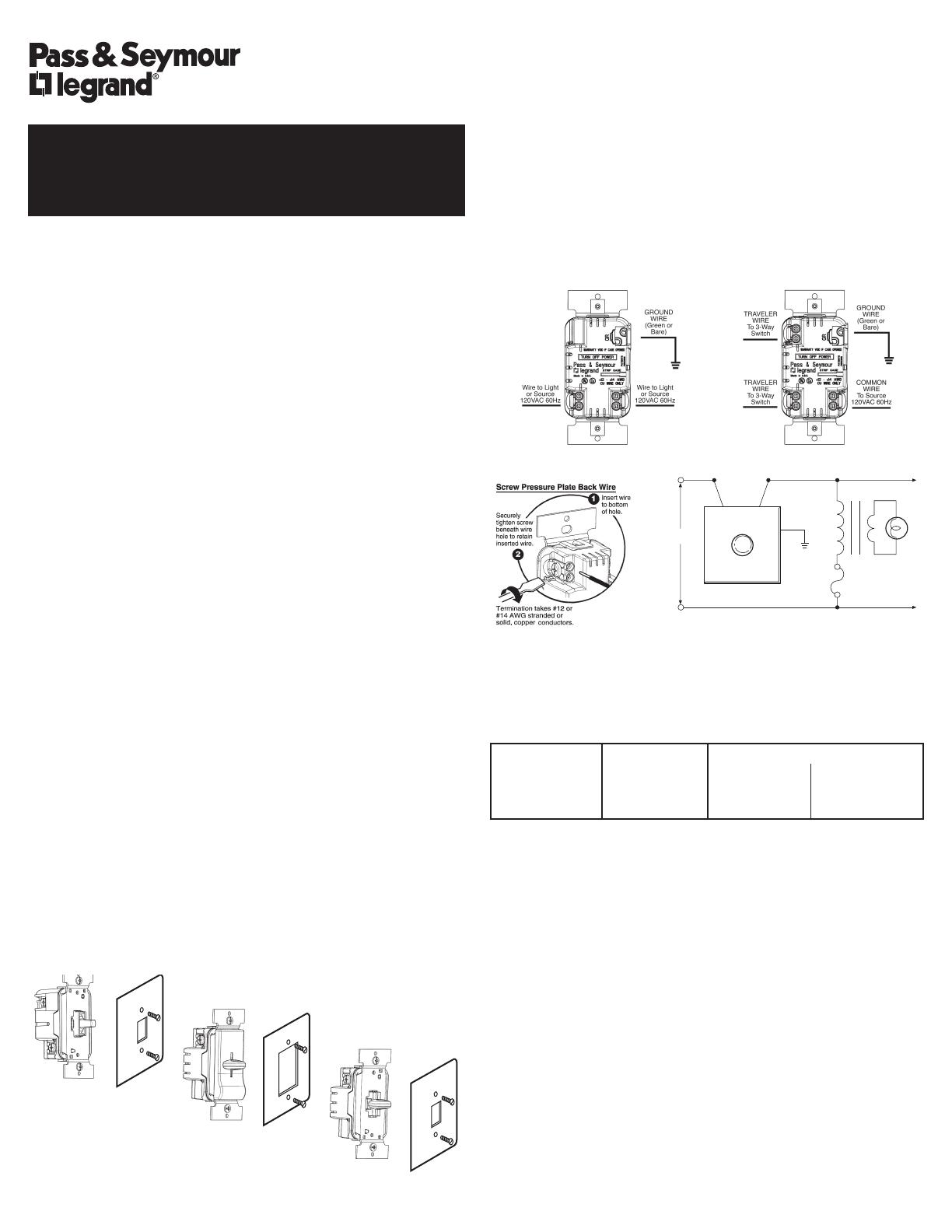
INSTALLATION DIAGRAM (wiring is same for each dimmer type)
MULTIPLE GANGING OF DIMMERS & OTHER DEVICES
Any combination of dimmer models and other devices may be ganged
together. Dimmers can be ganged without removing fins. De-rate the
maximum load according to the following table.
DIMMER
MAXIMUM
FINS REMOVED
RATING
LOAD
2 DIMMERS 3+DIMMERS
1000VA 800W 550W 500W
600VA 450W 400W 300W
WARRANTIES
Lifetime Warranty. The device you have purchased is warranted under normal
use against defects in workmanship and materials for as long as you own the
device. If the device fails due to manufacturing defect during normal use, return
the device for replacement to the store where purchased or send to:
Pass & Seymour Legrand
50 Boyd Avenue
Syracuse, NY 13209
All requests for replacement must include a dated sales receipt (legible copies
acceptable).
ALL OTHER WARRANTIES, INCLUDING BUT NOT LIMITED TO ANY
WARRANTIES OF MERCHANTABILITY OR FITNESS FOR A PARTICULAR
PURPOSE, ARE LIMITED TO A PERIOD OF TWO YEARS FROM THE
DATE OF PURCHASE. YOUR SOLE AND EXCLUSIVE REMEDY AGAINST
PASS & SEYMOUR LEGRAND UNDER ANY WARRANTY SHALL BE THE
EQUIVALENT REPLACEMENT OF THE DEVICE. IN NO EVENT SHALL ANY
WARRANTY APPLY TO ANY DEFECT ARISING OUT OF ANY ALTERATION
OF THE DEVICE, IMPROPER WIRING, IMPROPER INSTALLATION,
MISUSE, ABNORMAL USE OR NEGLIGENCE. IN NO EVENT SHALL PASS
& SEYMOUR LEGRAND BE LIABLE FOR LOST PROFITS, INDIRECT,
SPECIAL, EXEMPLARY, INCIDENTAL OR CONSEQUENTIAL DAMAGES.
Some states do not allow limitations on how long implied warranties last and
do not allow exclusion or limitation of incidental or consequential damages.
Some of the above limitations or exclusions may not apply to every purchaser.
INSTALLATION INSTRUCTIONS
TradeMaster
®
LOW VOLTAGE INCANDESCENT DIMMERS
READ AND SAVE THESE INSTRUCTIONS!
LAMPS
TO ADDITIONAL
TRANSFORMERS
BLACKBLACK
HOT
NEUTRAL
120
GREEN
TRANSFORMERS
(1)
(2)
GROUND
WIRE
(1) TRANSFORMER IS USUALLY PART OF THE FIXTURE.
(2) FUSE PROTECT EACH TRANSFORMER AS RECOMMENDED BY
TRANSFORMER MANUFACTURER.
Wiring Diagram
Toggle
Decorator Slide
Short Slide
To be installed by a certified electrician or other qualified person.
WARNING – To prevent severe shock or electrocution, always turn power
OFF at the service panel before installing this unit, working on the circuit, or
changing a lamp.
CAUTION – To reduce the risk of overheating and possible damage to
other equipment, do not install to control a receptacle, or a motor-operated
appliance. Connect dimmers only in a 120VAC, 60 Hz circuit to control the
primary of a transformer-supplied incandescent load. Maximum VA rating of
dimmer applies to transformer input, not load on the transformer secondary.
Do not use dimmer with incandescent lamps whose power requirements
exceeds maximum power (stated in Watts) of the dimmer.
Do not use to control a solid-state transformer.
Use copper wire only.
DIRECTIONS
1. Disconnect power to circuit at the panel by removing fuse or turn circuit
breakers OFF before installing.
2. Remove wall plate and switch mounting screws, pull existing switch from
wall box.
3. Disconnect existing switch from circuit. 3-Way Installation: Identify the
“COMMON” wire (wire connected to the terminal marked common or odd
colored terminal). For “new” installation identify wire connected to power
source or to the load.
4. Connect dimmer as shown in the installation diagram using #12 or #14
AWG stranded or solid copper conductors. Strip wire using gauge on back
of device.
5. Install dimmer in wall box, with word ‘TOP’ on the strap right side up, using
mounting screws provided.
6. Restore power. Dimmer may need to be adjusted to accommodate
low voltage transformer. To do this, DISCONNECT POWER FROM
CIRCUIT. Remove dimmer from wall box. Use a small, insulated flat-
tipped screwdriver to adjust trim pot located through access opening on
ground side of control. After adjusting, remount dimmer in wall box per
above instructions. Restore power and test. Repeat above as necessary.
Disconnect power again when adjustment is complete. NOTE: Never
adjust trim pot when circuit is live.
7. Attach wall plate, then restore power to circuit. NOTE: It is necessary to
remove knob on Short Slide version before attaching wall plate.
NOTE: It is normal for the dimmer to feel warm during operation. A 50W
minimum load is required. Use a separate neutral wire for each phase of a
multiphase system containing a dimmer, and for high power single phase
applications where flickering is present.
DIMMER TYPES
Single Pole Three Way

