Page is loading ...

No: 341160 5/16
WattStopper
®
radiant
®
Magnetic Low Voltage Dimmers: 700VA, 1100VA, 120VAC, 60Hz
Gradateurs magnétiques basse tension radiant
®
: 700 VA, 1100 VA, 120 VCA, 60 Hz
Atenuadores magnéticos de bajo voltaje radiant
®
: 700 VA, 1100 VA, 120 VCA, 60 Hz
Installation Instructions • Instrucciones de Instalación • Notice d’Installation
Catalog Number(s) • Numéro(s) de Catalogue • Les Numéros de Catalogue: RHLV703P, RHLV1103P
Country of Origin: Made in China • Pays d’origine: Fabriqué en Chine • País de origen: Hecho en China
These Dimmers are for use with Magnetic Low Voltage Incandescent and Halogen lamps.
IMPORTANT NOTES:
1. All dimmers can be damaged by improper wiring. Check for short circuits prior to installing the
dimmer.
Procedure for short circuit check:
a. Disconnect power to circuit by removing fuse or turn circuit breakers OFF.
b. Install a switch instead of the dimmer. Turn the switch to the “ON” position.
c. Turn power ON. If the circuit breaker trips, a short is present. If the light fails to turn ON and
OFF with the switch, the wiring may be incorrect.
d. Correct wiring, if necessary and retest.
e. Install the dimmer only after the light operates properly with the switch.
2. Protect from dirt and dust. The dimmer can be damaged from contam inates encountered during
the construction process. If lighting is required prior to the construction process completion, then a
switch should be temporarily installed in place of the dimmer. The dimmer should not be installed
until the construction process is complete.
Any dimmer damaged due to improper installation is not covered under warranty.
COLOR CHANGE PROCEDURE/PROCÉDURE DE CHANGEMENT DE COULEUR/
PROCEDIMIENTO DE CAMBIO DE COLOR
DIRECTIONS:
1. If a color change kit was provided, and a different color is desired, see the Color Change
Procedure, if not proceed to step #2.
2. Disconnect power to circuit by removing fuse or turn circuit breakers OFF before installing.
3. Remove wall plate and switch mounting screws, pull existing switch from wall box.
4. Disconnect existing switch from circuit. 3-way installation: Identify the “Common” wire (wire
connected to the terminal marked common or odd colored terminal). For new installation identify
wire connected to power source or to the load.
5. Connect dimmer as shown in the installation diagram using #12 or #14 AWG stranded or solid
copper conductors. Strip wire using gauge on back of device. (Figure 1)
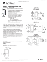
INSTALLATION DIAGRAM FOR DIMMERS / SCHÉMA D’INSTALLATION DES GRADATEURS
DIAGRAMA DE INSTALACIÓN PARA ATENUADOR
Single Pole/Unipolaire/Unipolar 3-Way/3 voies/3 vías
Figure 1/Figure 1/Figura 1
Screw Pressure Plate Back Wire
Fil arrière avec vis et plaque de pression
Cable trasero con tornillo y placa de presión
6. Install dimmer in wall box, with word “TOP” on the strap right side up, using mounting screws
provided.
7. Attach wall plate and then restore power to circuit.
8. Dimmer may need to be adjusted to accommodate low voltage transformer. To do this,
DISCONNECT POWER FROM CIRCUIT, and remove the Wallplate. Use a small insulated,
flat tipped screwd river to adjust the trim pot, which is accessible via the slot (marked
“CALIBRATION”) provided on the strap. (Figure 2) Turn down to increase the minimum light
intensity setting. Next, mount the Wallplate back, restore the power and test. Repeat above as
necessary. Note: Never adjust trim pot when circuit is live.
NOTE: It is normal for the dimmer to feel warm during operation. Use a separate neutral wire for
each phase of a multiphase system containing a dimmer, and for high power single phase
applications where flickering is present.
MULTIPLE GANGING OF DIMMERS AND OTHER DEVICES
Any combination of dimmer models and other devices may be ganged together. Break off tabs are
provided on the 1100VA dimmer straps for multi-gang applications. Pry off the tabs using pliers
before installation, as shown in figure 3. De-rate the maximum load according to the following table:
Dimmer Catalog # Maximum Load
Multi-Gang Derating
2 Gang Installation 3 Gang Installation
RHLV703P 700VA 700VA 650VA
RHLV1103P 1100VA 900VA 700VA
Figure 3: Multiple Ganging of Devices
Figure 3 : Groupement de plusieurs dispositifs
Figura 3: Instalación en grupo de múltiples dispositivos
READ AND SAVE THESE INSTRUCTIONS
To be installed by a certified electrician or other qualified
person.
WARNING – To prevent severe shock or electrocution,
always turn power off at the service panel before installing
this unit, working on the circuit, or changing a lamp.
CAUTION – To reduce the risk of overheating and possible
damage to other equipment, do not install to control a
receptacle, a fluorescent light or bulb or a motor-operated
appliance. The maximum VA rating of this dimmer applies
to the transformer input, not the load on the transformer
secondary.
• Do not use with inoperative or missing lamps. Use of this
dimmer with inoperative or missing lamps can create an
over current condition which may damage the transformer.
Use transformers that incorporate thermal protection of a
fuse at the primary windings.
• Connect only in a 120VAC, 60Hz circuit to control the
primary of a transformer supplied incandescent.
• A 50VA minimum load is required.
• Use copper wire only.
LIRE ET CONSERVER CES INSTRUCTIONS
Doit être installé par un électricien certifié ou une autre
personne qualifiée.
AVERTISSEMENT – Pour éviter tout choc électrique ou
une électrocution, toujours couper l’électricité au niveau
du panneau d’alimentation avant d’installer cette unité, de
travailler sur le circuit électrique ou de changer une lampe.
ATTENTION – Pour éviter toute surchauffe et endommage-
ment éventuel des autres appareils, ne pas utiliser pour
contrôler une prise, une lampe ou un tube fluorescent ou un
appareil ménager utilisant un moteur. La capacité en VA de
ce gradateur concerne l’entrée du transformateur, et non la
charge sur le secondaire du transformateur.
• Ne pas utiliser si des lampes manquent ou sont hors
service. L’utilisation de ce gradateur avec des lampes
hors service ou manquantes peut créer une surtension
qui peut endommager le transformateur. Utiliser des
transformateurs équipés d’une protection thermique ou
d’un fusible sur le bobinage primaire.
• Connecter uniquement sur un circuit 120 VCA, 60 Hz pour
contrôler le primaire d’un transformateur alimentant une
lampe à incandescence.
• Doit alimenter une charge de 50 VA minimum.
• N’utiliser que des fils en cuivre.
LEA Y CONSERVE ESTAS INSTRUCCIONES
Para ser instalado por un electricista certificado o persona
competente.
ADVERTENCIA – Para evitar descargas eléctricas serias
o electrocución, antes de instalar, trabajar en el circuito o
cambiar una lámpara de este atenuador apague siempre el
suministro eléctrico en el panel de servicio.
PRECAUCIÓN – Para reducir el riesgo de sobre calenta miento
y posibles daños a otros equipos, no instalar para controlar
un tomacorriente, una lámpara o bombilla fluorescente, o un
electrodoméstico con motor. La capacidad máxima en VA de
este atenuador se aplica a la entrada del transformador, no a
la carga en el devanado secundario del mismo.
• No utilice con lámparas fuera de servicio o faltantes.
La utilización de este atenuador con lámparas fuera
de servicio o faltantes puede crear una condición de
sobrecorriente que podría dañar al transformador. Utilice
transformadores que incorporen protección térmica de un
fusible en el devanado primario.
• Conecte únicamente en un circuito de 120VCA, 60Hz,
para controlar el primario de un transformador que
alimenta una lámpara incandescente.
• Se requiere una carga mínima de 50VA.
• Utilice únicamente alambres de cobre.
Remove all fins
Retirer toutes
les ailettes
Retirar todas
las lengüetas
Remove inside fins only
Retirer les ailettes
intérieures uniquement
Retirar lengüetas
internas solamente
2 GANG
INSTALLATION
CONFIGURATION
DOUBLE
CONFIGURACÍON
DOBLE
3 GANG
INSTALLATION
CONFIGURATION
TRIPLE
CONFIGURACÍON
TRIPLE
RHLV703P RHLV1103P
1.
2.
4.
5.
3.
6.
Traveler Wire to
3-Way Switch
Commun vers
l’interrupteur 3 voies
Alambre común
al interruptor
de 3 vías
1
Wire to Source
120VAC 60Hz
Raccorder à la source
120 VCA 60 Hz
Alambre de la fuente
120 VCA 60 Hz
2
Traveler Wire to
3-Way Switch
Commun vers
l’interrupteur 3 voies
Alambre común al
interruptor de 3 vías
3
Ground Wire
(Green or Bare)
Fil de Terre (vert ou nu)
Alambre de Tierra
(Verde o desnudo)
4
1
3
2
4
2
3
1
4
Wire to Light
120VAC 60Hz
Raccorder à la lampe
120 VCA 60 Hz
Alambre a
la lámpara
120 VCA 60 Hz
1
Wire to Light or Source
120VAC 60Hz
Raccorder à la lampe ou
à la source 120 VCA 60 Hz
Alambre a la lámpara
o de la fuente
120 VCA 60 Hz
2
Do not wire this terminal
Ne rien brancher
sur cette borne
No cablear
esta terminal
3
Ground Wire
(Green or Bare)
Fil de Terre (vert ou nu)
Alambre de Tierra
(Verde o desnudo)
4
Figure 2/Figure 2/Figura 2
/