
Rev. 1.0 (7/29/2014) www.amx.com
AMX AV/IT Administrators Guide
This document provides a technical overview of equipment and protocols encountered when
implementing AMX products on the Enterprise Network. The goal of this document is to help
AV/IT administrators during the buying process as they assess the network impact of
integrating AMX equipment.

AMX AV/IT Administrators Guide
Rev. 2.0 (9/4/2014) www.amx.com Page i
Contents
AMX Network Products ................................................................................................................................ 1
Central Controllers ................................................................................................................................ 1
Touch Panels ......................................................................................................................................... 2
Media .................................................................................................................................................... 2
Management ......................................................................................................................................... 2
Network Environment ................................................................................................................................... 3
Physical Network requirements ................................................................................................................ 3
DXLink vs. Ethernet ............................................................................................................................... 3
Wireless ................................................................................................................................................. 3
Logical Network Topology ......................................................................................................................... 3
VLAN ...................................................................................................................................................... 3
Addressing requirements .......................................................................................................................... 4
Security ......................................................................................................................................................... 5
Ports and Services ..................................................................................................................................... 5
Firewalls .................................................................................................................................................... 5
Access Control ........................................................................................................................................... 5
Passwords ................................................................................................................................................. 7
Security Modes ......................................................................................................................................... 8
Central Controller ................................................................................................................................. 8
Touch Panel ........................................................................................................................................... 9
Control over IP ............................................................................................................................................ 10
Internet Control System Protocol (ICSP) ................................................................................................. 11
Device Addressing ............................................................................................................................... 11
Ethernet Transport of ICSP ................................................................................................................. 12
Central Controller to Device connections ............................................................................................... 13
Communication Protocols and Network Impact .................................................................................... 14
Central Controller to Central Controller connections ............................................................................. 15
Central Controller to Central Controller Topology ................................................................................. 16
Dual Network Interfaces (NICs) .............................................................................................................. 17
Media .......................................................................................................................................................... 18
Digital Signage ......................................................................................................................................... 18

AMX AV/IT Administrators Guide
Rev. 2.0 (9/4/2014) www.amx.com Page ii
Network Impact ...................................................................................................................................... 18
Video Management and Distribution ......................................................................................................... 19
Vision2 ..................................................................................................................................................... 19
Video Streaming on IP Networks ............................................................................................................ 20
Multicast on enterprise networks ........................................................................................................... 21
Multicast Example ................................................................................................................................... 21
IGMP ................................................................................................................................................... 22
IGMP Snooping ................................................................................................................................... 23
PIM ...................................................................................................................................................... 23
PIM Sparse Mode (PIM-SM) ................................................................................................................ 24
Storm Control ...................................................................................................................................... 25
Management ............................................................................................................................................... 25
RMS Enterprise ....................................................................................................................................... 25
Scheduler ................................................................................................................................................ 26
Network Impacts ..................................................................................................................................... 26
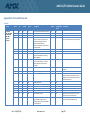
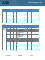
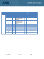
Appendix A Ports and Protocols ................................................................................................................. 27
Appendix B Default Values for AMX Products ............................................................................................ 32
Appendix C Operating systems ................................................................................................................... 36

AMX AV/IT Administrators Guide
Rev. 1.0 (4/10/2014) www.amx.com Page 1
AMX Network Products
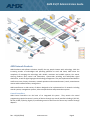
AMX hardware and software solutions simplify the way people interact with technology. With the
increasing number of technologies and operating platforms at work and home, AMX solves the
complexity of managing this technology with reliable, consistent and scalable systems. Our award-
winning products span control and automation, system-wide switching and audio/video signal
distribution, as well as digital signage and technology management. They are implemented worldwide in
conference rooms, homes, classrooms, network operation and command centers, hotels, entertainment
venues and broadcast facilities, among others
AMX manufactures a wide variety of devices designed to be implemented on IP networks including
control systems, management systems, video transport devices and presentation systems.
Central Controllers
AMX Central Controllers are the brain of an integrated AV system. They contain the central
programming required to control a variety of devices through any control interface including IP, RS-232,
RS-422, RS-485, IR, Relay, Digital I/O, and Analog control as well control of almost any interface through
adapters.

AMX AV/IT Administrators Guide
Rev. 2.0 (9/4/2014) www.amx.com Page 2
Central Controllers are available with a variety of control interfaces built into the controller or interfaces
may be connected through ICSLan devices over IP. The Enova DVX and Enova DGX series switchers
include a built in Central Controller within the chassis. In all cases the Central controller is a separate
logical device from the interfaces or switches.
Touch Panels
AMX Touch Panels are multifunction devices on the network. In addition to the primary function as a
control surface for the AV control system they have multiple other functions such as a video streaming
display, status monitor, scheduling interface, SIP telephony endpoint, VNC host/client, and Audio/Video
Intercom. The new G5 series of touch panels have the ability to run web apps including browsing and
videoconferencing.
Media
Vision2 is a sophisticated, fully-integrated video capture, management, and broadcast system for
organizations and homeowners wanting a comprehensive, yet simple-to-use, IP video delivery solution.
Vision2 offers live, scheduled, or on-demand video, all managed from a convenient web interface.
Through the web interface, you can perform the following:
Capture and encode content
Upload, archive, manage, and publish content
Schedule programming
Broadcast at selectable bitrate to any platform
Provide live TV and video on-demand over Intranet to PCs and Set-top boxes attached to
displays
Provide video on-demand to supported tablets
Management
AMX's Resource Management Suite (RMS) is designed for any integrated spaces where IT, AV and
facilities managers can benefit from a centralized remote management tool. By bringing together what
have traditionally been discreet systems into a single management environment it provides real-time
monitoring, device management, user behavior and energy utilization analytics. Utilizing this same
communication infrastructure it also provides a central integration point for communication with
external services such as scheduling systems and SNMP monitoring.
Rapid Project Maker (RPM) is a free cloud-based application which allows for semi-custom integration of
AMX control systems without the expense of custom programming. From a web interface, RPM steps
you through the process of configuring the control system to your specific equipment and application.
RPM then generates the program files for the controller and user interfaces as well installation
documentation including all cabling connections. Once you are happy with the design everything and be
downloaded for transfer to the AMX AV system. No internet connectivity to the AV system is ever
required. Configurations are stored on the cloud for easy configuration management which allows for
moves, additions, and changes to be quickly implemented, just by modifying the existing project to the
new feature. When new rooms are implemented in RPM, RMS code is automatically implemented to

AMX AV/IT Administrators Guide
Rev. 2.0 (9/4/2014) www.amx.com Page 3
bring the room into management. More information and account signup is available at
http://www.amxrpm.com.
Network Environment
Physical Network requirements
AMX AV and control equipment is designed to use the same switched Ethernet infrastructure as other IT
equipment. Considerations for bandwidth, VLANs, IP addressing scheme and PoE will be based on the
actual equipment and scope of the project as in any other IT installation. Most AMX devices have
10/100BaseT ports and are compliant with the IEEE 802.3 100BASE-T specification. The units, by default,
enters auto-negotiate mode, which automatically detects and configures itself for operation on the
network to which it’s connected. It is possible to force the mode of operation (10Mbps half, 10Mbps full,
100Mbps half, or 100Mbps full) via software configuration. Some AMX devices have DXLink
connections which are not directly connectable to an Ethernet switch.
DXLink vs. Ethernet
In some cases audio, video, network and control may be transported over DXLink. Although this is using
the same Cat6 cable as Ethernet and 100Mbps Ethernet can be tunneled through the cable along with
the other signals it is not Ethernet and never attaches directly to a switch or router. Equipment that is
connected over DXLink may also have an Ethernet jack for convenience in extending the control
network. DXLink products do not support Spanning Tree so only one connection to a LAN is permitted
within a switching system with DXLink support.
Wireless
AMX wireless touch panel are mobile devices that communicate with a NetLinx Central Controller via a
standard 802.11a/b/g Wireless Access Point. They support both simple and enterprise security modes
including password or certificate based authentication.
In a small system the control system can connect to a standalone access point, but in an enterprise with
managed wireless the best practice would be to assign a separate AV SSID routed to the AV subnet.
Using the existing engineered wireless plan and infrastructure will ensure that there is no RF
interference that could be caused by a separate Wireless Access Point.
Logical Network Topology
VLAN
Best practices dictate that AV equipment be separated from other network traffic. There are several key
strategies in segmenting traffic which drives this separation. The strategies and justification for
separating AV into a separate VLAN(s) follow.
Group devices by traffic patterns
o AMX equipment communicates primarily among the AV devices with limited
connectivity to the data network.

AMX AV/IT Administrators Guide
Rev. 2.0 (9/4/2014) www.amx.com Page 4
Group devices for security and safety
o There are limited valid reasons for remote access to the AMX equipment and the
equipment controls potentially sensitive meetings.
o AMX systems may control physical environments like projector lifts and lighting
Improper remote access could be a safety issue.
Group devices by traffic types
o AMX devices primarily communicate between each other using ICSP over IP.
o There is significant broadcast traffic between AMX devices
Group devices geographically
o In a campus setting, which may have multiple VLANs due to LAN topology requirements,
routing should be enabled between the control VLANs
AV Devices not on the control VLAN
In the case of devices with network connections that utilize the Ethernet connection for both
control and media, such as a VTC Codec or streaming encoder/decoder, the device should reside
on the VLAN that makes the most sense for the media, but a static route should be set to the
control network with an ACL to allow for traffic.
In the case of a management system such as RMS, the best practice would be to have the RMS
Server reside on the data network with a static route set to the control network with an access
control list (ACL) to allow for traffic to and from RMS.
Addressing requirements
AMX equipment supports DHCP and Static addressing with one IP address per device. AMX Central
Controllers do not act as a DHCP server.
Touch Panels and other peripheral devices register (bind) to the Central Controller so they need a
constant unique reference to the Central Controller.
This can be an IP address, either static or issued from a DHCP reservation. If DHCP without a
reservation is used then an alternative ID is used, DNS name, MAC address, or system number.
If MAC address or System Number is used then the Central Controller is required to send out a
Netlinx Discovery Protocol (NDP) Broadcast to let the peripherals know the IP address of the
Central Controller.
o MAC address and system number binding require the peripherals to be on the same
subnet as the Central Controller.
If DNS Binding is used then the DHCP server must support Option 81 DHCP host name update, or
static address assignments must be configured.
Touch Panels and other peripheral do not require a static IP address and can be configured with DHCP.
If advanced features of the touch panel are used such as VNC for virtual Touch Panel interfaces
then there may be an advantage to using a Static IP address or DNS records.

AMX AV/IT Administrators Guide
Rev. 2.0 (9/4/2014) www.amx.com Page 5
More information on binding requirements and impact is available in the Central Controller to Device
connections section of this document.
Security
Ports and Services
The AMX Central Controller features a number of standard services which are on by default. These
services can be individually disabled. The port assignments can be changed for all these services except
FTP. Assigning security profiles will disable some services. A complete list of Ports and Protocols used
across AMX Ethernet enabled products is in Appendix A.
Common Ports and Protocols Used (See Appendix A):
Telnet
Port 23
ICSP
Port 1319
HTTP
Port 80
HTTPS
Port 443
SSH
Port 22
FTP
Port 21
Firewalls
AMX control systems are not required to have internet access to function. There are advanced
applications which may require internet access. For example;
RMS Enterprise Hosted Cloud Service which will require a HTTP access to the hosted service
Individual applications on products such as digital signage which require access to external
content sources such as XML or RSS feeds.
TPControl app for mobile devices
RMS Enterprise Hosted Cloud Service and applications which require external content will always initiate
a data exchange from inside the firewall. External control such as the TPControl app requires an
externally routable IP address on the Central Controller on port 1319. Ports and protocols for all
standard data communications on AMX products are found in Appendix A.
Access Control
AMX Central Controllers allow for multiple user accounts. These accounts should be set up using the
least privilege strategy. This means that privileges are not granted unless necessary and not used unless
intended. The requirement to use role based access control helps to reduce the complexity and
potential errors associated with privileged account maintenance. Accounts may be created individually
on each Central Controller or centrally in an LDAP Server. For more information on access control see
http://www.amx.com/assets/manuals/NetLinxControllers.WebConsole-ProgrammingGuide.FMv4.pdf .
AMX Central Controller security allows the Administrator to define access rights for users or groups. A
user represents a single potential client of the system while a group represents a logical collection of

AMX AV/IT Administrators Guide
Rev. 2.0 (9/4/2014) www.amx.com Page 6
users. Any properties possessed by groups (i.e., access rights, directory associations, etc.) are inherited
by all the members of the group.
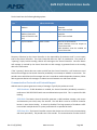
The following table lists the features the Administrator may grant or deny access to:
System Security Features:
Central Controller Security Configuration
Access to the security configuration command
of the Enova DVX central controller (Central
Controller). Only those users with security
configuration access rights granted will have
access to the security configuration commands.
Telnet Security
Access to the device’s Telnet interface. All
basic commands are available to the user.
Terminal (RS-232) Security
Access to the Terminal Interface (Program
Port) functionality through the RS-232
connector. All basic commands are available to
the Site Administrator.
HTTP (Web Server) Security
Access to the HTTP server functionality.
Directory associations assign specific
directories/files to a particular user.
FTP Security
Access to the FTP server functionality. Only the
Administrator account has access to the root
directory; all other ‘qualified’ clients are
restricted to the /user/ directory and its ‘tree.’
ICSP
Access to the ICSP communication
functionality. Communication and encryption
rights are available to an authorized user.
ICSP Encryption
The access to the ICSP data encryption
functionality. Enabling encryption of ICSP data
requires that both:
AMX hardware or software
communicating with the target Enova
DVX central controller (Central
Controller) provide a valid username
and password.
All communication is encrypted.

AMX AV/IT Administrators Guide
Rev. 2.0 (9/4/2014) www.amx.com Page 7
In a typical secure setup there will be 3 User Groups
1. Super Admin
a. All Admin rights including password and configuration changes
1) Terminal <RS232> Access ............................... Enabled
2) Admin Change Password Access..................... Enabled
3) FTP Access ...................................................... Optional
4) HTTP Access .................................................... Optional
5) Telnet/SSH/SFTP Access ................................. Optional
6) Configuration Access ...................................... Enabled
7) ICSP Access...................................................... Enabled
8) ICSP Encryption Required ............................... Optional
2. Log Admin
a. Able to view system settings and access logs
1) Terminal <RS232> Access ............................... Enabled
2) Admin Change Password Access..................... Disabled
3) FTP Access ....................................................... Disabled
4) HTTP Access .................................................... Disabled
5) Telnet/SSH/SFTP Access ................................. Disabled
6) Configuration Access ...................................... Disabled
7) ICSP Access...................................................... Disabled
8) ICSP Encryption Required ............................... Optional
3. Touch Panel / ICSLan device
a. Each Touch Panel or ICSLan device should have a separate user account
b. User setup for touch panel control
1) Terminal <RS232> Access ............................... Disabled
2) Admin Change Password Access..................... Disabled
3) FTP Access ....................................................... Disabled
4) HTTP Access .................................................... Disabled
5) Telnet/SSH/SFTP Access ................................. Disabled
6) Configuration Access ...................................... Disabled
7) ICSP Access...................................................... Enabled
8) ICSP Encryption Required ............................... Enabled
Passwords
AMX components ship with well-known default passwords. Passwords should be changed from the
default.
Default Passwords and settings are listed in Appendix B

AMX AV/IT Administrators Guide
Rev. 2.0 (9/4/2014) www.amx.com Page 8
Security Modes
Central Controller
By default the AMX controller and Touch Panels are in an unsecured mode allowing Telnet and http
access.
There are three levels of security for the Enova DVX; Low, Medium, and High. The features for
each mode are described as follows:
Low Security Mode:
o Factory default, shipped in this configuration.
o Administrator and User accounts have a default password of “password.”
o Telnet, HTTP, HTTPS, SSH are all enabled and require no authentication.
o ‘Program Ports’ terminal configuration access requires no authentication.
o ICSP communication protocol between devices: encryption and authentication
are disabled.
o FTP is enabled.
o Minimum password requirements are 8 characters.
Medium Security Mode:
o Provisioning is done through a terminal session from an on-site workstation that is
connected with an RS-232 cable to the ‘Program Port’ on the Enova DVX.
o Site Administrator password is default to “Amx1234!”
o HTTP, Telnet, and FTP are disabled.
o SSH, HTTPS, and accessing the ‘Program Port’ for a terminal session requires
authentication by the Site Administrator.
o SSH, HTTPS, and terminal session timeouts are enabled.
o ICSP communication protocol between devices has encryption and authentication
enabled.
o Minimum password requirement is 15 characters such that:
The password contains at least on uppercase alphabetic character.
The password contains at least one lowercase alphabetic character.
The password contains at least one numeric character.
The password contains at least one special character.
The password does not contain more than three consecutive repeating
characters.
o Login failure attempt pauses 4 seconds before another login attempt is allowed.

AMX AV/IT Administrators Guide
Rev. 2.0 (9/4/2014) www.amx.com Page 9
o After three consecutive unsuccessful login attempts, login lockout is enabled for
10 minutes.
o Login and logout audit logging is enabled.
o All existing user accounts are deleted to ensure password conformity.
High Security Mode:
o Provisioning is done through a terminal session from an on-site workstation that is
connected with an RS-232 cable to the ‘Program Port’ on the Enova DVX.
o Site Administrator password is default to “Amx1234!”
o HTTP, Telnet, SSH, HTTPS, and FTP are disabled.
o ICSP communication protocol between devices has encryption and authentication
enabled.
The AMX Central Controller security allows the Site Administrator to define access rights for users
or groups. A user represents a single potential client of the system while a group represents a
logical collection of users. Any properties possessed by groups (i.e., access rights, directory
associations, etc.) are inherited by all the members of the group.
Touch Panel
There are three levels of security for the Modero X Touch Panel; Low, Medium, and High. The feature
set for each mode is described as follows:
Low Security Mode:
o Factory default, shipped in this configuration.
o Administrator and User accounts have a default password of “1988.”
o Telnet and G4 web control are all enabled and require no authentication.
o Telnet session timeouts are enabled.
o Minimum password requirements are 8 characters.
Medium Security Mode:
o Provisioning is done through a protected setup page on the Modero X touch panel.
o Site Administrator password is default to “Amx1234!”
o Telnet is disabled.
o Remote access via SSH requires authentication by the Site Administrator (SSH
username is ‘amx.’
o SSH session timeouts are enabled.
o G4 Web Control is disabled.
o Minimum password requirement is 15 characters such that:
The password contains at least on uppercase alphabetic character.

AMX AV/IT Administrators Guide
Rev. 2.0 (9/4/2014) www.amx.com Page 10
The password contains at least one lowercase alphabetic character.
The password contains at least one numeric character.
The password contains at least one special character.
The password does not contain more than three consecutive repeating
characters.
o Login failure attempt pauses 4 seconds before another login attempt is allowed.
o After three consecutive unsuccessful login attempts, login lockout is enabled for 10
minutes.
o Login and logout audit logging is enabled.
High Security Mode:
o Provisioning is done through a protected setup page on the Modero X touch panel.
o Site Administrator password is default to “Amx1234!”
o Telnet and SSH are disabled.
o SSH is disabled through a manual process.
o G4 Web Control is disabled
o Minimum password requirement is 15 characters such that:
The password contains at least on uppercase alphabetic character.
The password contains at least one lowercase alphabetic character.
The password contains at least one numeric character.
The password contains at least one special character.
The password does not contain more than three consecutive repeating
characters.
o Login failure attempt pauses 4 seconds before another login attempt is allowed.
o After three consecutive unsuccessful login attempts, login lockout is enabled for 10
minutes.
o Login and logout audit logging is enabled.
Control over IP
From a control perspective there are two classes of logical AMX devices, Central Controllers and devices.
Central Controllers run the software and control communications. Devices are the interfaces to the
equipment being controlled. A Central Controller will generally have devices within the same chassis,
but they are logically treated separately from the Central Controller.
AMX uses several standard protocols which are well documented elsewhere. AMX’s proprietary
Internet Control System Protocol (ICSP) and its methodologies will be discussed here.

AMX AV/IT Administrators Guide
Rev. 2.0 (9/4/2014) www.amx.com Page 11
Internet Control System Protocol (ICSP)
AMX devices communicate with each other using a proprietary low level protocol called Internet Control
System Protocol (ICSP). This protocol can be carried over the Ethernet TCP/IP connection, RS232 PPP
connection, and ICSNet connection to devices. ICSP is routable within AMX devices independent of
transport medium. Each ICSP client device is logically bound to a single Central Controller. If a second
Central Controller need to communicate with a client device the ICSP communication is sent to the
Central Controller the device is bound to and it is relayed to the client device through a Central
Controller to Central Controller (M2M) connection.
ICSP may also be encrypted where required by the environment. Encrypted ICSP uses a Challenge-
Handshake Authentication Protocol (CHAP) with a three way handshake using the MD5 hash algorithm.
The encryption is ARC4 with a commonly derived key, with no key information is passed between the
hosts. The entire ICSP packet, including headers, is encrypted and the resulting data encapsulated in a
new eICSP packet.
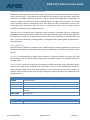
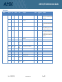
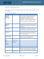
Device Addressing
Each ICSP Device, regardless of transport type is addressed with a unique combination of System and
Device with sub-addresses within Devices termed Ports. Addressing is specified as Device:Port:System
(D:P:S)
System ID is associated with a logical Central Controller (1 Central Controller per System ID). Valid
System numbers are 1 to 65535 and are unique within the network. System 0 is a wildcard referring to
the local system
Device Number is bound to a single Central Controller (multiple Devices per Central Controller). Device
numbers are unique within the System they are bound to. There is a limit of 200 devices bound to a
single controller. Many devices have range limitations on the device number that may be used. If an
incorrect device number outside of that range is assigned to a particular device, the module may not
function properly.
Physical Device Numbers
1-32000
Physical Devices
1-255
Access or AxLink devices
5001
Traditional device number for the NetLinx Integrated Device
5002
Traditional device number for the NetLinx Integrated Switcher
6001-6999
Traditional device numbers for ICSNet and ICSLan devices, including DXLink TX
and RXs
10001-32000
Touch panels
Dynamically Assigned Device Numbers
32001-32767
Dynamically assigned device numbers

AMX AV/IT Administrators Guide
Rev. 2.0 (9/4/2014) www.amx.com Page 12
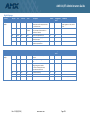
Virtual Device Numbers
32768-42000
Virtual Devices
32768-36964
User defined virtual devices
36865-37864
Dynamic Virtual Devices
37865-40999
NetLinx Module Virtual Devices
41000-42000
Duet Module Virtual Devices
Numbers
Ports are interfaces within a device (multiple ports per device) The number of ports depends on the
device.
Ethernet Transport of ICSP
In Ethernet transport ICSP packets are encapsulated in the data payload and forwarded from and to port
1319. All ICSP packets are forwarded over IP based on the ICSP Routing table. At each ICSP hop point
the ICSP packet is completely de-encapsulated and forwarded. No previous IP information (header,
source, etc.) is forwarded with the ICSP packet.
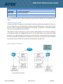
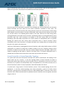
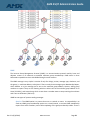
ICSP packets tunneled over Ethernet may follow a logical topology different from the physical topology.
In the diagrams below the highlighted EXB-Com2 is on the same subnet as the System #7 Central
Controller, but is logically bound to the System #1 Central Controller. Communication from the System
#7 Central Controller to the EXB-Com2 D:P:S (5101:1:1) will travel from the System #7 Central Controller
to the System #1 Central Controller and then will be forwarded to the EXB-Com2
Ethernet Physical Connection

AMX AV/IT Administrators Guide
Rev. 2.0 (9/4/2014) www.amx.com Page 13
ICSP Logical Connection
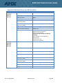
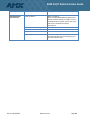
Central Controller to Device connections
AMX Devices other than Touch Panels are logically bound to an individual Central Controller in one of
four modes. The type of binding used will depend on network topology, IP address distribution strategy,
and DNS local host resolution
Binding
Type
Central Controller
Unique Identification
Central Controller
Address distribution
Notes
NDP
MAC Address
DHCP or Static
Must be on same Subnet
NDP Broadcast must be enabled on
Central Controller
UDP/URL
IP Address
Static or DHCP/DNS
For use on AMX only Networks
DHCP must use DNS
TCP/URL
IP Address
Static or DHCP/DNS
For use on Mixed AMX and Data
Networks
DHCP must use DNS
Auto
System Number
DHCP or Static
Must be on same Subnet
System Numbers must be unique to
Central Controller
NDP Broadcast must be enabled on
Central Controller

AMX AV/IT Administrators Guide
Rev. 2.0 (9/4/2014) www.amx.com Page 14
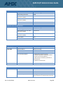
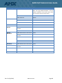
Touch Panels have the following binding options:
Binding
Type
Unique Identification
Central Controller
Address distribution
Notes
URL
Central Controller IP
Address
Static or DHCP/DNS
For use on Mixed AMX and Data
Networks
DHCP must use DNS
Listen
Touch Panel IP
Address (entered in
Central Controller URL
List)
Static or DHCP/DNS
For use on Mixed AMX and Data
Networks
DHCP must use DNS
Auto
System Number
DHCP or Static
Must be on same Subnet
System Numbers must be unique to
Central Controller
NDP Broadcast must be enabled on
Central Controller
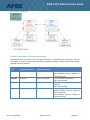
Discovery of devices by the Central Controller is the responsibility of the device itself—it must report
itself to the Central Controller. The Central Controller does not “poll” for new devices. The process of
“reporting” simply involves sending a Device Info message to the Central Controller. Once the Device
Info message is received by the Central Controller an ACK message is generated back to the sending
device for confirmation.
If the “reporting” device does not receive an ACK from the Central Controller, it will continue to send
Device Info messages to the Central Controller periodically in an attempt to establish a connection. The
periodic rate at which Device Info messages are sent is somewhat medium dependent, however, ICSNet
devices generate Device Info messages at random intervals between one and three seconds.
Communication Protocols and Network Impact
AMX AV control systems generate a variety of messages. Typically the packets are small
NDP Broadcast: If NDP Broadcast is enabled, the Central Controller periodically transmits a
multicast on 239.255.250.251 with source and destination port 1319. This is required for NDP
binding.
ICSP Blink: The NetLinx Central Controller generates a UDP broadcast message, with source
and destination port 1319, every five seconds. The ICSP Blink is used as a Central Controller
beacon in auto device binding. It cannot be disabled. The large quantity of broadcast traffic
incurred with multiple devices is a prime justification for a separate AV VLAN.
ICSP Keep alive: The Central Controller ensures that devices are still on-line by communicating
with them periodically. The periodic rate is five seconds. This communication can take the form

AMX AV/IT Administrators Guide
Rev. 2.0 (9/4/2014) www.amx.com Page 15
of any ICSP message that is specifically directed to/from that device (i.e. this does not include
broadcast messages).
For most devices the amount of ICSP communication is minimal and only occurs in response to user
input-which is, relatively speaking, very infrequent. During these quiescent times, the Central Controller
will generate a keepalive Request every five seconds to determine if the device is still on-line. The device
must respond to keepalive requests with a keepalive response messages. The Central Controller sends a
29 byte TCP or UDP unicast message, depending on binding, with source and destination port 1319, to
each bound device every 5 seconds. Devices respond with a 40 byte message.
Zero Config: If the Central Controller does not have an IP address that is assigned to it, then zero
configuration networking uses link-local addressing to create an IP address in a range from 169.254.1.0
to 169.254.254.25. When an IP address is chosen, the link-local process sends out a query with that IP
address onto the network to check whether the IP address is already in use. If there is no response, the
IP address is then assigned to the Central Controller. This can be disabled
NetLinx Events: An "event" in NetLinx is defined as a button press on a user interface, a level value
change, or other control message. By their nature, control messages are relatively short and infrequent.
For example, a button press message is 33 bytes long…for each button press event there is a
corresponding button release event that occurs (also 33 bytes long). An event is a unicast message in
either direction between a device and the Central Controller with source and destination port 1319.
Other Protocol Messages: Network packets may come from other application protocols. HTTP, FTP,
and Telnet protocols are well understood and the full implications, with respect to network utilization,
of their usage are not covered by this document. However, they require interaction with a user and,
therefore, their network utilization is very sporadic.
Central Controller to Central Controller connections
In an enterprise system it is often desirable to have control of remote devices bound to other Central
Controllers. AMX facilitates this through Central Controller to Central Controller (CC2CC)
communications. This is sometimes called “Master to Master (M2M)” communications referring to
legacy devices.
By design, all NetLinx Central Controllers do not automatically make a CC2CC connection with other
NetLinx Central Controllers by virtue of being on the same network. The connection between them must
be made intentionally by adding them to a list. This connection list is called the “URL List”. The URL List
can have a maximum of 250 connections. The URL List on the NetLinx Central Controller is used to force
the Central Controller to initiate a TCP connection to the specified URL/IP address. Therefore, the first
step in assembling a CC2CC system is to set unique system numbers on each Central Controller. Valid
system numbers are 1 to 65535, system 0 is a wildcard referring to the local system. The next step is to
configure the URL List in either of the Central Controllers, but not both, to point to the other Central
Controller. For example, in Illustration 1 NetLinx Central Controller system #1 could have its URL List
configured with a single entry that contains the IP address of the NetLinx Central Controller system #7;
this will establish a two-way connection. The system #7 Central Controller does not need to have a URL

AMX AV/IT Administrators Guide
Rev. 2.0 (9/4/2014) www.amx.com Page 16
entry to communicate with system #1. If the system #7 Central Controller’s URL List does contain the IP
address for system #1 a relay loop will be created which will lead to problems.
Once the systems are connected to each other they exchange ICSP routing information such that each
Central Controller will learn about all the Central Controllers connected to each other. The
implementation of Central Controller ICSP routing primarily involves the communication of ICSP routing
tables between Central Controllers. The ICSP routing table is built using the entries within the local URL
List, the DPS entries in the DEFINE_DEVICE section of the code, and from the ICSP routing tables
exchanged between connected Central Controllers. ICSP Routing tables are exchanged between Central
Controllers upon their initial connection and updates to the ICSP routing tables are exchanged
periodically. ICSP route table transmission has a certain amount of randomization built in to prevent
flooding the network with ICSP routing table transmissions when a Central Controller reports
online/offline. Each Central Controller in a network will add a minor random delay (1-5 seconds) so that
they don’t all transmit at the same time.
*Note: Any TCP/IP devices, including NetLinx Central Controllers, which utilize DHCP to obtain its TCP/IP
configuration, are subject to having their IP address change at any time. Therefore, NetLinx Central
Controller’s IP address must be static unless the network supports Dynamic DNS AND a DHCP server
capable of updating the DNS tables on behalf of the DHCP client. If a Dynamic DNS/DHCP server is
available then the NetLinx Central Controller’s host name may be used in the URL List.
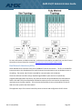
Central Controller to Central Controller Topology
In a system with more than two Central Controllers who need to communicate, the topology of the
logical routes may be a concern. In the Star Topology below if Central Controller #2 needs to
communicate with a device bound to Central Controller #3, then a ICSP packet is sent over IP to Central
Controller #1, the packet is de-encapsulated, read, re-encapsulated in an IP Packet and then sent to
Central Controller #3, where it is de-encapsulated, read and forwarded to the device.
In systems with a large amount of control between systems a fully meshed topology may be more
appropriate. In the fully meshed topology each Central Controller is aware of all other Central
Controllers. Routing loops are avoided by the use of a “ROUTE MODE DIRECT” command in each Central
Controller which allows communication only between Central Controllers who are logically connected
using the URL List.

AMX AV/IT Administrators Guide
Rev. 2.0 (9/4/2014) www.amx.com Page 17
For more information on M2M connectivity, architecture and scalability see AMX Tech note 919 “Central
Controller-to-Central Controller Unveiled” http://www.amx.com/techsupport/PDFs/919.pdf
Dual Network Interfaces (NICs)
Some AMX NX-Series controllers have two 10/100BaseT Ethernet connections. The first is intended for
interconnection to the Data Network for external network communications such as database access or
scheduling. The second, the ICS LAN is intended for communication with AV devices.
These two Ethernet interfaces occupy separate logical address space and act as a specifically
programmable Application Layer Relay. Any data that needs to be passed between the Data Network
and the ICS LAN is fully de-encapsulated, validated as required and re-sent based on the application
requirements to the other network. This minimizes the possibility that any vulnerabilities on the ICS
LAN can create a path to the data network.
The application layer of the central controller proxies all control and configuration of ISCP clients.
Page is loading ...
Page is loading ...
Page is loading ...
Page is loading ...
Page is loading ...
Page is loading ...
Page is loading ...
Page is loading ...
Page is loading ...
Page is loading ...
Page is loading ...
Page is loading ...
Page is loading ...
Page is loading ...
Page is loading ...
Page is loading ...
Page is loading ...
Page is loading ...
Page is loading ...
Page is loading ...
-
 1
1
-
 2
2
-
 3
3
-
 4
4
-
 5
5
-
 6
6
-
 7
7
-
 8
8
-
 9
9
-
 10
10
-
 11
11
-
 12
12
-
 13
13
-
 14
14
-
 15
15
-
 16
16
-
 17
17
-
 18
18
-
 19
19
-
 20
20
-
 21
21
-
 22
22
-
 23
23
-
 24
24
-
 25
25
-
 26
26
-
 27
27
-
 28
28
-
 29
29
-
 30
30
-
 31
31
-
 32
32
-
 33
33
-
 34
34
-
 35
35
-
 36
36
-
 37
37
-
 38
38
-
 39
39
-
 40
40


Ask a question and I''ll find the answer in the document
Finding information in a document is now easier with AI
Related papers
-
AMX NCITE-813 User manual
-
-
-
AMX RMS Interface for Lotus Datasheet
-
AMX DGX-I-DXF-SMS User manual
-
-
AMX SWM-V2 Specification
-
-
AMX DGX800/1600/3200-CPU Hardware Reference Manual
-
Other documents
-
MiLAN MIL-SME801P Release note
-
-
Dlink DVX-1000 Owner's manual
-
KEY DIGITAL APP READY Source and Display Control User manual
-
Itel VISION2 User manual
-
D-Link DVX-7090 User manual
-
Extron electronics VNE 200 DVI User manual
-
Cobalt Digital 9990-ENC-H264-IP HD/SD-SDI/CVBS H.264 Encoder User manual
-
ICT Protege GX System User guide
-
Philips BS01113 User guide