Page is loading ...

Instructions for Converting Range to Operate on Liquefied Petroleum Gas
INSTALLATION AND SERVICES MUST BE PERFORMED BY A QUALIFIED INSTALLER
IMPORTANT: SAVE INSTRUCTION MANUAL FOR THE LOCAL INSPECTOR’S USE.
READ AND SAVE THESE INSTRUCTIONS FOR FUTURE REFERENCE
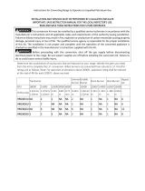
Determine the combination of top burners that are featured on your range. Identify the parts you need from this
kit to complete the L.P. conversion. When burners are converted from natural to L.P. the BTU ratings are as
follows: Note: For operation at elevations above 2000ft., appliance rating shall be reduced at the rate of 4% for
each 1000 ft. above sea level.
*LP Joint Compound (Pipe Dope) is needed for All LP Orifices installation, or a Potential Gas Leak might occur.
Top (from Left to Right): Orifice for Oven Burner / Oven Broiler Burner
Middle: 18,000 BTU Top Burner Orifice (2 pcs)
Bottom (from Left to Right): 12,000 BTU Top Burner Orifice (2 pcs), 9,000 BTU Top Burner Orifice (2 pcs)
Top Burner
Simmer
burner
Griddle
Burner
Oven Burner
Broil Burner
Bypass
Jet
BTU
18000
12000
9000
18500
10000
Orifice
Size(mm)
1.24
1.00
0.88
1.12
0.9
LRG3601U
2
2
2
NA
NA
NA
NA
1
NA
1
NA
0
This conversion kit must be installed by a qualified service technician in accordance with the
manufacturer's instructions and all applicable codes and requirements of the authority having jurisdiction.
Failure to follow instructions may result in fire, explosion or production of carbon monoxide causing property
damage, personal injury or loss of life. The qualified service agency is responsible for the proper installation
of this kit. The installation is not proper and complete until the operation of the converted appliance is
checked as specified in the manufacturer's instructions supplied with this kit.
Before proceeding with the conversion, shut off the gas supply before disconnecting
electrical power to the range. Be sure power supplies are off before installing the conversion kit. Failure to
do so could cause serious bodily injury.

Instructions for Converting Range to Operate on Liquefied Petroleum Gas
IMPORTANT: After replacing the natural gas to LP orifices, be sure to keep the original factory installed natural gas
orifices for future range conversion back to natural gas.
Tools for LP Conversion
7mm Tool – Top Burner Orifice Replacement
Flat Screw Driver ¢2.0*130 (Not Available with the LP Conversion Kit Package) – Bypass Adjustment
Adjustable Wrench *2 (Not Available with the LP Conversion Kit Package) – Orifice Adjustment
LRG3601U LP Conversion
1. Convert the Pressure Regulator
Locate the regulator on the back left of the range’s back panel.
**IMPORTANT** Be aware that there’s a difference on regulator cap position between NG and LP. All the gas
ranges are initially manufactured with regulator cap on NG position, please reverse the cap for LP conversion.

Instructions for Converting Range to Operate on Liquefied Petroleum Gas
2.Convert Top Burner for LP/ Propane Gas
Save the natural gas orifices removed from the appliance for possible future conversions to natural gas. You
should rely on the following process when converting unit back to Nature gas. Take extra care when handling
orifice parts, making sure the orifice is not
a. Remove top grates, burner caps and inner burner rings.
b. Lift off outer burner heads and burner bases.
c. Remove the factory installed natural gas orifices from the center of the orifice holders using a 7mm nut driver
Remember to keep the original natural gas orifices for future conversions back to natural gas.
“IMPORTANT” to identify their markings.
c.1. Replace the 18000BTU burner orifice in each with orifice size 1.24 mm.
c.2 Replace the 12000BTU burner orifice in each with orifice size 1.00 mm. Please remember not to over tighten
the orifice and keep the orifice clean.
c.3 Replace the 9000BTU burner orifice in each with orifice size 0.88 mm. Please remember not to over tighten
the orifice and keep the orifice clean.
Put the burner flame ring back to the main burner bases. Put back the inner burner rings, burner caps and grates.

Instructions for Converting Range to Operate on Liquefied Petroleum Gas
3. Convert Oven Bake Burner Orifice for LP/Propane Gas
a. Bake orifice will be exchanged from the front of the unit.
b. Take out the door of the range, and then take out the oven rack and the oven floor cover. Locate the bake
burner (L-shape burner) on the bottom of the unit. Screw out the two screws on the back of the bake burner, and
one on the front. Screw out the two screws connecting the bake ignitor to the bake burner;

Instructions for Converting Range to Operate on Liquefied Petroleum Gas
c. You will then see the orifice coming into the bake burner. Remove the orifice using an adjustable wrench.
There’s an aluminum pipe connecting safety valve and orifice, be careful so that you won’t break the pipe.
d. Use adjustable wrench to lose the orifice nut with the orifice, then screw out the screws on the bracket so that
you could get access to the orifice, at last screw out the orifice and replace with the LP Bake Orifice (1.12mm).
e. Make sure the bake burner it put back correctly. Make sure the orifice must be dead center of the burner or it
will create a vortex.
4. Covert Broil Burner Orifice
a. Broiler Burner is connected to Flame Tamer; b. Two screws on the back holding the burner to back oven panel;
c. One screw on the front holding the broiler burner; d. Lose the four screws on flame tamer to get access to broiler
orifice.

Instructions for Converting Range to Operate on Liquefied Petroleum Gas
a. The Back panel is not needed to be take out, broiler orifice will be exchanged from the front of the unit.
b. Locate the screws connecting the top broiler L-shape burner, there’re two on the oven back panel and on the
front of the broiler L-shape burner. Take out these three screws, hold the broiler burner to make sure it’s not
falling. Screw out the four screws holding the flame tamer so that the burner could be taken out and the broiler
orifice is accessible.
c. You will then see the orifice coming into the bake burner. Remove the orifice using an adjustable wrench.
There’s an aluminum pipe connecting safety valve and orifice, be careful so that you won’t break the pipe.
d. Use adjustable wrench to lose the orifice nut with the orifice, then screw out the screws on the bracket so that
you could get access to the orifice, at last screw out the orifice and replace with the LP Bake Orifice (0.9mm).
e. Make sure the bake burner it put back correctly. Make sure the orifice must be dead center of the burner or it
will create a vortex.
5. Convert Burner Valves for LP/Propane Gas
One 5/64” flat screw driver is needed for the Bypass Adjustment on Buner Valve (Not included in LPK Package),
a. Please take out the top burner knobs and take out the bezel and the screws on the bezel so that we could get
access to the burner valve part. You could get access to the burner valve part.
There’s a hole on the micro-switch (the black part) so that the screw driver could go across the micro-switch and
reach the bypass orifice on the burner valve. Bypass orifice could help to control the flame.

Instructions for Converting Range to Operate on Liquefied Petroleum Gas
s
b. Put the knob back, adjust the flame by rotating the knob. The original location of bypass is for NG. If converted
to LP, the bypass needs to be screwed in (in clockwise direction) to tightest position.
Originally, the Bypass is located at NG Position and it’s not screwed to the bottom (tightest)
For LP conversion of bypass, not bypass orifice needs to be changed.
Screw the Bypass Orifice to bottom (clockwise).
c. Save the main bypass jets, in the plastic bag labeled main jets and simmer bypass jets in the bag for simmer
jets.
When you are using your top burners, if the flame needs to be adjusted accordingly to fit your need, please adjust
the bypass orifices on the burner valve.
Put back the knob on and adjust the flame by rotating the bypass via a small flat screw driver. Check the flame’s
condition to get the best performance.
6. Reconnect Gas and Electrical Supply to Range.
Leak testing of the appliance shall be conducted according to the installation instructions provided with the range.
Checking for Manifold Gas Pressure
If it is necessary to check the manifold gas pressure, remove the burner cap, inner ring, outer burner head and
burner base of the right front top burner and connect a manometer (water gauge) or another pressure test
device to the burner orifice. Use a rubber hose with inside diameter of approximately ¼” and hold the end of the
tube tight over the orifice. Turn the gas valve on. For a more accurate pressure check, have at least two other top
burners burning. Be sure that the gas supply (inlet) pressure is at least one inch above the specified manifold
pressure. The gas supply pressure should never be over 14” water column. When properly adjusted the manifold
water column pressure is 10” for LP/Propane gas or 5” for Natural Gas.
7. Installation of New LP / Propane Rating / Serial Plate
Record the model and serial number on the LP / Propane Rating serial plate provided in this kit. The information
can be obtained from the existing Rating / Serial plate. Place the new plate as close as possible to the existing
Rating / Serial plate on the range.
Do not use a flame to check for gas leaks
a. Disconnect the range and its individual shut-off valve from the gas supply piping system during any pressure of
that system at test pressures greater than 14” of water column pressure (approximately ½” psig) b. The appliance
must be isolated from the gas supply piping system by closing its individual manual hut-off valve during any
pressure testing of the supply system at test pressure equal to or less than 14” water column pressure
(approximately ½” psig)
/