Page is loading ...

INSTALLATION AND SERVICE MANUAL
Save this manual for future reference.
WARNING: If the
information in this manual
is not followed exactly, a
fire or explosion may
result causing property
damage, personal injury or
loss of life.
– Do not store or use
gasoline or other
flammable vapors and
liquids in the vicinity of
this or any other appliance.
WHAT TO DO IF YOU SMELL
GAS
• Do not try to light any
appliance.
• Do not touch any
electric switch; do not
use any phone in your
building.
• Immediately call your
gas supplier from a
neighbors phone.
Follow the gas
supplier’s instructions.
• If you cannot reach your
gas supplier, call the fire
department.
– Installation and service
must be performed by a
qualified installer, service
agency or the gas supplier.
WARNING: Do not use
this appliance if any part
has been under water. The
possible damage to a
flooded appliance can be
extensive and present
numerous safety hazards.
Any appliance that has
been under water must be
replaced.
HYDRONIC HEATING BOILERS and
DOMESTIC WATER HEATERS
399,999 - 2,070,000 Btu/hr MODELS
CF-CH(E)-i&s-08
WARNING: Improper
installation, adjustment,
alteration, service or
maintenance can cause
property damage, personal
injury, exposure to
hazardous materials or
loss of life. Refer to this
manual. Installation and
service must be performed
by a qualified installer,
service agency or the gas
supplier. This unit contains
materials that have been
identified as carcinogenic,
or possibly carcinogenic,
to humans.

Hydronic Heating Boilers and
Domestic Water Heaters
2
Table of Contents
General Product Information . . . . . . . . . . . . . . . . . . . . . . . . .3
Special Instructions . . . . . . . . . . . . . . . . . . . . . . . . . . . . .3
Unpacking . . . . . . . . . . . . . . . . . . . . . . . . . . . . . . . . . . . .3
Codes . . . . . . . . . . . . . . . . . . . . . . . . . . . . . . . . . . . . . . . .3
Warranty . . . . . . . . . . . . . . . . . . . . . . . . . . . . . . . . . . . . .3
Safety Information . . . . . . . . . . . . . . . . . . . . . . . . . . . . . . . . .4
Product Identification . . . . . . . . . . . . . . . . . . . . . . . . . . . . . .5
Installation . . . . . . . . . . . . . . . . . . . . . . . . . . . . . . . . . . . . . . .6
Locating Unit . . . . . . . . . . . . . . . . . . . . . . . . . . . . . . . . .6
Clearances from Combustible Construction . . . . . . . . . .6
Base for Combustible Floors . . . . . . . . . . . . . . . . . . . . .7
Freeze Protection . . . . . . . . . . . . . . . . . . . . . . . . . . . . . . . . . .7
Pump Operation . . . . . . . . . . . . . . . . . . . . . . . . . . . . . . .7
Location . . . . . . . . . . . . . . . . . . . . . . . . . . . . . . . . . . . . .7
Hydronic System Antifreeze . . . . . . . . . . . . . . . . . . . . . .7
Outdoor Boiler Installation . . . . . . . . . . . . . . . . . . . . . . .7
Shutdown and Draining . . . . . . . . . . . . . . . . . . . . . . . . .8
Freeze Protection for a Heating Boiler System . . . . . . . . . . .8
Combustion and Ventilation Air . . . . . . . . . . . . . . . . . . .8
Combustion Air Filter . . . . . . . . . . . . . . . . . . . . . . . . . . .8
Combustion Air Options . . . . . . . . . . . . . . . . . . . . . . . . .9
Exhaust Fans . . . . . . . . . . . . . . . . . . . . . . . . . . . . . . . . .11
Venting . . . . . . . . . . . . . . . . . . . . . . . . . . . . . . . . . . . . . . . . .11
General Information . . . . . . . . . . . . . . . . . . . . . . . . . . .11
Venting Support . . . . . . . . . . . . . . . . . . . . . . . . . . . . . .11
Vertical Vent Termination Clearances and Location . .11
Sidewall Vent Termination Clearances and Location . .12
Combustion Air Inlet Piping . . . . . . . . . . . . . . . . . . . . .13
Combined Air Inlet Points . . . . . . . . . . . . . . . . . . . . . .15
Vent System Options . . . . . . . . . . . . . . . . . . . . . . . . . . . . . .15
Barometric Damper Location . . . . . . . . . . . . . . . . . . . .15
1. Conventional Negative Draft Venting . . . . . . . . . . .16
2. Vertical DirectAire
™
Venting . . . . . . . . . . . . . . . . . . .17
3. Sidewall Venting . . . . . . . . . . . . . . . . . . . . . . . . . . . .19
4. Horizontal DirectAire
™
Venting . . . . . . . . . . . . . . . .21
5. Direct Venting . . . . . . . . . . . . . . . . . . . . . . . . . . . . . .22
6. Outdoor Installation Venting . . . . . . . . . . . . . . . . . .26
Connecting to Gas Supply . . . . . . . . . . . . . . . . . . . . . . . . . .28
Gas Pressure Test . . . . . . . . . . . . . . . . . . . . . . . . . . . . .28
Gas Piping . . . . . . . . . . . . . . . . . . . . . . . . . . . . . . . . . . .28
Connecting Gas Piping to Unit . . . . . . . . . . . . . . . . . . .28
Gas Train and Controls . . . . . . . . . . . . . . . . . . . . . . . . .29
Combination Gas Valves . . . . . . . . . . . . . . . . . . . . . . .30
Venting of Combination Gas Valves . . . . . . . . . . . . . .30
Checking Gas Supply Pressure . . . . . . . . . . . . . . . . . . .30
Gas Manifold Pressure Adjustment . . . . . . . . . . . . . . .31
Connecting to Water Supply . . . . . . . . . . . . . . . . . . . . . . . .32
Inlet and Outlet Connections . . . . . . . . . . . . . . . . . . . .32
Relief Valve . . . . . . . . . . . . . . . . . . . . . . . . . . . . . . . . .33
Water Flow Switch . . . . . . . . . . . . . . . . . . . . . . . . . . . .33
Low Water Cutoff . . . . . . . . . . . . . . . . . . . . . . . . . . . . .33
Connecting to Electrical Supply . . . . . . . . . . . . . . . . . . . . .33
Boiler System Piping . . . . . . . . . . . . . . . . . . . . . . . . . . . . . .34
Primary/Secondary Boiler Piping . . . . . . . . . . . . . . . . .35
Table of Contents
Low Temperature Return Water Systems . . . . . . . . . . .36
Radiant Floor and Snow Melt Heating Systems . . . . . .37
Boiler Flow Rate . . . . . . . . . . . . . . . . . . . . . . . . . . . . . .38
Boiler Bypass Requirements . . . . . . . . . . . . . . . . . . . . .38
Temperature/Pressure Gauge . . . . . . . . . . . . . . . . . . . . .38
Placing the Boiler in Operation . . . . . . . . . . . . . . . . . . .38
Installation with a Chilled Water System . . . . . . . . . . .39
Boiler Operating Temperature Control . . . . . . . . . . . . .39
Water Treatment . . . . . . . . . . . . . . . . . . . . . . . . . . . . . . . . . .40
Terminal Strip Connection Options . . . . . . . . . . . . . . .40
Operation . . . . . . . . . . . . . . . . . . . . . . . . . . . . . . . . . . . . . . .41
Lighting Instructions . . . . . . . . . . . . . . . . . . . . . . . . . . .42
To Turn Off Gas To Appliance . . . . . . . . . . . . . . . . . . .43
Programming Temperature Control . . . . . . . . . . . . . . .43
Quick Programming Overview . . . . . . . . . . . . . . . . . . .43
Adjust Menu Setting Descriptions . . . . . . . . . . . . . . . .44
Access Levels . . . . . . . . . . . . . . . . . . . . . . . . . . . . . . . .46
Temperature Control . . . . . . . . . . . . . . . . . . . . . . . . . . .46
Placement of Sensors . . . . . . . . . . . . . . . . . . . . . . . . . .46
Staging Logic . . . . . . . . . . . . . . . . . . . . . . . . . . . . . . . .47
Hot Surface Ignition System . . . . . . . . . . . . . . . . . . . . . . . .49
Operation and Diagnostic Lights . . . . . . . . . . . . . . . . . . . . .51
Domestic Water Heaters . . . . . . . . . . . . . . . . . . . . . . . . . . .52
Water Velocity Control . . . . . . . . . . . . . . . . . . . . . . . . .52
Water Chemistry . . . . . . . . . . . . . . . . . . . . . . . . . . . . . .52
Pipe Size Requirements . . . . . . . . . . . . . . . . . . . . . . . .53
Circulating Pump . . . . . . . . . . . . . . . . . . . . . . . . . . . . .53
Minimum Pump Performance . . . . . . . . . . . . . . . . . . . .54
Heat Exchanger . . . . . . . . . . . . . . . . . . . . . . . . . . . . . . .54
Potable Hot Water Temperature Control Settings . . . . .54
Location of Cold Water Supply Piping Connections . .55
High Water Temperature Limit Control . . . . . . . . . . . .55
Optional Relief Valve . . . . . . . . . . . . . . . . . . . . . . . . . .55
Thermal Expansion . . . . . . . . . . . . . . . . . . . . . . . . . . . .55
Cathodic Protection . . . . . . . . . . . . . . . . . . . . . . . . . . . .55
Cleaning and Maintenance . . . . . . . . . . . . . . . . . . . . . . . . .56
Combustion and Ventilation Air . . . . . . . . . . . . . . . . . .57
Adjusting Differential Air Pressure . . . . . . . . . . . . . . . .58
Servicing Hot Surface Igniter and Ignition Module . . .59
Ignition System Checkout . . . . . . . . . . . . . . . . . . . . . . .59
Sequence of Operation . . . . . . . . . . . . . . . . . . . . . . . . . . . . .59
Troubleshooting Guide
399,999 - 750,000 Btu/hr Models . . . . . . .62
Troubleshooting Guide 990,000 - 2,070,000 Btu/hr Models . . . . . .63
Wiring Diagram . . . . . . . . . . . . . . . . . . . . . . . . . . . . . . . . . .64

Installation and
Service Manual
3
GENERAL PRODUCT
INFORMATION
Special Instructions
This manual supplies information for the installation, operation
and servicing of the appliance. Read and understand this manual
completely before installing unit.
Installation and service must be performed by a qualified service
installer, service agency, or the gas supplier.
Unpacking
Upon receiving equipment, check for signs of shipping
damage. Pay particular attention to parts accompanying the
boiler which may show signs of being hit or otherwise being
mishandled. Verify total number of pieces shown on packing
slip with those actually received. In case there is damage or a
shortage, immediately notify the carrier.
Codes
The equipment shall be installed in accordance with those
installation regulations in force in the local area where the
installation is to be made. These shall be carefully followed in
all cases. Authorities having jurisdiction shall be consulted
before installations are made. In the absence of such
requirements, the installation shall conform to the latest edition
of the National Fuel Gas Code, ANSI Z223.1 and/or
CAN/CGA-B149 Installation Code. Where required by the
authority having jurisdiction, the installation must conform to
American Society of Mechanical Engineers Safety Code for
Controls and Safety Devices for Automatically Fired Boilers,
ASME CSD-1. All boilers conform to the latest edition of the
ASME Boiler and Pressure Vessel Code, Section IV.
Note: The ceramic fiber material used in this appliance is an
irritant; when handling or replacing the ceramic materials it is
advisable that the installer follow these safety guides.
REMOVAL OF COMBUSTION CHAMBER LINING OR
BASE PANELS:
• Avoid breathing dust and contact with skin and eyes.
• Use NIOSH certified dust respirator (N95)
(http://www.cdc.gov/niosh/hompage.html).
• Lightly mist with water (only those areas being handled) the
combustion chamber lining or base insulation to prevent
airborne fibers.
• Remove combustion chamber lining or base insulation from
the boiler and place it in a plastic bag for disposal.
• Wash potentially contaminated clothes separately from other
clothing. Rinse clothes thoroughly.
• NIOSH stated First Aid:
Eye: Irrigate immediately.
Breathing: Fresh air.
Warranty
Factory warranty (shipped with unit) does not apply to units
installed or operated improperly.
Improper installation or system design causes most operating
problems.
1. Excessive water hardness causing a lime build up in the
copper tube is not the fault of the equipment and is not
covered under the appliance manufacturer’s warranty (see
Water Treatment, page 40 and Water Chemistry, page 52.)
2. Excessive pitting and erosion on the inside of the copper
tube may be caused by too much water velocity through
the tubes and is not covered by the appliance
manufacturer’s warranty (see System Temperature Rise
Chart on page 37 for flow requirements).
WARNING: The combustion chamber
lining in this appliance contains ceramic fiber
materials. Ceramic fibers can transform into
cristobalite (crystalline silica) when exposed to
temperatures above 2192°F (1200°C) dependent
upon the length of exposure time.*
The International Agency for Research on Cancer
(I.A.R.C.) has concluded, "Crystalline silica
inhaled in the form of quartz or cristobalite from
occupational sources is carcinogenic to
humans."**
Testing has confirmed that the ceramic fibers in
this application do not reach 2192°F (1200°C).
*Reference Dyson, D., Butler, M., Hughes, R.,
Fisher, R., and Hicks, G. The Devitrification of
Alumino-silicate Ceramic Fiber Materials - The
Kinetics of the Formation of Different Crystalline
Phases, Ann. Occup. Hyg. Vol. 41, No. 55, 1997.
**Reference I.A.R.C. Monograph 68, June 1997.

Hydronic Heating Boilers and
Domestic Water Heaters
4
SAFETY INFORMATION
The information contained in this manual is intended for use
by qualified professional installers, service technicians or gas
suppliers. Consult your local expert for proper installation or
service procedures.
1. This unit is only for use with the type of gas indicated on
the rating plate.
2. If you smell gas
• shut off gas supply
• do not try to light any appliance
• do not touch any electrical switch; do not use any
phone in your building
• immediately call your gas supplier from a neighbor’s
phone. Follow the gas supplier’s instructions
• if you cannot reach your gas supplier, call the fire
department
3. Boilers and water heaters are heat producing appliances. To
avoid damage or injury, do not store materials against the
appliance or the vent-air intake system. Use proper care to
avoid unnecessary contact (especially children) with the
appliance and vent-air intake components.
4. Never cover your unit, lean anything against it, store trash
or debris near it, stand on it or in any way block the flow
of fresh air to your unit.
5. UNDER NO CIRCUMSTANCES MUST
FLAMMABLE MATERIALS SUCH AS GASOLINE
OR PAINT THINNER BE USED OR STORED IN
THE VICINITY OF THIS APPLIANCE, VENT-AIR
INTAKE SYSTEM OR ANY LOCATION FROM
WHICH FUMES COULD REACH THE APPLIANCE
OR VENT-AIR INTAKE SYSTEM.
6. Appliance surfaces become hot during operation. Be
careful not to touch hot surfaces. Keep all adults, children,
and animals away from operation of the hot unit. Severe
burns can occur.
7. You must take adequate care to prevent scald injury when
storing water at elevated temperatures for domestic use.
8. This unit must have an adequate supply of fresh air during
operation for proper gas combustion and venting.
9. Make sure all exhaust venting is properly installed and
maintained. Improper venting of this unit could lead to
increased levels of carbon monoxide.
10. Do not use this boiler if any part has been under water.
Immediately call a qualified service technician to replace
the boiler. The possible damage to a flooded boiler can be
extensive and present numerous safety hazards. Any
appliance that has been under water must be replaced.
11. Do not alter this unit in any way. Any change to this unit
or its controls can be dangerous.
WARNING: To minimize the possibility
of serious personal injury, fire or damage to
your unit, never violate the following safety
rules.
WARNING: Should overheating occur or
the gas supply fail to shut off, do not turn off or
disconnect the electrical supply to the pump.
Instead, shut off the gas supply at a location
external to the unit.
IMPORTANT: Read this owner’s manual
carefully and completely before trying to
install, operate, or service this unit. Improper
use of this unit can cause serious injury or
death from burns, fire, explosion, electrical
shock, and carbon monoxide poisoning.
DANGER: Carbon Monoxide poisoning
may lead to death!
IMPORTANT: Consult and follow local building
and fire regulations and other safety codes
that apply to this installation. Consult your
local gas utility company to authorize and
inspect all gas and flue connections.

Installation and
Service Manual
5
PRODUCT
IDENTIFICATION
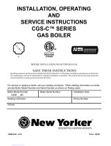
FIG. 1 Front and Rear View
Rear View
Front View

Hydronic Heating Boilers and
Domestic Water Heaters
6
INSTALLATION
This unit meets the safe lighting performance criteria with the
gas manifold and control assembly provided, as specified in
the ANSI standards for gas-fired units, ANSI Z21.13/CSA 4.9
and ANSI Z21.10.3/CSA 4.3.
LOCATING UNIT
1. Maintain all clearances from combustible construction
when locating unit. See Clearances from Combustible
Construction, this page.
2. Locate the unit so that if water connections should leak,
water damage will not occur. When such locations cannot
be avoided, install a suitable drain pan that is well-drained
under the unit. The pan must not restrict combustion air
flow. The appliance manufacturer is not responsible for
water damage in connection with this unit, or any of its
components.
3. Install indoor units so that the ignition system components
are protected from any water while operating or during
service.
4. Appliances located in a residential garage and in adjacent
spaces that open to the garage and are not part of the living
space of a dwelling unit must be installed so that all
burners and burner ignition devices have a minimum
clearance of not less than 18" (46 cm) above the floor. The
appliance must be located or protected so that it is not
subject to physical damage by a moving vehicle.
5. DO NOT install this appliance in any location where
gasoline or flammable vapors are likely to be present.
6. You must install unit on a level, non-combustible floor.
7. Do not install unit directly on carpet or other combustible
material. A concrete-over-wood floor is not considered
non-combustible. Maintain required clearances from
combustible surfaces.
If installing unit in an area with a combustible floor, you
must use a special combustible floor base. See Base for
Combustible Floors, on page 7.
8. For outdoor models, you must install an optional vent cap.
Instructions for mounting the vent cap are included in the
venting section. Do not install outdoor models directly on
the ground. You must install the outdoor unit on a concrete,
brick, block, or other non-combustible pad. Outdoor
models have additional special location and clearance
requirements. See Outdoor Installation Venting, page 26. A
wind proof cabinet protects the unit from weather.
Clearances from Combustible
Construction
Maintain minimum specified clearances for adequate
operation. Allow sufficient space for servicing pipe
connections, pump and other auxiliary equipment, as well as
the unit. See rating plate for specific service clearance
requirements.
Right Side 3" (7.5 cm)
Rear 3" (7.5 cm) (3" min.
from any surface)
Left Side 6" (15cm) (24" (0.61m)
suggested for service)
Front Alcove* (30" (0.76m)
suggested for service)
Top 3" (7.5cm)
Flue 1" (25.4mm)
Hot Water Pipes 1" (25.4mm)
*An Alcove is a closet without a door.
Note: No additional clearance is needed on the right side of the
unit for the observation port. An observation port is located on
both the right and left side of the unit.
No additional clearances for combustibles are needed
for use of the Direct Vent (DV) air inlet assembly.
FIG. 2 Clearances from Combustible Construction
3 INCH MINIMUM FROM UNIT TO WALL

Installation and
Service Manual
7
Base for Combustible Floors
There are no manufactured combustible floor base kits
available for 990,000 - 2,070,000 Btu models. See Table-A
below for floor base kits that are available.
You must construct a base for combustible floor installation.
Install unit over a base of hollow clay tiles or concrete blocks
from 8" to 12" thick and extending at least 24" beyond the unit
sides. Place tiles or blocks so that the holes line up horizontally
to provide a clear passage through the tiles or blocks. Place a
1/2" fireproof millboard over the top of the tile or block base.
Place a 20-gauge sheet metal cover over the fireproof
millboard. Center the unit on the base. Also follow this
procedure if electrical conduit runs through the floor beneath
the unit. This base must meet all local fire and safety codes.
FREEZE PROTECTION
Although these units are CSA International design certified for
outdoor installations, such installations are not recommended
in areas where the danger of freezing exists. You must provide
proper freeze protection for outdoor installations, units
installed in unheated mechanical rooms or where temperatures
may drop to the freezing point or lower. If freeze protection is
not provided for the system, a low ambient temperature alarm
is recommended for the mechanical room. Damage to the unit
by freezing is non-warrantable.
Anytime the temperature measured at any of the sensors
(except the outside air temperature sensor) drops below 35°F
(2°C), the control turns on the pump contact and the alarm
relay. The screen displays an error message (EO2).
Pump Operation
This unit is equipped with a pump delay feature as standard.
The delay is selectable through the temperature controller. As
shipped from the factory, the ΔT
MIN is set to “OFF”, which
creates a 30 second pump delay at the end of a Call for Heat.
The value of ΔT
MIN can be changed to a value between 1°F
and 20°F. This will cause the unit to continue pump operation
until the ΔT is less than the value selected (30 second
minimum).
A value of “ON” is selectable through the control for ΔT
MIN.
This will operate the pump continuously. Alternatively, the
pump can be powered by a separate circuit for continuous
operation.
Note: Pump relay is rated for 1 HP maximum.
Location
Locate indoor boilers and hot water supply boilers in a room
having a temperature safely above freezing [32°F (0°C)].
Hydronic System Antifreeze
Freeze protection for a heating boiler or hot water supply
boiler using an indirect coil can be provided by using hydronic
system antifreeze. Follow the appliance manufacturers
instructions. Do not use undiluted or automotive type
antifreeze.
Outdoor Boiler Installation
Adequate hydronic system antifreeze must be used. A snow
screen should be installed to prevent snow and ice
accumulation around the unit or its venting system.
WARNING: Do not use antifreeze in
domestic water heater applications.
CAUTION: A mechanical room
operating under a negative pressure may
experience a down draft in the flue of a
boiler which is not firing. The cold outside
air pulled down the flue may freeze a heat
exchanger. This condition must be
corrected to provide adequate freeze
protection.
399,999 CFK3301
500,000 CFK3302
650,000 CFK3303
750,000 CFK3304
TABLE - A
COMBUSTIBLE FLOOR KITS
Input Btu/hr Kit Number

Hydronic Heating Boilers and
Domestic Water Heaters
8
INSTALLATION
Continued
Shut-Down and Draining
If for any reason, the unit is to be shut off, the following
precautionary measures must be taken:
1. Shut off gas supply.
2. Shut off water supply.
3. Shut off electrical supply.
4. Drain the unit completely. Remove one threaded plug or
bulbwell from the inlet side of the front header and one
from the outlet side of the front header on the heat
exchanger. Blow all water out of the heat exchanger (see
FIG. 3).
5. Drain pump and piping.
FIG. 3 Draining Unit
Freeze Protection for a Heating
Boiler System (if required)
1. Use only properly diluted inhibited glycol antifreeze
designed for hydronic systems. Inhibited propylene glycol
is recommended for systems where incidental contact with
drinking water is possible.
2. A solution of 50% antifreeze will provide maximum
protection of approximately -30°F (-34°C).
3. Follow the instructions from the antifreeze manufacturer.
Quantity of antifreeze required based on total system
volume including expansion tank volume.
4. Glycol is denser than water and changes the viscosity of
the system. The addition of glycol will decrease heat
transfer and increase frictional loss in the boiler and related
piping. A larger pump with more capacity (15% to 25%
more) may be required to maintain desired flow rates and
prevent a noise problem in a glycol system.
5. Local codes may require a back flow preventer or actual
disconnect from city water supply when antifreeze is
added to the system.
COMBUSTION AND VENTILATION
AIR
Provisions for combustion and ventilation air must be in
accordance with Section 5.3, Air for Combustion and
Ventilation, of the latest edition of the National Fuel Gas Code,
ANSI Z223.1, in Canada, the latest edition of CAN/CGA-
B149 Installation Code for Gas Burning Appliances and
Equipment, or applicable provisions of the local building
codes.
Provide properly-sized openings to the equipment room to
assure adequate combustion air and proper ventilation when
the unit is installed with conventional venting or sidewall
venting.
Combustion Air Filter
This unit has a standard air filter located at the combustion air
inlet. This filter helps ensure clean air is used for the
combustion process. Check this filter every month and replace
when it becomes dirty. The filter size on the 399,999 - 750,000
units is 12" x 12" x 1" (30.5cm x 30.5cm x 2.5cm) and 16" x
16" x 1 (40.6cm x 40.6cm x 2.5 cm) on the 990,000 -
2,070,000 units. You can find these commercially available
filters at any home center or HVAC supply store.
For convenience and flexibility, you can direct the combustion
air inlet from either the back or right side of the unit. To
arrange the combustion air inlet for side entry, follow the steps
below:
1. Remove the metal panel from the unit’s side wall (see
FIG. 4).
2. Remove screws from the air filter/bracket assembly.
3. Move the filter/bracket assembly from the rear of unit to
the side opening (see FIG. 5).
4. Attach filter/bracket assembly to the unit’s side using the
pre-drilled screw holes.
5. Attach the metal panel to the rear combustion air opening
to seal it off.
WARNING: Do not use undiluted or
automotive type antifreeze.
DRAIN PLUG
DRAIN PLUG

Installation and
Service Manual
9
FIG. 4 Metal Panel Covering Side Combustion Air Inlet
FIG. 5 Moving Air Filter/Bracket Assembly from Rear of
Unit to Side
Combustion Air Options
This unit has four combustion air options.
1. Outside Combustion Air, No Ducts
You can direct outside combustion air to this unit using either
one or two permanent openings.
One Opening
The opening must have a minimum free area of one square
inch per 3000 Btu input (7cm
2
per kW). You must locate this
opening within 12" (30cm) of the top of the enclosure.
FIG. 6 Outside Combustion Air - Single Opening
Two Openings
The combustion air opening must have a minimum free area of
one square inch per 4000 Btu/hr input (5.5cm
2
per kW). You
must locate this opening within 12" (30cm) of the bottom of
the enclosure.
The ventilation air opening must have a minimum free area of
one square inch per 4000 Btu/hr input (5.5cm
2
per kW). You
must locate this opening within 12" (30cm) of the top of the
enclosure.
CAUTION: Under no circumstances
should the mechanical room ever be under a
negative pressure. Particular care should be
taken where exhaust fans, attic fans, clothes
dryers, compressors, air handling units, etc.,
may take away air from the unit.

Hydronic Heating Boilers and
Domestic Water Heaters
10
INSTALLATION
Continued
FIG. 7 Outside Combustion Air - Two Openings
2. Outside Combustion Air, Using Ducts
You can direct outside combustion air to this unit using two air
ducts to deliver the air to the boiler room.
Each of the two openings must have a minimum free area of
one square inch per 2000 Btu input (11cm
2
per kW).
FIG. 8 Outside Combustion Air Through Ducts
3. Outside Combustion Air - Using Direct Venting
With this option, you can connect combustion air vent piping
directly to the unit. See the information under Direct Venting
starting on page 22 for specific information regarding this
option.
4. Combustion Air from Interior Space
You can direct combustion air to this unit using air from an
adjoining interior space. You must provide two openings from
the boiler room to the adjoining room.
Each of the two openings must have a net free area of one
square inch per 1000 Btu input (22cm
2
per kW), but not less
than 100 square inches (645cm
2
).
FIG. 9 Combustion Air from Interior Space
All dimensions are based on net free area in square inches.
Metal louvers or screens reduce the free area of a combustion
air opening a minimum of approximately 25%. Check with
louver manufacturers for exact net free area of louvers. Where
two openings are provided, one must be within 12" (30 cm) of
the ceiling and one must be within 12" (30 cm) of the floor of
the mechanical room. Each opening must have a minimum net
free area as specified in TABLE–C, page 14. Single openings
shall be installed within 12" (30 cm) of the ceiling.
The combustion air supply must be completely free of any
flammable vapors that may ignite or chemical fumes which
may be corrosive to the unit. Common corrosive chemical
fumes which must be avoided are fluorocarbons and other
halogenated compounds, most commonly present as
refrigerants or solvents, such as Freon, trichlorethylene,
perchlorethylene, chlorine, etc. These chemicals, when burned
form acids which quickly attack the heat exchanger finned
tubes, headers, flue collectors, and the vent system. The result
is improper combustion and a non-warrantable, premature unit
failure.

Installation and
Service Manual
11
Exhaust Fans
Any fan or equipment which exhausts air from the boiler room
may deplete the combustion air supply and/or cause a down
draft in the venting system. Spillage of flue products from the
venting system into an occupied living space can cause a very
hazardous condition that must be immediately corrected. If a
fan is used to supply combustion air to the boiler room, the
installer must make sure that it does not cause drafts which
could lead to nuisance operational problems with the boiler.
Vertical DirectAire™ and Horizontal DirectAire™ venting
systems have specific requirements for combustion air ducts
from the outside which are directly connected to the unit. See
the requirements for combustion air duct in the venting
section.
VENTING
General Information
You must supply adequate combustion and ventilation air to
this unit. You must provide minimum clearances for the vent
terminal from adjacent buildings, windows that open, and
building openings. Follow all requirements set forth in the
latest edition of the National Fuel Gas Code, ANSI Z223.1, in
Canada, the latest edition of CAN/CGA Standard B149
Installation Code for Gas Burning Appliances and Equipment
or applicable local building codes. Vent installations for
connection to gas vents or chimneys must be in accordance
with Part 7, “Venting of Equipment” of the above-mentioned
standards.
Venting Support
Support horizontal portions of the venting system to prevent
sagging. Provide an upward slope of at least 1/4 inch per foot
(21mm/m) on all horizontal runs from the unit to the vertical
flue run or to the vent terminal on sidewall venting
installations.
Do not use an existing chimney as a raceway if another
appliance or fireplace is vented through the chimney. The
weight of the venting system must not rest on the unit. Provide
adequate support of the venting system. Follow all local and
applicable codes. Secure and seal all vent connections. Follow
the installation instructions from the vent material
manufacturer.
Vertical Vent Termination Clearances
and Location
The vent terminal should be vertical and exhaust outside the
building at least 2 feet (0.61m) above the highest point of the
roof within a 10 foot (3.05m) radius of the termination.
The vertical termination must be a minimum of 3 feet (0.91m)
above the point of exit.
A vertical termination less than 10 feet (3.05m) from a parapet
wall must be a minimum of 2 feet (0.61m) higher than the
parapet wall.
You must locate the air inlet termination elbow at least 12"
(30cm) above the roof or above normal snow levels.
Keep the vent cap clear of snow, ice, leaves, and debris to
avoid blocking the flue.
FIG. 10 Vent Termination from Peaked Roof - 10’ or Less
From Ridge
10' OR LESS
RIDGE
CHIMNEY
3' MIN.
2' MIN.
IMPORTANT: Examine the venting system at
least once each year. Check all joints and
vent pipe connections for tightness. Also
check for corrosion or deterioration. If you
find any problems, correct them at once.
IMPORTANT: Vent terminations are not shown
in Figures 10, 11, 12, and 13. Make sure all
vertical vents are installed with vent
terminations recommended by the vent
manufacturer.

Hydronic Heating Boilers and
Domestic Water Heaters
12
INSTALLATION
Continued
FIG. 11 Vent Termination from Peaked Roof More Than 10’
From Ridge
FIG. 12 Vent Termination from Flat Roof 10’ or Less from
Parapet Wall
FIG. 13 Vent Termination from Flat Roof More Than 10’
from Parapet Wall
Sidewall Vent Termination Clearances and
Location
Locate the bottom of the vent terminal at least 12 inches (30cm)
above grade and above normal snow levels. Locate the bottom of
the vent terminal at least 7 feet (2.13m) above grade when
located adjacent to public walkways. Do not terminate directly
above a public walkway.
Do not terminate the venting system in a window well, stairwell,
alcove, courtyard, or other recessed area. Do not terminate the
venting system below grade.
Locate vent termination at least 3 feet (0.91m) from an inside
corner of an L-shaped structure.
Provide a minimum clearance of 4 feet (1.2m) horizontally from
electric meters, gas meters, regulators, and relief equipment.
Never locate vent cap above or below electric meters, gas meters,
regulators, and relief equipment unless a 4 foot (1.2m) horizontal
clearance is maintained.
Terminate the venting system at least 3 feet (0.9m) above any
forced air inlet within 10 feet (3.05m).
Terminate the venting system at least 4 feet (1.2m) below, 4 feet
(1.2m) beside, or 1 foot (30cm) above any door, window, or
gravity air inlet into any building.
Locate vent termination at least 8 feet (2.4m) horizontally from
any combustion air intake located above the sidewall termination
cap.
TAB
L
10' OR LESS
NOTE: NO HEIGHT
ABOVE PARAPET
REQUIRED WHEN
DISTANCE FROM
WALLS OR PARAPET
IS MORE THAN 10'.
CHIMNEY
3' MIN.
WALL OR
PARAPET
10' OR LESS
CHIMNEY
CHIMNEY
3' MIN.
2' MIN.
2' MIN.
WALL OR
PARAPET
10'
RIDGE
CHIMNEY
3' MIN.
2' MIN.
MORE THAN 10'
CAUTION: Units which are shut down or
will not operate may experience freezing due to
convective air flow in flue pipe, through the air
inlet, or from negative pressure in the
mechanical room. In cold climates, operate
pump continuously to help prevent freezing of
boiler water. Provide proper freeze protection.
See Freeze Protection, page 7.

Installation and
Service Manual
13
Input Flue Air Inlet
Btu/hr Size Size*
399,999 6" 6"
500,000 6" 6"
650,000 8" 8"
750,000 8" 8"
990,000 10" 10"
1,260,000 12" 12"
1,440,000 12" 12"
1,800,000 14" 12"
2,070,000 14" 12"
* Minimum diameter for air inlet pipe. Installer may increase diameter one pipe
size for ease of installation, if needed.
Combustion Air Inlet Piping
The sidewall or vertical rooftop DirectAire™ combustion air
supply system has specific vent material and installation
requirements. The air inlet pipe connects directly to the unit to
supply combustion air. In most installations, the combustion air
inlet pipe will be a dedicated system with one air inlet pipe per
unit. You can combine multiple air inlets if the guidelines in
Combined Air Inlet Points, page 15 are followed. The air inlet
pipe will be connected to a combustion air inlet cap as specified
in this section.
For normal installations, this system uses a single-wall pipe to
supply combustion air from outdoors directly to the unit.
In cold climates, use a Type-B double-wall vent pipe or an
insulated single-wall pipe for combustion air. This will help
prevent moisture in the cool incoming air from condensing and
leaking from the inlet pipe.
Length of Air Inlet Pipe
The installed length of air inlet pipe from the unit to the outside air
inlet cap must not exceed 50 equivalent feet (15.2m). Subtract
5 feet (1.5m) of equivalent length for each 90° elbow. Subtract
2.5 feet (0.7m) of equivalent length for each 45° elbow.
Do not exceed the limits for the combustion air inlet piping
lengths.
Sidewall Air Inlet
The sidewall air inlet cap is supplied in the Horizontal
DirectAire™ Vent Kit. Order the kit from the appliance
manufacturer. This sidewall cap supplies combustion air for a
single unit only. See TABLE–D, page 19, for kit numbers.
Locate the unit as close as possible to the sidewall where you will
install the combustion air supply system.
FIG. 14 Sidewall Combustion Air Inlet
TABLE - B
Flue and Air Inlet Pipe Sizes
WARNING: Locate and install the
combustion air inlet cap correctly. Failure to
do so can allow the discharge of flue products
to be drawn into the combustion process.
This can result in incomplete combustion and
potentially hazardous levels of carbon
monoxide in the flue products. This will cause
operational problems and the spillage of flue
products. Spillage of flue products can cause
personal injury or death due to carbon
monoxide poisoning.

Hydronic Heating Boilers and
Domestic Water Heaters
14
INSTALLATION
Continued
FIG. 15 Air Inlet Cap for Sidewall Termination
To prevent recirculation of flue products from an adjacent vent
cap into the combustion air inlet, follow all applicable
clearance requirements in the latest edition of the National
Fuel Gas Code and/or CAN/CGA-B149 Installation Code and
instructions in the Installation and Service Manual.
You must install the combustion air inlet cap at least one foot
(0.30m) above ground level and above normal snow levels.
The point of termination for the combustion air inlet cap must
be at least 3 feet (0.91m) below the point of flue gas
termination (powered vent cap) if it is located within 10 feet
(3.05m) of the flue outlet from the powered vent cap. Make
sure to properly install the air inlet cap assembly on the air
inlet pipe.
You must install the combustion air inlet cap and the powered
vent cap on the same wall and in the same pressure zone.
Do not install the combustion air inlet cap closer than 10 feet
(3.05m) from an inside corner of an L-shaped structure.
Vertical Rooftop Air Inlet
Use the vertical air inlet terminations available from the
appliance manufacturer, recommended and/or supplied by the
vent manufacturer, or use two 90° elbows as described on
page 24.
FIG. 16 Roof Top Combustion Air Inlet
Clearances
You must locate the air inlet termination elbow at least 12"
(30cm) above the roof or above normal snow levels.
12"
3'
TABLE–C
Minimum Recommended Combustion Air Supply To Boiler Room
Combustion Air Source
Boiler Input Outside Air*/2 Openings Outside Air*/1 Opening Inside Air/2 Openings
399,999 100 in
2
(745 cm
2
) 133 in
2
(858 cm
2
) 400 in
2
(2581 cm
2
)
500,000 125 in
2
(806 cm
2
) 167 in
2
(1077 cm
2
) 500 in
2
(3226 cm
2
)
650,000 163 in
2
(1052 cm
2
) 217 in
2
(1400 cm
2
) 650 in
2
(4194 cm
2
)
750,000 188 in
2
(1213 cm
2
) 250 in
2
(1613 cm
2
) 750 in
2
(4839 cm
2
)
990,000 248 in
2
(1,600cm
2
) 330 in
2
(2,129 cm
2
) 990 in
2
(6,388 cm
2
)
1,260,000 315 in
2
(2,032cm
2
) 420 in
2
(2,710 cm
2
) 1260 in
2
(8,130 cm
2
)
1,440,000 360 in
2
(2,323cm
2
) 480 in
2
(3,097 cm
2
) 1440 in
2
(9,291 cm
2
)
1,800,000 450 in
2
(2,903cm
2
) 600 in
2
(3,871 cm
2
) 1800 in
2
(11,614 cm
2
)
2,070,000 518 in
2
(3,342cm
2
) 690 in
2
(4,452 cm
2
) 2070 in
2
(13,356 cm
2
)
*Outside air openings shall directly communicate with the outdoors. When combustion air is drawn from the outside through a duct, the net free area of each of the two openings
must have twice (2 times) the free area required for Outside Air/2 Openings. The above requirements are for the boiler only, additional gas fired units in the boiler room will require
an increase in the net free area to supply adequate combustion air for all units. Combustion air requirements are based on the latest edition of the National Fuel Gas Code, ANSI
Z223.1, in Canada refer to CAN/CGA-B149 Installation Code. Check all local code requirements for combustion air.

Installation and
Service Manual
15
If the air inlet cap is within a 10-foot (3.05m) radius of the flue
outlet, the point of termination for the combustion air inlet cap
must be at least 3 feet (0.91m) below the point of flue gas
termination (vent cap).
Do not install the combustion air inlet cap closer than 10 feet
(3.05m) from an inside corner of an L-shaped structure.
Combined Air Inlet Points
The air inlet pipes from multiple boilers can be combined to a
single common connection if the common air inlet pipe has a
cross sectional area equal to or larger than the total area of all
air inlet pipes connected to the common air inlet pipe.
Example: Two 10" air inlet pipes (78.5 in
2
area each) have a
total area of 157 in
2
and will require a 15" (176.7 in
2
area)
common air inlet pipe.
The air inlet point for multiple boiler air inlets must be
provided with an exterior opening which has a free area equal
to or greater than the total area of all air inlet pipes connected
to the common air inlet. This exterior opening for combustion
air must connect directly to the outdoors. The total length of
the combined air inlet pipe must not exceed a maximum of 50
(15.2m) equivalent feet. Subtract 5 feet (1.5m) for each 90°
elbow in the air inlet pipe. You must deduct the restriction in
area provided by any screens, grills or louvers installed in the
common air inlet point. These are common on the sidewall air
inlet openings. Screens, grills or louvers installed in the
common air inlet can reduce the free area of the opening from
25% to 75% based on the materials used.
Vent System Options
This unit has six venting options.
1. Conventional Negative Draft Venting
This option uses a vertical rooftop flue termination.
Combustion air is supplied from the mechanical room. See
column 2 for detailed information.
2. Vertical DirectAire™ Venting
This option uses a vertical conventional vent for flue products.
Combustion air is supplied by a pipe from the sidewall or
rooftop. See page 17 for venting details.
3. Sidewall Venting
This option uses a powered vent assembly to exhaust the flue
products out a sidewall vent termination. Combustion air is
supplied from the mechanical room. See page 19 for venting
details.
4. Horizontal DirectAire™ Venting
This option uses a powered vent assembly to exhaust the flue
products out a sidewall. Combustion air is supplied by a pipe
from the sidewall. See page 21 for venting details.
5. Direct Venting
This option uses a sealed AL29-4C flue and a separate
combustion air pipe to the outdoors. This system terminates
both the flue and combustion air inlet in the same pressure
zone. The flue outlet and combustion air intake may terminate
at either a sidewall (horizontal) or the rooftop (vertical). See
page 22 for venting details.
6. Outdoor Installation Venting
This option uses the installation of a special air inlet/vent cap
on top of the unit. See page 26 for venting details.
All units are shipped from the factory equipped for
conventional negative draft venting. All other optional vent
systems require the installation of specific vent kits and
venting materials. The following is a detailed explanation of
the installation requirements for each venting system,
components used and part numbers of vent kits for each model.
Barometric Damper Location
Any venting system option that requires a barometric damper
must adhere to the following directions for optimum
performance.
The preferred location for the barometric damper is in a tee or
collar installed in the vertical pipe rising from the unit’s flue
outlet. The barometric damper MUST NOT be installed in a bull
head tee installed on the unit’s flue outlet. The tee or collar
containing the barometric damper should be approximately three
feet vertically above the connection to the unit’s flue outlet. This
location ensures that any positive velocity pressure from the
unit’s internal combustion fan is dissipated and the flue products
are rising due to buoyancy generated from the temperature of the
flue products. Adjust the weights on the damper to ensure that
draft is maintained within the specified range.

Hydronic Heating Boilers and
Domestic Water Heaters
16
INSTALLATION
Continued
1. Conventional Negative Draft
Venting
FIG. 17 Conventional Negative Draft Vertical Venting with
Combustion Air Louvers
This option uses Type-B double-wall flue outlet piping. The
blower brings in combustion air. The buoyancy of the heated flue
products cause them to rise up through the flue pipe. The flue
outlet terminates at the rooftop.
Negative Draft
The negative draft in a conventional vent installation must be
within the range of 0.02 to 0.08 inches w.c. to ensure proper
operation. Make all draft readings while the unit is in stable
operation (approximately 2 to 5 minutes).
Connect the flue vent directly to the flue outlet opening on the top
of the unit. No additional draft diverter or barometric damper is
needed on single unit installations with a dedicated stack and a
negative draft within the specified range of 0.02 to 0.08 inches
w.c. If the draft in a dedicated stack for a single unit installation
exceeds the maximum specified draft, you must install a
barometric damper to control draft. Multiple unit installations
with combined venting or common venting with other Category I
negative draft appliances require each boiler to have a barometric
damper installed to regulate draft within the proper range.
Do not connect vent connectors serving appliances vented by
natural draft (negative draft) to any portion of a mechanical draft
system operating under positive pressure. Connecting to a positive
pressure stack may cause flue products to be discharged into the
living space causing serious health injury.
Flue Outlet Piping
With this venting option, you must use Type-B double-wall (or
equivalent) vent materials. Vent materials must be listed by a
nationally-recognized test agency for use as vent materials. Make
the connections from the unit vent to the outside stack as direct as
possible with no reduction in diameter. Use the National Fuel Gas
Code venting tables for double-wall vent to properly size all vent
connectors and stacks. Follow the vent manufacturer’s
instructions when installing Type-B vents and accessories, such as
firestop spacers, vent connectors, thimbles, caps, etc.
Provide adequate clearance to combustibles for the vent connector
and firestop.
When planning the venting system, avoid possible contact with
plumbing or electrical wiring inside walls, ceilings, and floors.
Locate the unit as close as possible to a chimney or gas vent.
Avoid long horizontal runs of the vent pipe, 90° elbows,
reductions and restrictions.
No additional draft diverter or barometric damper is required on
single unit installations with a dedicated stack and a negative draft
maintained between 0.02 to 0.08 inches w.c.
Common Venting Systems
You can combine the flue with the vent from any other negative
draft, Category I appliance. Using common venting for multiple
negative draft appliances requires you to install a barometric
damper with each unit. This will regulate draft within the proper
range. You must size the common vent and connectors from
multiple units per the venting tables for Type-B double-wall vents
in the latest edition of the National Fuel Gas Code, ANSI Z223.1
and/or CAN/CGA-B149 Installation Code.
Common venting systems may be too large when an existing unit
is removed.
At the time of removal of an existing appliance, the following
steps shall be followed with each appliance remaining connected
to the common venting system placed in operation, while other
appliances remaining connected to the common venting system
are not in operation.
1. Seal any unused opening in the common venting system.
2. Visually inspect the venting system for proper size and
horizontal pitch. Make sure there is no blockage or restriction,
leakage, corrosion and other unsafe conditions.
IMPORTANT: Before installing a venting
system, follow all venting clearances and
requirements found in the Venting, General
Information section, page 11.

Installation and
Service Manual
17
3. If possible, close all building doors and windows. Close all
doors between the space in which the appliances remaining
connected to the common venting system are located and
other building spaces.
4. Turn on clothes dryers and any other appliances not
connected to the common venting system. Turn on any
exhaust fans, such as range hoods and bathroom exhausts,
so they will operate at maximum speed. Do not operate a
summer exhaust fan.
5. Close fireplace dampers.
6. Place in operation the unit being inspected. Follow the
lighting instructions. Adjust thermostat so unit will operate
continuously.
7. Test for spillage at the draft hood/relief opening after
5 minutes of main burner operation. Use the flame of a
match or candle, or smoke from a cigarette, cigar or pipe.
8. After making sure that each appliance remaining
connected to the common venting system properly vents
when tested as above, return doors, windows, exhaust fans,
fireplace dampers and other gas burning appliances to their
previous conditions of use.
9. Correct any improper operation of the common venting
system so that the installation conforms to the latest edition
of the National Fuel Gas Code, ANSI Z223.1, in Canada,
the latest edition of CAN/CGA-B149 Installation Code for
Gas Burning Appliances and Equipment. When resizing
any portion of the common venting system, resize to
approach the minimum size as determined using the
appropriate tables of the latest edition of the National Fuel
Gas Code, ANSI Z223.1, in Canada, the latest edition of
CAN/CGA-B149 Installation Code for Gas Burning
Appliances and Equipment.
Masonry Chimney Installations
A masonry chimney must be properly sized for the installation
of a high efficiency gas-fired appliance. Venting of a high
efficiency appliance into a cold or oversized masonry chimney
can result in operational and safety problems. Exterior
masonry chimneys, with one or more sides exposed to cold
outdoor temperatures, are more likely to have venting
problems. The temperature of the flue products from a high
efficiency appliance may not be able to sufficiently heat the
masonry structure of the chimney to generate proper draft. This
will result in condensing of flue products, damage to the
masonry flue/tile, insufficient draft and possible spillage of
flue products into an occupied living space. Carefully inspect
all chimney systems before installation.
Inspection of a Masonry Chimney
A masonry chimney must be carefully inspected to determine its
suitability for the venting of flue products. A clay-tile-lined
chimney must be structurally sound, straight and free of
misaligned tile, gaps between liner sections, missing sections of
liner or any signs of condensate drainage at the breaching or clean
out. If there is any doubt about the condition of a masonry
chimney, it must be relined with a properly-sized and approved
chimney liner system. An unlined masonry chimney must not be
used to vent flue products from this high-efficiency unit. An
unlined chimney must be relined with an approved chimney
liner system when a new appliance is being attached to it.
Metallic liner systems (Type-B double-wall or flexible or rigid
metallic liners) are recommended. Consult with local code
officials to determine code requirements or the advisability of
using or relining a masonry chimney.
Vertical Vent Termination Clearances and Location
Follow all vertical venting termination information for
clearances and location under Vertical Vent Termination
Clearances and Location, page 11.
2. Vertical DirectAire™ Venting
The Vertical DirectAire™ vent system is the same as the
Conventional Negative Draft vent system, except it pulls
combustion air from the outdoors through a vertical air inlet.
Follow all requirements in 1. Conventional Negative Draft
Venting, page 16.
IMPORTANT: Before installing the venting
system, follow all venting clearances and and
requirements found in the Venting, General
Information section, page 11.
WARNING: Do not vent this unit into a
masonry chimney without a sealed stainless
steel liner system. Any breaks, leaks, or damage
to the masonry flue/tile will allow the positive-
pressure flue products to leak from the chimney
and into occupied living spaces. This could
cause serious injury or death due to carbon
monoxide poisoning and other harmful flue
products.
IMPORTANT: Check with local code officials to
determine code requirements or the advisability
of using a masonry chimney with a sealed
corrosion-resistant liner system.

Hydronic Heating Boilers and
Domestic Water Heaters
18
INSTALLATION
Continued
The Vertical DirectAire™ vent system requires you to install
two vent pipes directly to the unit; one vertical pipe with a
rooftop termination for the flue products and one pipe for
combustion air. For this venting option, you must purchase the
DV box adapter from the appliance manufacturer. The DV box
attaches to the air inlet of the unit. The pipe for combustion air
attaches to the DV box.
You can terminate the combustion air pipe either horizontally
with a sidewall air inlet or vertically with a rooftop air inlet.
The installed length of air inlet pipe from the unit to the outside air
inlet cap must not exceed 50 equivalent feet (15.2m).
FIG. 18 Vertical DirectAire Installation with Sidewall
Combustion Air Inlet
FIG. 19 Air Inlet Cap for Sidewall Termination
FIG. 20 Vertical DirectAire Installation with Roof Top
Combustion Air Inlet
Vent Kits
For single unit installations with sidewall air inlet, (see
FIG. 18) you must order the sidewall air inlet kit from the
appliance manufacturer. The part number for each SVK kit is
listed by unit size in TABLE–D.
For single unit installations with rooftop air inlet (see FIG. 20),
you must order the rooftop air inlet kit from the appliance
manufacturer. The part number for each VDK kit is listed by
unit size in TABLE-D. Purchase the flue pipe, rooftop flue
termination, and air inlet pipe locally.
There is no vent kit for combined air supply systems for
multiple units. Make sure the air inlet cap is properly sized.
You must purchase this cap locally.
Venting of Flue Products
For venting flue products vertically to the outdoors, follow all
requirements in the installation instructions for conventional
venting in this manual.
Follow all clearance requirements in Vertical Vent Termination
Clearances and Location, page 11.
A barometric damper is not required in the flue on Vertical
DirectAire™ installations if the draft is within the negative
0.02 to 0.08 inches w.c. required for proper operation. If the
draft exceeds this range, install a barometric damper.
™
WARNING: Only use a sidewall air inlet
cap supplied by the appliance
manufacturer or a rooftop air inlet cap
supplied by the vent manufacturer. Using
any other air inlet cap for single unit
installations or using a common air inlet
cap for multiple units with insufficient free
area and/or protections from wind and
weather may result in operational problems
and the spillage of flue products. Spillage
of flue products can cause personal injury
or death due to carbon monoxide
poisoning.
12"
3'

Installation and
Service Manual
19
*The SVK kits include a DV box adapter and sidewall air inlet cap. The VDK kits include
a DV box adapter and a rooftop air inlet cap.
3. Sidewall Venting
This option uses a powered vent assembly which pulls the flue
products out of the stack. This fan generates a negative draft at
the unit. Combustion air is drawn from the mechanical room
(see Combustion and Ventilation Air, page 8).
FIG. 21 Sidewall Venting Installation with an Induced
Draft Fan and Sidewall Vent Cap
Sidewall Fan
The sidewall fan can be mounted on the inside/outside
(depending upon model) with a sidewall vent hood installed on
the exterior wall. The sidewall fan and accessories are included
in a venting kit provided by the appliance manufacturer. See
TABLE–E for kit numbers.
The venting kit includes the sidewall fan, vent hood, tapered
vent adapter, barometric damper, proving switch and all
necessary relays to interlock with the heaters control system.
The tapered vent adapter reduces the vent size at the inlet to the
fan. There should be no reduction in vent diameter from the
unit’s flue outlet to the sidewall fan. The barometric damper
must be installed on the flue and adjusted to supply a negative
draft within the range of 0.04 to 0.08 inches w.c. while unit is
operating.
Flue Outlet Piping
With this venting option, you must use Type-B double-wall (or
equivalent) vent materials. Vent materials must be listed by a
nationally-recognized test agency for use as vent materials.
Make the connections from the unit vent to the sidewall
fan/cap as direct as possible with no reduction in diameter. Use
the National Fuel Gas Code venting tables for double-wall vent
to properly size all vent connectors and stacks. Follow the vent
manufacturer’s instructions when installing Type-B vents and
accessories, such as firestop spacers, vent connectors,
thimbles, caps, etc.
When planning the venting system, avoid possible contact with
plumbing or electrical wiring inside walls.
The maximum installed length of sidewall vent pipe with an
induced draft fan must not exceed 100 feet (30.5m). Subtract
5 feet (1.5m) for each 90° elbow. Subtract 2.5 feet (0.7m) for
each 45° elbow.
Sidewall Venting Termination
The sidewall vent cap must be installed on an exterior sidewall.
The sidewall fan/powered sidewall vent cap and accessories
are included in a venting kit which is furnished by the
appliance manufacturer in accordance with CSA International
requirements. This venting kit includes the powered sidewall
fan/cap, proving switch and all necessary relays to interlock
with the heaters control system.
The sidewall fan/powered vent cap must be interlocked with
the units control system to start the fan on a call for heat and
prove fan operation before the boiler fires. Plug-in and
terminal strip connections are provided on the unit for easy
connection of the factory supplied vent kit and control package
for the sidewall vent fan. See the installation instructions
provided with the vent kit.
Sidewall Venting Without Fan
For 399,999 - 750,000 Btu/hr models approved for sidewall
venting without an external power vent fan, you must install
specific vent kits and venting materials.
IMPORTANT: Before installing venting
system, follow all venting clearances and
requirements found in the Venting, General
Information section, page 11.
Input Horizontal Vertical
Btu/hr Kit* Kit*
399,999 SVK3047 VDK3026
500,000 SVK3047 VDK3026
650,000 SVK3048 VDK3027
750,000 SVK3048 VDK3027
990,000 SVK3040 VDK3023
1,260,000 SVK3041 VDK3024
1,440,000 SVK3041 VDK3024
1,800,000 SVK3041 VDK3024
2,070,000 SVK3041 VDK3024
TABLE-D
DirectAire™ Kits

Hydronic Heating Boilers and
Domestic Water Heaters
20
INSTALLATION
Continued
The following is a detailed explanation of Sidewall Venting
Without an External Power Vent Fan installation requirements.
Flue Outlet Piping
Venting Guidelines
If using this venting option, a sealed AL29-4C venting system
for flue products is required on all models of this appliance.
This venting system operates with a positive pressure in the
vent. The internal combustion air blowers generate this
positive pressure which operates the combustion process and
also exhausts the flue products from the building.
This vent system has specific vent material and installation
requirements. Only use listed sealed AL29-4C vent system
materials. Follow all installation requirements. See TABLE–B,
page 13 for proper pipe size for your unit. A list of sealed
AL29-4C flue pipe manufacturers is located on page 24.
Seal all vent joints and seams gas-tight.
Drain Tee Installation
A drain tee must be installed in the vent pipe to collect and
dispose of any condensate that may occur in the vent system.
The drain tee must be installed as the first fitting after the
horizontal ell on the top of the unit. Plastic drain tubing, sized
per the vent manufacturer’s instructions, shall be provided as a
drain line from the tee. The drain tubing must have a trap
provided by a 3" (7.6cm) diameter circular trap loop in the
drain tubing. Prime the trap loop by pouring a small quantity
of water into the drain hose before assembly to the vent. Secure
the trap loop in position with nylon wire ties. Use caution not
to collapse or restrict the condensate drain line with the nylon
wire ties. The condensate drain must be routed to a suitable
drain for disposal of condensate that may occur in the direct
vent system. Refer to the condensate drain installation
instructions as supplied by the manufacturer of the vent
material.
FIG. 22 Sidewall Vent
Connect the flue vent directly to the flue outlet opening on the
top of unit. Make the connections from the unit vent to the
outside stack as direct as possible with no reduction in
diameter. Provide adequate clearance to combustibles for the
vent connector and firestop. Follow the vent manufacturer’s
instructions when installing sealed AL29-4C vents and
accessories, such as firestop spacers, vent connectors,
thimbles, caps, etc.
Provide adequate clearance to combustibles for the vent
connector and firestop.
When planning the venting system, avoid possible contact with
plumbing or electrical wiring inside walls, ceilings, and floors.
Locate the unit as close as possible to chimney or gas vent.
When a vent system is disconnected for any reason, the flue
must be reassembled and resealed according to the vent
manufacturer’s instructions.
The installed length of flue from the unit to the outside point
of termination must not exceed 50 equivalent feet (15.2m).
Subtract 5 feet (1.5m) of equivalent length for each 90° elbow.
Subtract 2.5 feet (0.7m) of equivalent length for each 45°
elbow.
WARNING: Do not combine the flue
from this unit with the vent from any other
appliance. Do not combine flues from
multiple appliances into a common vent.
The flue from this unit must be a dedicated
stack.
/