Supermicro SUPERO X10DRW-i User manual
- Category
- Server/workstation motherboards
- Type
- User manual
This manual is also suitable for

USER’S MANUAL
Revision 1.0
X10DRW-i
X10DRW-iT

Manual Revision 1.0
Release Date: July 8, 2014
Unless you request and receive written permission from Super Micro Computer, Inc., you may not
copy any part of this document.
Information in this document is subject to change without notice. Other products and companies
referred to herein are trademarks or registered trademarks of their respective companies or mark
holders.
Copyright © 2014 by Super Micro Computer, Inc.
All rights reserved.
Printed in the United States of America
The information in this user’s manual has been carefully reviewed and is believed to be accurate.
The vendor assumes no responsibility for any inaccuracies that may be contained in this document,
and makes no commitment to update or to keep current the information in this manual, or to notify
any person or organization of the updates. Please Note: For the most up-to-date version of this
manual, please see our website at www.supermicro.com.
Super Micro Computer, Inc. ("Supermicro") reserves the right to make changes to the product
described in this manual at any time and without notice. This product, including software and docu-
mentation, is the property of Supermicro and/or its licensors, and is supplied only under a license.
Any use or reproduction of this product is not allowed, except as expressly permitted by the terms
of said license.
IN NO EVENT WILL SUPER MICRO COMPUTER, INC. BE LIABLE FOR DIRECT, INDIRECT,
SPECIAL, INCIDENTAL, SPECULATIVE OR CONSEQUENTIAL DAMAGES ARISING FROM THE
USE OR INABILITY TO USE THIS PRODUCT OR DOCUMENTATION, EVEN IF ADVISED OF
THE POSSIBILITY OF SUCH DAMAGES. IN PARTICULAR, SUPER MICRO COMPUTER, INC.
SHALL NOT HAVE LIABILITY FOR ANY HARDWARE, SOFTWARE, OR DATA STORED OR USED
WITH THE PRODUCT, INCLUDING THE COSTS OF REPAIRING, REPLACING, INTEGRATING,
INSTALLING OR RECOVERING SUCH HARDWARE, SOFTWARE, OR DATA.
Any disputes arising between the manufacturer and the customer shall be governed by the laws of
Santa Clara County in the State of California, USA. The State of California, County of Santa Clara
shall be the exclusive venue for the resolution of any such disputes. Supermicro's total liability for
all claims will not exceed the price paid for the hardware product.
FCC Statement: This equipment has been tested and found to comply with the limits for a Class
A digital device pursuant to Part 15 of the FCC Rules. These limits are designed to provide
reasonable protection against harmful interference when the equipment is operated in a commercial
environment. This equipment generates, uses, and can radiate radio frequency energy and, if not
installed and used in accordance with the manufacturer’s instruction manual, may cause harmful
interference with radio communications. Operation of this equipment in a residential area is likely
to cause harmful interference, in which case you will be required to correct the interference at your
own expense.
California Best Management Practices Regulations for Perchlorate Materials: This Perchlorate
warning applies only to products containing CR (Manganese Dioxide) Lithium coin cells. “Perchlorate
Material-special handling may apply. See www.dtsc.ca.gov/hazardouswaste/perchlorate”.
WARNING: Handling of lead solder materials used in this
product may expose you to lead, a chemical known to
the State of California to cause birth defects and other
reproductive harm.

Preface
This manual is written for system integrators, IT professionals, and
knowledgeable end-users. It provides information for the installation and use of the
X10DRW-i/X10DRW-iT motherboard.
About This Motherboard
The Super X10DRW-i(T) motherboard supports dual Intel E5-2600V3 processors
(Socket R3) that offer new Intel Microarchitecture 22nm Process Technology, de-
livering the best balanced solution of performance, power efciency, and features
to address the diverse needs of next-generation data centers. With the PCH C612
built in, the X10DRW-i(T) motherboard supports Integrated Clocking, Advanced
Management Bus Infrastructure, MCTP Protocol, and Intel® Node Manager 3.0. This
motherboard is optimized for high-performance WIO server platforms. Please refer
to our website (http://www.supermicro.com) for CPU and memory support updates.
Manual Organization
Chapter 1 describes the features, specications and performance of the moth-
erboard. It also provides detailed information about the Intel PCH C612 chipset.
Chapter 2 provides hardware installation instructions. Read this chapter when in-
stalling the processor, memory modules and other hardware components into the
system. If you encounter any problems, see Chapter 3, which describes trouble-
shooting procedures for video, memory, and system setup stored in the CMOS.
Chapter 4 includes an introduction to BIOS, and provides detailed information on
running the CMOS Setup utility.
Appendix A provides BIOS Error Beep Codes.
Appendix B lists Software Installation Instructions.
Appendix C contains UEFI BIOS Recovery instructions.
Preface
iii

iv
Conventions Used in the Manual
Pay special attention to the following symbols for proper system installation:
Warning: Important information given to ensure proper system installation or to prevent
damage to the components or injury to yourself;
Note: Additional information given to ensure proper system setup.
X10DRW-i/X10DRW-iT Motherboard User’s Manual

Preface
v
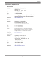
Contacting Supermicro
Headquarters
Address: Super Micro Computer, Inc.
980 Rock Ave.
San Jose, CA 95131 U.S.A.
Tel: +1 (408) 503-8000
Fax: +1 (408) 503-8008
Email: [email protected] (General Information)
[email protected] (Technical Support)
Web Site: www.supermicro.com
Europe
Address: Super Micro Computer B.V.
Het Sterrenbeeld 28, 5215 ML
's-Hertogenbosch, The Netherlands
Tel: +31 (0) 73-6400390
Fax: +31 (0) 73-6416525
Email: [email protected] (General Information)
[email protected] (Technical Support)
[email protected] (Customer Support)
Web Site: www.supermicro.nl
Asia-Pacic
Address: Super Micro Computer, Inc.
3F, No. 150, Jian 1st Rd.
Zhonghe Dist., New Taipei City 235
Taiwan (R.O.C)
Tel: +886-(2) 8226-3990
Fax: +886-(2) 8226-3992
Email: [email protected]
Web Site: www.supermicro.com.tw

vi
Table of Contents
Preface
Chapter 1 Overview
1-1 Overview ......................................................................................................... 1-1
1-2 Processor and Chipset Overview...................................................................1-11
1-3 Special Features ........................................................................................... 1-12
1-4 PC Health Monitoring .................................................................................... 1-12
Fan Status Monitor with Firmware Control .................................................. 1-12
Environmental Temperature Control ............................................................. 1-12
System Resource Alert ................................................................................. 1-12
1-5 ACPI Features ............................................................................................... 1-13
Slow Blinking LED for Suspend-State Indicator ........................................... 1-13
1-6 Power Supply ................................................................................................ 1-13
1-7 Advanced Power Management ..................................................................... 1-14
Intel
®
Intelligent Power Node Manager (NM) (Available when "Supermicro
Power Management (SPM)" is Installed) ...................................................... 1-14
Management Engine (ME) ............................................................................ 1-14
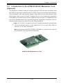
1-8 Introduction to the AOM-S3108-H8 Mezzanine Card (Optional) .................. 1-15
Chapter 2 Installation
2-1 Standardized Warning Statements ................................................................. 2-1
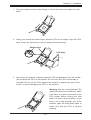
2-2 Static-Sensitive Devices .................................................................................. 2-4
2-3 Processor and Heatsink Installation................................................................ 2-5
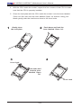
Installing the LGA2011 Processor ................................................................. 2-5
Installing a Passive CPU Heatsink ................................................................. 2-9
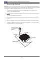
Removing the Heatsink ................................................................................. 2-10
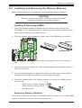
2-4 Installing and Removing the Memory Modules ..............................................2-11
Installing & Removing DIMMs ........................................................................2-11
Removing Memory Modules ..........................................................................2-11
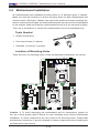
2-5 Motherboard Installation ................................................................................ 2-14
Tools Needed ................................................................................................ 2-14
Location of Mounting Holes .......................................................................... 2-14
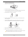
Installing the Motherboard ............................................................................ 2-15
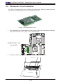
2-6 Mezzanine Card Installation .......................................................................... 2-16
2-7 Control Panel Connectors and I/O Ports ...................................................... 2-18
Back Panel Connectors and I/O Ports .......................................................... 2-18
Back Panel I/O Port Locations and Denitions ........................................... 2-18
Video Connection ..................................................................................... 2-19
Ethernet Ports .......................................................................................... 2-19
X10DRW-i/X10DRW-iT Motherboard User’s Manual

vii
Table of Contents
Universal Serial Bus (USB) ...................................................................... 2-20
Unit Identier Switch/UID LED Indicator .................................................. 2-21
Front Control Panel ....................................................................................... 2-22
Front Control Panel Pin Denitions............................................................... 2-23
NMI Button ............................................................................................... 2-23
Power LED .............................................................................................. 2-23
HDD/UID LED .......................................................................................... 2-24
NIC1/NIC2 LED Indicators ....................................................................... 2-24
Overheat (OH)/Fan Fail/PWR Fail/UID LED ............................................ 2-25
Power Fail LED ........................................................................................ 2-25
Reset Button ........................................................................................... 2-26
Power Button ........................................................................................... 2-26
2-8 Connecting Cables ........................................................................................ 2-27
Power Connectors ................................................................................... 2-27
Fan Headers ............................................................................................. 2-28
Chassis Intrusion ..................................................................................... 2-28
Internal Speaker ....................................................................................... 2-29
TPM/Port 80 Header ................................................................................ 2-29
Power SMB (I
2
C) Connector .................................................................... 2-30
IPMB ......................................................................................................... 2-30
S-SGPIO and I-SGPIO 1/2 Headers ........................................................ 2-31
Standby Power Header ............................................................................ 2-31
Serial Port ................................................................................................. 2-32
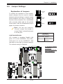
2-9 Jumper Settings ............................................................................................ 2-33
Explanation of Jumpers ................................................................................ 2-33
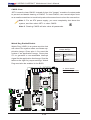
LAN Enable/Disable ................................................................................. 2-33
CMOS Clear ............................................................................................. 2-34
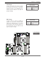
Watch Dog Enable/Disable ...................................................................... 2-34
VGA Enable .............................................................................................. 2-35
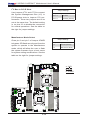
BMC Enable ............................................................................................ 2-35
I
2
C Bus to PCI-E Slots ............................................................................. 2-36
Manufacturer Mode Select ....................................................................... 2-36
2-10 Onboard LED Indicators ............................................................................... 2-37
LAN LEDs ................................................................................................. 2-37
IPMI_LAN LEDs ....................................................................................... 2-37
Onboard Power LED ............................................................................... 2-38
BMC Heartbeat LED ................................................................................ 2-38
2-11 SATA Connections ......................................................................................... 2-39

viii
SATA 3.0 Ports ......................................................................................... 2-39
Chapter 3 Troubleshooting
3-1 Troubleshooting Procedures ........................................................................... 3-1
3-2 Technical Support Procedures ........................................................................ 3-4
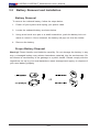
3-3 Battery Removal and Installation .................................................................... 3-6
3-4 Frequently Asked Questions ........................................................................... 3-7
3-5 Returning Merchandise for Service................................................................. 3-8
Chapter 4 BIOS
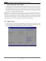
4-1 Introduction ...................................................................................................... 4-1
4-2 Main Setup ...................................................................................................... 4-2
4-3 Advanced Setup Congurations...................................................................... 4-4
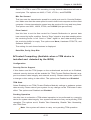
4-4 Event Logs ....................................................................................................4-33
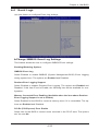
4-5 IPMI ............................................................................................................... 4-35
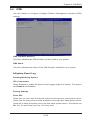
4-6 Security Settings ........................................................................................... 4-37
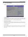
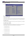
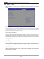
4-7 Boot Settings ................................................................................................. 4-38
4-8 Save & Exit ................................................................................................... 4-40
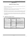
Appendix A BIOS Error Beep Codes
A-1 BIOS Error Beep Codes .................................................................................A-1
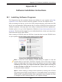
Appendix B Software Installation Instructions
B-1 Installing Software Programs ..........................................................................B-1
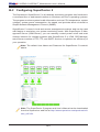
B-2 Conguring SuperDoctor 5 .............................................................................B-2
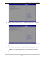
Appendix C UEFI BIOS Recovery Instructions
C-1 An Overview to the UEFI BIOS ......................................................................C-1
C-2 How to Recover the UEFI BIOS Image (-the Main BIOS Block)....................C-1
C-3 To Recover the Main BIOS Block Using a USB-Attached Device..................C-1
X10DRW-i/X10DRW-iT Motherboard User’s Manual

Chapter 1: Overview
1-1
Chapter 1
Overview
1-1 Overview
Checklist
Congratulations on purchasing your computer motherboard from an acknowledged
leader in the industry. Supermicro boards are designed with the utmost attention to
detail to provide you with the highest standards in quality and performance.
Please check that the following items have all been included with your motherboard.
If anything listed here is damaged or missing, contact your retailer.
The following items are included in the retail box.
• One (1) Supermicro Mainboard
• Six (6) Serial ATA cables (CBL-0044Lx6)
• One (1) Quick Reference Guide (MNL#1557-QRG)
Note 1: For your system to work properly, please follow the links below
to download all necessary drivers/utilities and the user's manual for your
motherboard.
•Supermicro product manuals: http://www.supermicro.com/support/manuals/
•Product Drivers and utilities: ftp://ftp.supermicro.com/
Note 2: For safety considerations, please refer to the complete list of safety
warnings posted on the Supermicro website at http:http://www.supermicro.
com/about/policies/safety_information.cfm.
If you have any questions, please contact our support team at support@
supermicro.com.

1-2
X10DRW-i/X10DRW-iT Motherboard User’s Manual
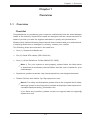
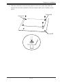
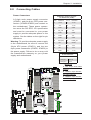
X10DRW-i(T) Motherboard Image
Note: All graphics shown in this manual were based upon the latest PCB
Revision available at the time of publishing of the manual. The motherboard
you've received may or may not look exactly the same as the graphics
shown in this manual.

Chapter 1: Overview
1-3
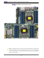
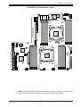
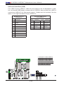
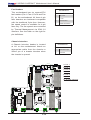
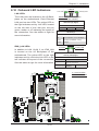
X10DRW-i(T) Motherboard Layout
Note: For the latest CPU/Memory updates, please refer to our website at
http://www.supermicro.com/products/motherboard/ for details.
S-SGPIO
I-SGPIO2
I-SGPIO1
JIPMB1
SAN MAC
IPMI CODE
JBAT1
JPWR1
S-SATA1
S-SATA0
S-SATA3
S-SATA2
I-SATA1
I-SATA0
I-SATA3
I-SATA2
I-SATA4
I-SATA5
BIOS
LICENSE
JPI2C1
JPWR2
JPWR3
JF1
JL1
JSTBY1
JTPM1
JVRM2
JVRM1
JPME2
JVR1
JWD1
JPG1
JPB1
JI2C1
JI2C2
JPL1
SP1
LED1
LEDM1
JBT1
FANB
FANA
FAN4
FAN3
FAN2
USB4/5(3.0)
AOM CPU1 PCI-E 3.0 X16
CPU1
CPU2
P2-DIMMG1
P2-DIMMH1
P2-DIMMG2
P2-DIMMH2
ALWAYS POPULATE DIMMx1 FIRST
ALWAYS POPULATE DIMMx1 FIRST
ALWAYS POPULATE DIMMx1 FIRST
P1-DIMMA1
P1-DIMMA2
P1-DIMMB1
P1-DIMMD2
P1-DIMMC1
P1-DIMMC2
P1-DIMMD1
P2-DIMMF2
P2-DIMMF1
P2-DIMME2
P2-DIMME1
SXB1C
SXB1B:CPU1 PCI-E 3.0 X16
+ CPU2 PCI-E 3.0 X16
UID-SW
LAN2
LAN1
USB2/3(3.0)
USB0/1(3.0)
IPMI_LAN
VGA
COM1
CLOSE 1st
OPEN 1st
CLOSE 1st
OPEN 1st
IPMI
Flash
BIOS
SXB2:CPU2PCI-E 3.0 X16
SXB1A
LAN
X10DRW-i(T)
Rev. 1.01
PCH
CTRL
LED2
BMC
P1-DIMMB2
FAN1
J35

1-4
X10DRW-i/X10DRW-iT Motherboard User’s Manual
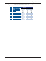
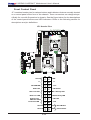
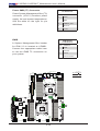
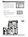
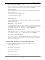
X10DRW-i(T) Quick Reference
Notes:
•See Chapter 2 for detailed information on jumpers, I/O ports and JF1 front
panel connections.
•" " indicates the location of "Pin 1".
•Jumpers/LED Indicators not indicated are for internal testing only.
•Use only the correct type of onboard CMOS battery as specied by the manufac-
turer. Do not install the onboard battery upside down to avoid possible explosion.
S-SGPIO
I-SGPIO2
I-SGPIO1
JIPMB1
SAN MAC
IPMI CODE
JBAT1
JPWR1
S-SATA1
S-SATA0
S-SATA3
S-SATA2
I-SATA1
I-SATA0
I-SATA3
I-SATA2
I-SATA4
I-SATA5
BIOS
LICENSE
JPI2C1
JPWR2
JPWR3
JF1
JL1
JSTBY1
JTPM1
JVRM2
JVRM1
JPME2
JVR1
JWD1
JPG1
JPB1
JI2C1
JI2C2
JPL1
SP1
LED1
LEDM1
JBT1
FANB
FANA
FAN4
FAN3
FAN2
USB4/5(3.0)
AOM CPU1 PCI-E 3.0 X16
CPU1
CPU2
P2-DIMMG1
P2-DIMMH1
P2-DIMMG2
P2-DIMMH2
ALWAYS POPULATE DIMMx1 FIRST
ALWAYS POPULATE DIMMx1 FIRST
ALWAYS POPULATE DIMMx1 FIRST
P1-DIMMA1
P1-DIMMA2
P1-DIMMB1
P1-DIMMD2
P1-DIMMC1
P1-DIMMC2
P1-DIMMD1
P2-DIMMF2
P2-DIMMF1
P2-DIMME2
P2-DIMME1
SXB1C
SXB1B:CPU1 PCI-E 3.0 X16
+ CPU2 PCI-E 3.0 X16
UID-SW
LAN2
LAN1
USB2/3(3.0)
USB0/1(3.0)
IPMI_LAN
VGA
COM1
CLOSE 1st
OPEN 1st
CLOSE 1st
OPEN 1st
IPMI
Flash
BIOS
SXB2:CPU2PCI-E 3.0 X16
SXB1A
LAN
X10DRW-i(T)
Rev. 1.01
PCH
CTRL
LED2
BMC
P1-DIMMB2
FAN1
J35

Chapter 1: Overview
1-5
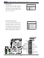
X10DRW-i(T) Jumpers
Jumper
Description Default Setting
JBT1
Clear CMOS See Chapter 3
JI
2
C1/JI
2
C2
SMB to PCI-E slots Pins 2-3 (Disabled)
JPB1 BMC Enable Pins 1-2 (Enabled)
JPG1 VGA Enable Pins 1-2 (Enabled)
JPL1 GLAN1/GLAN2 Enable (X10DRW-i)
10G_LAN1/10G_LAN2 Enable (X10DRW-iT)
Pins 1-2 (Enabled)
JPME2 Manufacture (ME) Mode Select Pins 1-2 (Normal)
JWD1 Watch-Dog Timer Enable Pins 1-2 (Reset)
X10DRW-i(T) Connectors
Connectors Description
AOM Slot (J35) PCI-E 3.0 x16 Add-On-Module (AOM) slot for the mezza-
nine HBA card (Note 1 on Page 1-6)
Battery (JBAT1) Onboard CMOS Battery (See Chpt. 3 for used battery dis-
posal)
COM1 Backplane COM port
Fan1-4, FanA/B CPU/System fan headers (Fan1-Fan4), PCH/Peripheral
fan headers (FanA-FanB)
JF1 Front_Panel_Control header
JIPMB1 4-pin external BMC I
2
C header (for IPMI-card support)
JL1 Chassis Intrusion
JPI
2
C1 Power supply SMBbus I
2
C header
JPWR1 24-pin ATX main power connector
JPWR2/3 12V 8-Pin power connectors
JSTBY1 Standby power connector
JTPM1 TPM (Trusted Platform Module)/Port 80 header
LAN1/LAN2 G-bit Ethernet (GLAN) ports 1/2 (for X10DRW-i)
10G-bit Ethernet (GLAN) ports 1/2 (for X10DRW-iT)
(IPMI)_LAN IPMI_Dedicated LAN support by the Aspeed controller
(I-)SATA 0-5 Intel SATA 3.0 connectors (0-5) from Intel PCH
(S)-SATA0-3 SATA 3.0 connectors (0-3) from Intel SCU
I-SGPIO1/2 Seria_Link General-Purpose I/O (SGPIO) headers for I-
SATA 3.0 connections (I-SGPIO1 for I-SATA0-3, I-SGPIO2
for I-SATA4/5)
S-SGPIO Seria_Link General-Purpose (SGPIO) I/O header for S-
SATA 3.0 connections 0-3
SP1 Internal speaker/buzzer
SXB1A SMC-proprietary SPEC slot (Left) (See Note 2 below.)

1-6
X10DRW-i/X10DRW-iT Motherboard User’s Manual
Warning!
To avoid damaging the power supply or the motherboard, please use a power supply
that contains a 24-pin and two 8-pin power connectors. Be sure to connect the power
supply to the 24-pin power connector (JPWR1), and two 8-pin power connectors
(JPWR2, JPWR3) on the motherboard. Failure in doing so may void the manufacturer
warranty on your power supply and motherboard.
SXB1B (CPU1/CPU2) PCI-E 3.0x16 + x16 add-on card slot (Left)
(Note 2 below.)
SXB1C SMC-proprietary SPEC slot (Left) (See Note 2 below.)
SXB2 SMC-proprietary PCI-E 3.0x16 add-on card slot (Right)
(See Note 3 below.)
UID-SW UID Switch
(BP) USB 0/1 (3.0) Backpanel USB 3.0 Port 0/ Port 1
(BP) USB 2/3 (3.0) Backpanel USB 3.0 connections 2/3
(FP) USB 4/5 (3.0) Front Accessible USB 3.0 connections header 4/5
VGA Backpanel VGA port
X10DRW-i(T) LED Indicators
LED Description State Status
LED1 Rear UID LED Blue: On Unit Identied
LED2 Onboard PWR LED On System Power On
LEDM1 BMC Heartbeat LED Green: Blinking BMC Normal
Note 1: For SAS support, be sure to use an SMC-proprietary mezzanine
card. Install the mezzanine card on the AOM PCIE 3.0 x16 slot (J35) for
SAS 3.0 support. Refer to Section 1-8 and Section 2-6 for more information.
Note 2: For SXB1A/SXB1B/SXB1C PCI-E slot to work properly, please use
an SMC-proprietary riser card (eg. RSC-R1UW-2E16) in the slot
Note 3: For SXB2 (CPU2 PCI-E 3.0X16) slot to work properly, please use
the SMC-proprietary riser card (PN: RSC-R2UW-2E8R).
Note 4: For the latest CPU/memory updates, please refer to our website
at http://www.supermicro.com/products/motherboard.

Chapter 1: Overview
1-7
Motherboard Features
CPU
• Dual Intel
®
E5-2600V3 Series Processors (Socket
R3-LGA 2011); each processor supports dual full-
width Intel QuickPath Interconnect (QPI) links (of up
to 9.6 GT/s one direction per QPI)
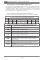
Memory
• Integrated memory controller supports:
Up to 1024 GB of 288-pin Registered (RDIMM)/Load
Reduced (LRDIMM) DDR4 ECC 2133/1866/1600 MHz
in 16 slots (2 DIMMs per channel).
Note 1: Memory speed support is dependent
upon the CPUs installed in the motherboard.
Note 2: For the latest CPU/memory updates,
please refer to our website at http://www.super-
micro.com/products/motherboard.
DIMM sizes
• DIMM Up to 64GB @ 1.2V
Chipset
• Intel® PCH C612
Expansion
• One (1) SMC-proprietary PCI-E 3.0 x16 slot (Right)
(SXB2) (See Note 3 on Page 1-6.)
• One (1) (CPU1+CPU2) SMC-proprietary PCI-E 3.0
x16 + x16 slot (Left) (SXB1B) (Note 2 on Page 1-6),
• One (1) PCI-E 3.0 x16 Add-On-Module (AOM) slot
for the mezzanine HBA card (J35) (See Note 1 on
Page 1-6.)
Slots
Graphics
• Graphics controller via the Aspeed AST2400 BMC
Network
• Intel i350 Gigabit (10/100/1000 Mb/s) Ethernet con-
troller for LAN 1/LAN 2 ports (X10DRW-i only),
• Intel X540 10_Gigabit Ethernet controller for LAN 1/
LAN 2 ports (X10DRW-iT only)
• Aspeed 2400 Base-board Controller (BMC) supports
IPMI_LAN 2.0
I/O Devices
SATA Connections
• SATA Ports Ten (10) SATA 3.0 ports (I-SATA
0-5, S-SATA0-3)
• RAID RAID 0, 1, 5, 10
IPMI 2.0
• IPMI 2.0 supported by Aspeed AST 2400

1-8
X10DRW-i/X10DRW-iT Motherboard User’s Manual
Serial (COM) Port
• One (1) Fast UART 16550 port
Peripheral
Devices
USB Devices
• Four (4) USB 3.0 ports on the rear I/O panel (USB
0/1, USB 2/3)
• Two (2) USB 3.0 ports for front access (USB 4/5)
BIOS
• 128Mb SPI AMI BIOS
®
SM Flash UEFI BIOS
• APM 1.2, APCI 2.3, ACPI 3.0/4.0, USB keyboard,
Plug & Play (PnP) and SMBIOS 2.3
Power
• ACPI/ACPM power management
Management
• Main switch override mechanism
• Power-on mode for AC power recovery
• Intel
®
Intelligent Power Node Manager 3.0 (Available
when "Supermicro Power Management (SPM)" is
installed and special power supply is used.)
• Management Engine (ME)
PC Health
PC Health/CPU Monitoring
Monitoring
• Onboard voltage monitoring for +3.3V, 3.3V standby,
+5V, +5V standby, CPU core, memory, chipset, and
battery voltages
• CPU/System overheat LED and control
• CPU Thermal Trip support
• Status Monitor for speed control
• Status Monitor for On/Off control
Fan Control
• Fan status monitoring via IPMI connections
• Dual Cooling Zone
• Low noise fan speed control
• Pulse Width Modulation (PWM) fan control
System
Management
• PECI (Platform Environment Conguration Interface)
2.0 support
• UID (Unit Identication)/Remote UID
• System resource alert via SuperDoctor 5
• SuperDoctor® 5, Watch Dog, NMI

Chapter 1: Overview
1-9
• Chassis Intrusion header and detection
Dimensions
• 13.05" (L) x 12.80" (W) (331.47 mm x 325.12 mm)
Note: For IPMI Conguration instructions, please refer to the Embedded
IPMI Conguration User's Guide available @ http://www.supermicro.com/
support/manuals/.

1-10
X10DRW-i/X10DRW-iT Motherboard User’s Manual
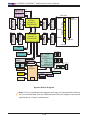
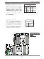
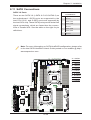
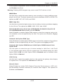
System Block Diagram
Note: This is a general block diagram and may not represent the features
on your motherboard. See the "Motherboard Features" pages for the actual
specications of each motherboard.
x16
P1
P1
P0
P0
CPU
FRONT
CPU
DMI
PE1
PE2
PE3
PE3
PE1PE2
DDR4 DIMM
4,5
port 0,1
REAR
DDR4 DIMM
#1
#2
DDR4 DIMM
A
G
x16
RIGHT
SLOT
SXB2
PCIE 3.0
x16
x16
RJ45
JLAN1
UL1
RJ45
JLAN2
PHY
RTL8211E
PET
[3,4,6,7]
DMI
PET5
LPC
USB2.0
[6]
QPI
Dual
LAN
I350BT2
PROCESSOR
PROCESSOR
QPI
DDR4 DIMM
#2
#1
DDR4 DIMM
DDR4 DIMM
BMC
SATA
Gen3
[0..5]
2,3
REAR
AST2400
DDR4 DIMM
B
DDR4 DIMM
C
D
SocketID 01
E
H
F
#1
#2
#1
#2
#1
2#
2
#
#1
#1
#2
#1
#2
x16
Left
SLOT
SXB1B
(lower)
PCIE
3.0
x16
SocketID 00
Left
SLOT
SXB1B
(Upper)
PCIE
3.0 x16
AOM
J35
PCIE
3.0
x16
PCH
SPI
SPI
FLASH
32MB
BMC
DDR3
VGA
IPMI
LAN
RJ45
TPM
Header
sSATA
Gen3
[0..3]
HDR
2x5
WIO Slots
SXB1A
SXB1B
SXB1C
SXB2
PCIE x16
Upper Lower
PCIE x16 PCIE x16
Left Slot
Right Slot
HWM
COM1
USB2.0
[0..5]
USB3.0
[1..6]
NC _SI(RMII)
x8
S-SATA3
SPI
FLASH
16MB
BIOS
DMI
S-SATA2
S-SATA1
S-SATA0
I-SATA0
I-SATA1
I-SATA2
I-SATA3
I-SATA4
I-SATA5
Rear

Chapter 1: Overview
1-11
1-2 Processor and Chipset Overview
Built upon the functionality and capability of the Intel E5-2600V3 Series processors
(Socket R3) and the Intel C612 PCH, the X10DRW-i(T) motherboard provides the
best balanced solution of performance, power efciency, and features for WIO
server platforms.
With support of new Intel Microarchitecture 22nm Processing Technology, the
X10DRW-i(T) dramatically increases performance for server applications
The PCH C612 chip provides Enterprise SMbus and MCTP support with the fol-
lowing features included:
•DDR4 288-pin memory support on Socket R3
•Integrated Clocking capable of extending to most 2S platforms
•Support for MCTP protocol and ME
•Support of SMBus speeds of up to 1 MHz for BMC connectivity
•GSX capable of GPIO expansion
•Improved I/O capabilities to high-storage-capacity congurations
•Flexible Management Infrastructure focused on Run-Time with support for
MCTP Protocol/End Points, and Management trafc over DMI
•SPI Enhancements
•Intel® Node Manager 3.0 for advanced power monitoring, capping and man-
agement for BMC enhancement
•BMC supports remote management, virtualization, and the security package
for enterprise platforms

1-12
X10DRW-i/X10DRW-iT Motherboard User’s Manual
1-3 Special Features
Recovery from AC Power Loss
The Basic I/O System (BIOS) provides a setting that determines how the system will
respond when AC power is lost and then restored to the system. You can choose for
the system to remain powered off (in which case you must press the power switch
to turn it back on), or for it to automatically return to the power-on state. See the
Advanced BIOS Setup section for this setting. The default setting is Last State.
1-4 PC Health Monitoring
This section describes the features of system health monitoring of the motherboard.
This motherboard has an onboard BaseBoard Management Controller (BMC) that
monitors system health. The onboard voltage monitor will scan the following on-
board voltages continuously: +3.3V, 3.3V standby, +5V, +5V standby, CPU core,
memory, chipset,and battery voltages. Once a voltage becomes unstable, a warning
is given, or an error message is sent to the screen. The user can adjust the voltage
thresholds to dene the sensitivity of the voltage monitor.
Fan Status Monitor with Firmware Control
System health monitoring support provided by the BMC controller can check the
RPM status of a cooling fan. The onboard CPU and chassis fan speeds are con-
trolled by IPMI Thermal Management.
Environmental Temperature Control
A thermal control sensor monitors the CPU temperature in real time and will turn
on the thermal control fan whenever the CPU temperature exceeds a user-dened
threshold. The overheat circuitry runs independently from the CPU. Once it detects
that the CPU temperature is too high, it will automatically turn on the thermal fan
control to prevent the CPU from overheating. The onboard chassis thermal circuitry
can monitor the overall system temperature and alert the user when the chassis
temperature is too high.
Note: To avoid possible system overheating, please be sure to provide
adequate airow to your system.
System Resource Alert
This feature is available when used with SuperDoctor 5 in the Windows OS or Linux
environment. SuperDoctor 5 is used to notify the user of certain system events.
Page is loading ...
Page is loading ...
Page is loading ...
Page is loading ...
Page is loading ...
Page is loading ...
Page is loading ...
Page is loading ...
Page is loading ...
Page is loading ...
Page is loading ...
Page is loading ...
Page is loading ...
Page is loading ...
Page is loading ...
Page is loading ...
Page is loading ...
Page is loading ...
Page is loading ...
Page is loading ...
Page is loading ...
Page is loading ...
Page is loading ...
Page is loading ...
Page is loading ...
Page is loading ...
Page is loading ...
Page is loading ...
Page is loading ...
Page is loading ...
Page is loading ...
Page is loading ...
Page is loading ...
Page is loading ...
Page is loading ...
Page is loading ...
Page is loading ...
Page is loading ...
Page is loading ...
Page is loading ...
Page is loading ...
Page is loading ...
Page is loading ...
Page is loading ...
Page is loading ...
Page is loading ...
Page is loading ...
Page is loading ...
Page is loading ...
Page is loading ...
Page is loading ...
Page is loading ...
Page is loading ...
Page is loading ...
Page is loading ...
Page is loading ...
Page is loading ...
Page is loading ...
Page is loading ...
Page is loading ...
Page is loading ...
Page is loading ...
Page is loading ...
Page is loading ...
Page is loading ...
Page is loading ...
Page is loading ...
Page is loading ...
Page is loading ...
Page is loading ...
Page is loading ...
Page is loading ...
Page is loading ...
Page is loading ...
Page is loading ...
Page is loading ...
Page is loading ...
Page is loading ...
Page is loading ...
Page is loading ...
Page is loading ...
Page is loading ...
Page is loading ...
Page is loading ...
Page is loading ...
Page is loading ...
Page is loading ...
Page is loading ...
Page is loading ...
Page is loading ...
Page is loading ...
Page is loading ...
Page is loading ...
Page is loading ...
Page is loading ...
Page is loading ...
Page is loading ...
Page is loading ...
Page is loading ...
Page is loading ...
Page is loading ...
Page is loading ...
Page is loading ...
-
 1
1
-
 2
2
-
 3
3
-
 4
4
-
 5
5
-
 6
6
-
 7
7
-
 8
8
-
 9
9
-
 10
10
-
 11
11
-
 12
12
-
 13
13
-
 14
14
-
 15
15
-
 16
16
-
 17
17
-
 18
18
-
 19
19
-
 20
20
-
 21
21
-
 22
22
-
 23
23
-
 24
24
-
 25
25
-
 26
26
-
 27
27
-
 28
28
-
 29
29
-
 30
30
-
 31
31
-
 32
32
-
 33
33
-
 34
34
-
 35
35
-
 36
36
-
 37
37
-
 38
38
-
 39
39
-
 40
40
-
 41
41
-
 42
42
-
 43
43
-
 44
44
-
 45
45
-
 46
46
-
 47
47
-
 48
48
-
 49
49
-
 50
50
-
 51
51
-
 52
52
-
 53
53
-
 54
54
-
 55
55
-
 56
56
-
 57
57
-
 58
58
-
 59
59
-
 60
60
-
 61
61
-
 62
62
-
 63
63
-
 64
64
-
 65
65
-
 66
66
-
 67
67
-
 68
68
-
 69
69
-
 70
70
-
 71
71
-
 72
72
-
 73
73
-
 74
74
-
 75
75
-
 76
76
-
 77
77
-
 78
78
-
 79
79
-
 80
80
-
 81
81
-
 82
82
-
 83
83
-
 84
84
-
 85
85
-
 86
86
-
 87
87
-
 88
88
-
 89
89
-
 90
90
-
 91
91
-
 92
92
-
 93
93
-
 94
94
-
 95
95
-
 96
96
-
 97
97
-
 98
98
-
 99
99
-
 100
100
-
 101
101
-
 102
102
-
 103
103
-
 104
104
-
 105
105
-
 106
106
-
 107
107
-
 108
108
-
 109
109
-
 110
110
-
 111
111
-
 112
112
-
 113
113
-
 114
114
-
 115
115
-
 116
116
-
 117
117
-
 118
118
-
 119
119
-
 120
120
-
 121
121
-
 122
122
-
 123
123


Supermicro SUPERO X10DRW-i User manual
- Category
- Server/workstation motherboards
- Type
- User manual
- This manual is also suitable for
Ask a question and I''ll find the answer in the document
Finding information in a document is now easier with AI
Related papers
-
Supermicro X10SRH-CF User manual
-
-
Supermicro A+ Series User manual
-
-
-
-
-
-
Supermicro SuperServer 6028R-WTRT User manual
-
Other documents
-
Midmark 6251, 6252, 6256 (Powered Carts - DC) Installation guide
-
Gigabyte GA-3CESL3-RH User manual
-
Vdwall SC-12 User manual
-
 IBASE Technology IB798 User manual
-
AMX MAX-AOM User manual
-
-
MSI 5520 Master Series User manual
-
Leadtek WinFast WS1030 User manual
-
ASRock Rack EP2C6212D16NM Quick Installation Manual
-
AIC HA201-TP User manual
