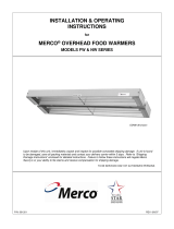
Merco EZFW-18 User manual

Category
Food warmers
Type
User manual
FWNWserviceman REV: 11/6/06
PARTS & SERVICE MANUAL for Overhead Food Warmers
Models FW & NW Series
THIS MANUAL SHOULD BE RETAINED FOR FUTURE USE.
IMPORTANT
INSTALLATION REQUIREMENTS
FW Series:
Do not install closer to ceiling than ¼ inch (0.25”). Do not install closer to a wall than 1-inch
(1.0”) at ends and 3 inches (3.0”) at sides. Minimum spacing between two or more units is 8
inches (8.0”) at sides. Do not install over combustible materials at a height of less than 12
inches (12.0”). For electrical supply connections use wire suitable for 90°C (200°F). Use
ceramic wire connectors (plastic wire connectors and/or plastic tape IS NOT to be used).
NW Series:
Do not install closer to a ceiling than 2 ¼ inches (2.25”). Do not install closer to a wall than 1-
inch (1.0”) at each end and 3 inches (3.0”) at sides. Minimum spacing between two or more
units is 8 inches (8.0”) at sides. Do not install over combustible material at a height of less than
12 inches (12.0”). For electrical supply connections use wire suitable for 90°C (20F). Use
ceramic wire connectors (plastic wire connectors and/or plastic tape IS NOT to be used).
FW & NW Series Service Manual
2
OVERHEAD FOOD WARMER MODEL IDENTIFICATION
1. Unit provided with high watt elements:
YES - Include prefix “HW
NO - NO “HW” prefix
2. Heating elements mounted in sockets:
YES - Include prefix “EZ”
NO - NO “EZ” prefix
3. Illumination lamps and sockets provided with elements:
YES - Include prefix “L”
NO - NO “L” prefix
4. Width of unit:
5” - Include prefix “NW-“
8” - Include prefix “FW-“
5. Unit length rounded to the nearest 6-inch increment equals the model suffix designation.
6. If all of the following exist, add suffix “X” to the model designation.
a. Units made after Jan. 1, 1992.
b. Overall length of unit, in inches (+/- 1/8”) equals the model designation (item 5 above).
c. The field-wiring junction is integrated into the end of the unit (units without the “X” designation use a separate
junction box for field wiring).
NOTE:
• Items 4 and 5 are provided on all Overhead Food Warmers.
• Items 1, 2 & 3 are all options that may or may not have been included with the equipment.
• Item 6 designates the newer style. All applicable prefix and suffix designations must be included to insure proper
identification of replacement parts.
• Item 6 section a: The serial number on Merco is also a date code, i.e.: 940512-12 would designate a manufacture
date of May 12, 1994 and the 12
th
unit of the day. The first two digits of “00” constitutes year 2000, first two digits
of “01” constitutes year 2001 and so on.
FW & NW Series Service Manual
3
DIMENSIONS:
(inches/cm)
Model # 120V
Voltage Amps
120 208V
120 240V Watts
Length
Inches / cm
Net Wt.
Lbs / kg
Ship Wt
Lbs / kg
Ship Size
Cu ft / cm
EZFW-18X 4.6 2.6 2.3 550 18/45.7 7/3.2 8/3.6 0.5/0.01
EZFW-24X 5.7 3.3 2.8 680 24/61 8/3.6 9/4.1 0.5/0.01
EZFW-30X 6.3 3.6 3.1 750 30/76.2 9/4.1 10/4.5 0.75/0.02
EZFW-36X 6.9 4.0 3.4 825 36/91.4 10/4.5 11/5 0.75/0.02
EZFW-48X 9.2 5.3 4.6 1100 48/121.9 11.5/5.2 13/5.9 1/0.03
EZFW-54X 11.9 6.9 6.0 1430 54/137.2 13.5/6.1 15/6.8 1/0.03
EZFW-60X 12.5 7.2 6.3 1500 60/152.4 15.5/7 17/7.7 1/0.03
EZFW-72X 13.8 7.9 6.9 1650 72/182.9 16.5/7.5 18/8.2 1/0.03
Model # 120V
Voltage Amps
120 208V
120 240V Watts
Length
Inches / cm
Net Wt.
Lbs / kg
Ship Wt
Lbs / kg
Ship Size
Cu ft / cm
FWM-18X 4.6 2.6 2.3 550 18/45.7 7/3.2 8/3.6 0.5/0.01
FWM-24X 5.7 3.3 2.8 680 24/61 8/3.6 9/4.1 0.5/0.01
FWM-30X 6.3 3.6 3.1 750 30/76.2 9/4.1 10/4.5 0.75/0.02
FWM-36X 6.9 4.0 3.4 825 36/91.4 10/4.5 11/5 0.75/0.02
FWM-48X 9.2 5.3 4.6 1100 48/121.9 11.5/5.2 13/5.9 1/0.03
FWM-54X 11.9 6.9 6.0 1430 54/137.2 13.5/6.1 15/6.8 1/0.03
FWM-60X 12.5 7.2 6.3 1500 60/152.4 15.5/7 17/7.7 1/0.03
FWM-72X 13.8 7.9 6.9 1650 72/182.9 16.5/7.5 18/8.2 1/0.03
See Table for Length 8 / 20.3
2.5 / 6.4
FW & NW Series Service Manual
4
FW & NW REPLACEMENT PARTS
FW & NW REPLACEMENT TUBE CHART
MODEL DESCRIPTION 120V 208V 240V MODEL DESCRIPTION 120V 208V 240V
FW-18 T-18, 550W 110004 110151 110217 EZFWM-18 EZTM-18, 550W 110666 N/A N/A
FW-24 T-24, 680W 110005 110152 110218 EZFWM-24 EZTM-24, 680W 110662 110790 110906
FW-30 T-30, 750W 110006 110153 110219 EZFWM-30 EZTM-30, 750W 110663 110791 110907
FW-36 T-36, 825W 110007 110154 110220 EZFWM-36 EZTM-36, 825W 110664 110792 110908
FW-42 T-42, 950W N/A N/A N/A EZFWM-42 EZTM-42, 950W N/A N/A N/A
FW-48 T-48, 1100W 110008 110155 110221 EZFWM-48 EZTM-48, 1100W 110665 110793 110909
FW-54 T-24, 680W 110005 110152 110218 EZFWM-54 EZTM-24, 680W 110662 110790 110906
T-30, 750W 110006 110153 110219 EZTM-30, 750W 110663 110791 110907
FW-60 T-30, 750W (2) 110006 110153 110219 EZFWM-60 EZTM-36, 825W-2 110663 110791 110907
FW-66 T-30, 750W 110006 110153 110219 EZFWM-66 EZTM-30, 750W 110663 110791 110907
T-36, 825W 110007 110154 110220 EZTM-36, 825W 110664 110792 110908
FW-72 T-36, 825W (2) 110007 110154 110220 EZFWM-72 EZTM-36, 825W-2 110664 110792 110908
FW-84 T-36, 825W 110007 110154 110220 EZFWM-84 EZTM-36, 825W 110664 110792 110908
T-48, 1100W 110008 110155 110221 EZTM-48, 1100W 110665 110793 110909
FW-96 T-48, 1100W (2) 110008 110155 110221 EZFWM-96 EZTM-48, 1100W-2 110665 110793 110909
EZFW-18 EZT-18, 550W 110649 110772 110892 EZFW-60 EZT-30, 750W (2) 110653 110776 110896
EZFW-24 EZT-24, 680W 110650 110773 110893 EZFW-66 EZT-30, 750W 110653 110776 110896
EZFW-30 EZT-30, 750W 110653 110776 110896 EZT-36, 825W 110655 110778 110898
EZFW-36 EZT-36, 825W 110655 110778 110898 EZFW-72 EZT-36, 825W (2) 110655 110778 110898
EZFW-42 EZT-42, 950W 110921 110922 110923 EZFW-84 EZT-36, 825W 110655 110778 110898
EZFW-48 EZT-48, 1100W 110657 110780 110900 EZT-48, 1100W 110657 110780 110900
EZFW-54 EZT-24, 680W 110650 110773 110893 EZFW-96 EZT-48, 1100W 110657 110780 110900
EZT-30, 750W 110653 110776 110896
HWEZFWM-24C
HWEZTM-24, 825W
110674 N/A 110910
Cordset, 120V (18 through 72) 050027
Cordset, 208 and 240V 000308
Cordset, 120/208V and 120/240V 072048
LFW or LNW units
Infinite Control, 120V w/term. 050377
Infinite Control, 208V & 240V 050378
Knob 000320
Socket, Tube w/suffix “X” 000672
Socket, w/o suffix “X” 050026
Pilot Light, w/clip 000274
On/Off Switch, 120V, 10A 000716
On/Off Switch, 120V 20A 000712
On/Off Switch, 208 & 240V 000711
On/Off Switch, 120V (Non “X) 000715
Socket, Appl. Lamp, Single 050461
Socket, Appl. Lamp, Twin 050463
Lamp, Appl. 120V* 000370
Lamp, Appl. 208V & 240V 000378
Wirenut, Ceramic (Hi-7) 000466
*includes 120/208V and 120/240V units
Notes: 120/208V models use 208V tubes, 120/240V models use 240V tubes.
Models with suffix “X” and/or prefix “L” use tubes identical to similarly identified models above.
For replacement tubes on models with prefix “HW” (except model HWEZFWM-24C) consult your Service Tube Chart.
To locate replacement elements for NW models, replace NW for FW in the chart above.
FW & NW Series Service Manual
5
EZFW & EZNW
ITEM # DESCRIPTION PART # ITEM # DESCRIPTION PART #
1 EZ-X End Closed Left
088194 EZFW
088196 EZNW
9 Reflector Call Factory
2 EZ-X End Closed Right
088193 EZFW
088195 EZNW
10 EZ-X Tandem End
088209 EZFW
088210 EZNW
3 Shell Call Factory
11 EZ Socket
000672 w/Suffix “X”
050025 w/o Suffix “X”
4 Switch
000716 Tog. 120V
000711 Tog. 204V
12 Tube Element See Tube Chart
5 Junction Box
See “Box, Junction”
in Price List
13 Appliance Bulb
000370 – 120V
000378 – 208/240V
6 Pilot Light 000274
14 Appliance Socket
050461 – Single
050463 – Twin
7 Infinite Control
050377 – 120V
050378 – 280/240V
15 Guard Wire
See Guard Assy. Kit
in Price List
8 Infinite Control Knob 000320
16 Cover Plate
088214 EZFW
088215 EZNW
Not
Shown
“Caution Hot” Sticker 000695
FW & NW Series Service Manual
6
FW & NW
ITEM # DESCRIPTION PART # ITEM # DESCRIPTION PART #
1 End Closed Left
088186 FW
088184 NW
9 Reflector Call Factory
2 End Closed Right
088187 FW
088152 NW
10 Tandem End
088209 FW
088210 NW
3 Shell Call Factory 11 Tube Element See Tube Chart
4 Switch
000716 Tog. 120V
000711 Tog. 204V
12 Appliance Bulb
000370 – 120V
000378 – 208/240V
5 Junction Box
See “Box, Junction”
in Price List
13 Appliance Socket
050461 – Single
050463 – Twin
6 Pilot Light 000274
14 Guard Wire
See Guard Assy. Kit
in Price List
7 Infinite Control
050377 – 120V
050378 – 280/240V
15 Cover Plate
088214 FW
088215 NW
8 Infinite Control Knob 000320
Not
Shown
“Caution Hot” Sticker 000695
FW & NW Series Service Manual
7
OVERHEAD FOOD WARMER PARTS
Unit P/N Unit P/N
Reflectors
FW-12 NLA NW-12 NLA
FW-18 050241 NW-18 050631
FW-24 050242 NW-24 NLA
FW-30 050243 NW-30 050639
FW-36 050244 NW-36 050643
FW-48 050245 NW-48 050647
FW-12X NLA NW-12X NLA
FW-18X 088342 NW-18X 088224
FW-24X 088343 NW-24X 088225
FW-30X 088344 NW-30X 088230
FW-36X 088345 NW-36X 088235
FW-42X 088350 NW-42X 088236
FW-48X 088346 NW-48X 088240
LFW-12 NLA LFW-12X NLA
LFW-18 050227 LFW-18X 088572
LFW-24 050228 LFW-24X 088573
LFW-36 050236 LFW-36X 088575
LFW-42 NLA LFW-42X 088576
LFW-48 050237 LFW-48X 088577
Wire Guard (Heat Tube)
FW-12X NLA NW-12X NLA
FW-18X 088482 NW-18X 088472
FW-24X 000864 NW-24X 000869
FW-30X 000866 NW-30X 000870
FW-36X 000867 NW-36X 000871
FW-42X 088486 NW-42X 088476
FW-48X 000868 NW-48X 000872
LFW-12 NLA LFW-12X NLA
LFW-18 NLA LFW-18X 088492
LFW-24 000832 LFW-24X 088493
LFW-30 000875 LFW-30X 088494
LFW-36 000876 LFW-36X 088495
LFW-42 NLA LFW-42X 088496
LFW-48 000877 LFW-48X 088497
FW & NW Series Service Manual
8
PORTABLE FOOD WARMERS
Cordsets Infinite Controls
120v 050017 120v 050377
208/240v 000308 208/240v 050378
120/208 – 120/240v 072048 Knob 000320
Tube Sockets Appl. Lamp Sockets (L models only)
w/suffix X 000672 Single 050461
w/o suffix X 050026 Twin 050463
Switches Misc
On/Off 120v 10a 000716 Pilot Light 000274
On/Off 120v 20a 000712 Wirenut 000466
On/Off 208/240v 000711 Lamp 120v 000370
On/Off 208/240v nonX 000715 Lamp 208/240v 000378
Heat Tubes (see chart)
FW & NW Series Service Manual
9
DIMENSIONS:
(inches/cm)
Model # 120V
Voltage Amps
120 208V
120 240V Watts
Length
Inches / cm
Net Wt.
Lbs / kg
Ship Wt
Lbs / kg
Ship Size
Cu ft / cm
EZNW-18X 4.6 2.6 2.3 550 18/45.7 5/2.3 6/2.7 0.5/0.01
EZNW-24X 5.7 3.3 2.8 680 24/61 6/2.27 7/3.2 0.5/0.01
EZNW-30X 6.3 3.6 3.1 750 30/76.2 7/3.2 8/3.6 0.5/0.01
EZNW-36X 6.9 4.0 3.4 825 36/91.4 8/3.6 9/4.1 0.75/0.02
EZNW-48X 9.2 5.3 4.6 1100 48/121.9 9.5/4.3 11/5 0.75/0.02
EZNW-60X 12.5 7.2 6.3 1500 60/152.4 12.5/5.7 14/6.4 0.75/0.02
EZNW-72X 13.8 7.9 6.9 1650 72/182.9 14.5/6.6 16/7.3 1/0.03
Model # 120V
Voltage Amps
120 208V
120 240V Watts
Length
Inches / cm
Net Wt.
Lbs / kg
Ship Wt
Lbs / kg
Ship Size
Cu ft / cm
FWM-18X 4.6 2.6 2.3 550 18/45.7 5/2.3 6/2.7 0.5/0.01
FWM-24X 5.7 3.3 2.8 680 24/61 6/2.27 7/3.2 0.5/0.01
FWM-30X 6.3 3.6 3.1 750 30/76.2 7/3.2 8/3.6 0.5/0.01
FWM-36X 6.9 4.0 3.4 825 36/91.4 8/3.6 9/4.1 0.75/0.02
FWM-48X 9.2 5.3 4.6 1100 48/121.9 9.5/4.3 11/5 0.75/0.02
FWM-60X 12.5 7.2 6.3 1500 60/152.4 12.5/5.7 14/6.4 0.75/0.02
FWM-72X 13.8 7.9 6.9 1650 72/182.9 14.5/6.6 16/7.3 1/0.03
See Table for Length 5 / 12.7
2.5 / 6.4
FW & NW Series Service Manual
10
EZ TUBE INSTALLATION AND REPLACEMENT INSTRUCTIONS
CAUTION: PRIOR TO REPLACING A HEAT TUBE, MAKE SURE THE CONTACT IS CLEAN.
IF IT IS BURNT OR DIRTY REPLACE THE SOCKET.
NOTE: These instructions are based on the unit laying on a work surface upside down.
CAUTION: Be sure the tube is centered in the socket terminals before placing the warmer in the
upright position and turning on power.
1. Remove the tube guard by pushing against the face of
the warmer with left thumb and “bowing” the cross brace
upward with your right hand. Pull the brace free.
Remove the lengthwise brace.
2. Place the left tip of the tube under the white
socket (receptacle of the terminal). Raise the tube
into the slot and apply enough inward pressure to
compress the terminal slightly.
3. While keeping the tube compressed into the left
terminal of the socket, position the right end of the tube
directly beneath the right socket.
4. Raise the tube into direct alignment with the
center of the right terminal. Release grip slowly
allowing the compressed left socket (terminal) to
lock tube into position.
FW & NW Series Service Manual
11
WIRE IN HEAT TUBE REPLACEMENT INSTRUCTIONS
1. Remove the 4 screws holding
the access panels onto the unit
(2 per panel).
2. Loosen the screws on the
heat tube collars (one on each
end of the tube).
5. Reassemble in reverse order.
* For units with an infinite control, both ends of the heat tube will have wire nuts.
4. Carefully remove the end
panel, remove the on/off switch
and disconnect the white wire.*
Remove the wire nut from the
opposite end of the heat tube.
The tube is now ready to be
taken out of the unit.
3. Remove the hex head-
retaining nut from the on/off
switch. Remove the 3 screws
holding the end panel onto the
unit (switch end).
FW & NW Series Service Manual
12
OVERHEAD & PORTABLE FOOD WARMER
INSTALLATION INSTRUCTIONS
MODELS
FW, LFW, NW, HWFW, HWLFW, FW-DUAL and LFW-DUAL series with or without prefix EZ
Merco Food Warmers are shipped completely assembled with wiring and ready for mounting. Use wire suitable for
90°C (200°F).
Each unit is shipped with two hanger tags mounted on each end. These should be used for chain mounting. Use #16
single-jack chain or equivalent. For undershelf or pass-through installation on 8” wide models, bend the hanger tag
90°.
CAUTIONon FW, EZFW, LFW, EZLFW, FW-DUAL, EZFW-DUAL, LFW-DUAL & EZLFW-DUAL series units, do
not install closer than ¼ inch from the top of the unit, 1 inch at ends, and 3 inches at the sides. Do not install over a
combustible surface closer than 12 inches for UL models and 15 inches for CSA models. On NW and EZNW series
warmers, do not install closer than 2 ¼ inches from the top of the unit, 1 inch at the ends, and 3 inches at the sides.
Do not install over a combustible surface closer than 18 inches. On HWFW, HWEZFW, HWLFW, and HWEZLFW
series warmers, do not install closer than 1 ½ inches from the top of the unit, 1 inch at end, and 3 inches at the
sides. Do not install over a combustible surface closer than 20 inches.
** Do not make any additional holes in the outside shell for BX or conduit. **
MODELS
PW240, FF240, EZPW and EZFF240
Merco Food Warmers are shipped completely assembled with wiring and ready for use. Place unit on a flat surface,
plug unit into the proper receptacle with the proper voltage.
CAUTION
Remove packing from around center and both ends of the heat tube when installing this unit.
Use porcelain wire connectors – DO NOT USE PLASTIC WIRE CONNECTORS.
Use high-temp glass cloth electrical tape when securing connectors.
**** DO NOT USE PLASTIC ELECTRICAL TAPE. ****
If your unit was supplied with appliance lamps, they are teflon coated. When replacing these bulbs they must be
replaced with similarly coated bulbs. This is mandatory to comply with NSF regulations. These bulbs may be
purchased from one of the Merco Savory authorized maintenance and repair centers.
FW & NW Series Service Manual
13
OVERHEAD & PORTABLE FOOD WARMER
OPERATION AND CLEANING INSTRUCTIONS
Your Merco Food Warmer has been designed to keep your cooked foods hot. For best product quality, product should
be placed on a flat surface approximately 18” below your Merco Food Warmer. (Please refer to the installation
instruction sheet for proper installation of your particular unit.) Product should be maintained at approximately 140°F.
Please be sure all packaging materials have been removed before operating unit.
TEMPERATURE ADJUSTMENT
Standard Merco Food Warmers
The standard unit comes only with an on/off toggle switch and does not have the capability of adjustable heat.
Units with optional Infinite Control
Due to the wide variation in applications, products and environments, the control dial(s) have setting numbers for your
convenience. For this reason you will need to experiment with the control dial(s) to determine which setting maintains
the best food qualities for your products. Due to a break-in period, the settings may need adjusting during the first 30
days.
To adjust the control dial(s), turn the dial(s) to setting #4 and monitor the temperature of your product. If the product
temperature is too low, adjust the dial(s) to a higher setting. If the temperature is too high, adjust the dial(s) to a lower
setting.
CLEANING
Turn unit off or disconnect the power supply and allow a few minutes for the unit to cool down before cleaning. Your
unit should be wiped down daily with a soft damp cloth and cleaned weekly with a scotch-brite pad. Avoid excessive
water or cleaning solution on the unit as it may allow the electrical connections to become corroded and/or cause the
unit to fail. Your unit may require more frequent cleaning depending on conditions in your particular environment. The
heat tube should be rotated one or two turns weekly to ensure a clean and proper connection which will help lengthen
the life of the heating element(s).
FW & NW Series Service Manual
14
TROUBLESHOOTING CHART
Problem Remedy
Unit doesn’t heat and *appliance lamps
don’t work.
* (when applicable)
A. Is unit plugged in and does
receptacle have power?
B. Are switches turned on?
C. Check cord and main power leads.
Unit temperature does not drop after
adjusting Infinite Control down.
Note: Not applicable on units with
toggle switch.
A. Infinite Control has failed and needs
to be replaced.
Appliance lamps don’t work but heating
elements do work*.
* (when applicable)
A. Replace appliance lamps.
B. Check wiring on 120/208v or
120/240v units.
Tubes don’t heat but appliance lamps
work.
A. Check for proper tube installation.
B. Visually check for break in tube
wire.
C. Check wiring for short or loose
connection.
D. Check Infinite Control for proper
operation.
FW & NW Series Service Manual
15
FW & NW Series Service Manual
16
FW & NW Series Service Manual
17
OVERHEAD FOOD WARMERS
EZFW-18X, 24X, 30X, 36X, 48X, 54X, 60X, 72X
EZNW-18X, 24X, 30X, 36X, 48X, 60X, 72X
OPTIONS AND ACCESSORIES
Ceiling mount bracket also available in Slimline series.
Infinitely Adjustable Heat Controls
– “Dial-in” the
perfect temperature for any food. Includes pilot light.
Dual Mounting (side
-
-
side)
Overhead warming in
any width. 4-inch spacing standard.
Tandem Mounting (end
-
to
-
end)
– Overhead warming
up to 12-feet in length.
Bright Incandescent Lighting
– Show off foods in
their best light.
Extra wide heat pattern
8”
13”
18”
FW & NW Series Service Manual
18
This page intentionally left blank.
FW & NW Series Service Manual
19
This page intentionally left blank.
FW & NW Series Service Manual
20
Merco Savory, LLC - Limited Warranty
Merco equipment is guaranteed to be free from quality problems in material and workmanship for a
period of ninety (90) days on labor and one (1) year on parts (excluding appliance lamps and heat
tubes) from installation or purchase date.
Savory equipment is guaranteed to be free from quality problems in material and workmanship for a
period of one (1) year parts and labor from date of purchase, or eighteen (18) months from date of
shipment from factory, whichever comes first.
Warranty beyond standard as follows:
Heat Tubes: One (1) year against burnout (not breakage) from date of purchase of equipment.
Hot Food Server: One (1) year labor, two (2) year parts.
Travel and Mileage
Savory equipment: Travel expenses limited to fifty (50) miles total.
Merco equipment: Labor warranty includes travel time not to exceed two (2) hours and/or mileage not to
exceed one hundred (100) miles. Portable equipment – equipment weighing less than ninety (90)
pounds must be delivered to the service agency at the owners expense.
Merco Savory, LLC obligation under this warranty shall be to repair or replace, at its option, any part or
unit which proves to be non-conforming due to quality problems in material or workmanship during the
warranty period. However, we make no warranty, express or implied, of cooking effect or of exact
capacity as subjective judgements and product variations may alter evaluation of equipment
performance. Warranty service must be provided by an authorized service agency. Shipping damage
is not covered by the manufacturer’s warranty.
This warranty is limited and supersedes all other warranties, express or implied. Merco Savory, LLC
neither assumes nor authorizes any person to assume for Merco Savory, LLC, any other obligation or
liability in connection with Merco or Savory equipment. Neither Merco Savory, LLC nor its employees or
agents shall be held liable for any claims for personal injuries or consequential damage or loss,
howsoever caused.
Merco Savory, LLC
1111 North Hadley Road
Fort Wayne, Indiana 46804
United States of America
Telephone: (260) 459-8200
Facsimile: (260) 436-0735
Service Hotline: (800) 678-9511
www.mercosavory.com
  • Page 1 1
  • Page 2 2
  • Page 3 3
  • Page 4 4
  • Page 5 5
  • Page 6 6
  • Page 7 7
  • Page 8 8
  • Page 9 9
  • Page 10 10
  • Page 11 11
  • Page 12 12
  • Page 13 13
  • Page 14 14
  • Page 15 15
  • Page 16 16
  • Page 17 17
  • Page 18 18
  • Page 19 19
  • Page 20 20

Merco EZFW-18 User manual

Category
Food warmers
Type
User manual

Ask a question and I''ll find the answer in the document

Finding information in a document is now easier with AI