Instruction Manual
5
Installation
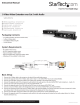
Turn off the VGA signal source device (computer).1.
Connect the local unit (ST124UTPEA/ST128UTPEA) HD-15 female 2.
INPUT connector to the signal source (computer) using an HD-15 male
to male cable.
Connect the 3. AUDIO IN connector of the local unit (ST124UTPEA/
ST128UTPEA) to the Audio Out port of the audio source (computer
sound card), using a 3.5mm audio cable.
Optional:4. Connect a compatible microphone cable to the MIC IN
connector on the local unit (ST124UTPEA/ST128UTPEA).
Connect a VGA monitor to the local unit (ST124UTPEA/ST128UTPEA) 5.
HD-15 female OUTPUT using an HD-15 male to male cable.
Connect the Local Unit (ST124UTPEA/ST128UTPEA) 6. CAT5 OUT port
to the Remote Unit (STUTPEALR(GB)) using CAT5 cable.
Optional: If you will be using the STUTPEA4X Line Splitter, connect
the Local Unit (ST124UTPEA/ST128UTPEA) CAT5 OUT port to the
Line Splitter using CAT5 cable. Once the Line Splitter has been
connected, you have the option of connecting to up to four remote units
(STUTPEALR(GB)) using CAT5 cable.
Once each of the Remote Units have been connected to either a Local 7.
Unit (ST124UTPEA/ST128UTPEA) or Line Splitter (STUTPEA4X),
connect a VGA monitor to the HD-15 OUTPUT connector provided by
the remote units as necessary.
Connect the Remote Unit 8. AUDIO OUT port to the device you will be
using to distribute audio (i.e. stereo receiver, amplifier etc.)
Connect the power cord on all units (Local, Line Splitter, Remote).9.
Turn on the monitor and PC and audio amplifier.10.
When situating the Local and Remote Units, please review the
maximum distance capability offered by each component (found
in the Specifications section


