APW Wyott FD Operating instructions

Category
Food warmers
Type
Operating instructions
Phone:
Fax: (214) 565-0976
Toll Free: (800) 527-2100
Website: www.apwwyott.com
(214) 421-7366
INSTALLATION
AND
OPERATING
INSTRUCTIONS
INTENDED FOR OTHER THAN HOUSEHOLD USE
Models: FD, FDD, FDL & FDDL
RETAIN THIS MANUAL FOR FUTURE REFERENCE
UNIT MUST BE KEPT CLEAR OF COMBUSTIBLES AT ALL TIMES
1
OVERHEAD WARMERS
APW WYOTT
729 Third Avenue
Dallas, TX 75226
This equipment has been engineered to provide you with year-round dependable service when used
according to the instructions in this manual and standard commercial kitchen practices.
Initial heating of unit may generate smoke or fumes and must be done in a well ventilated area.
Overexposure to smoke or fumes may cause nausea or dizziness.
FOR YOUR SAFETY: Do not store or use gasoline or other flammable vapors and
liquids in the vicinity of this or any other appliance.
!!
WARNING: Improper installation, adjustment, alteration, service or maintenance can
cause property damage, injury or death. Read the Installation, Operating and
Maintenance Instructions thoroughly before installing or servicing this equipment.
!!
ANSI/NSF4
R
SECTION
1
2
3
4
5
6
7
8
9
ITEM
Owners Information
Important Safety Information
Specifications
Operation
Cleaning
Troubleshooting
Wiring Diagrams
Parts Lists
Warranty
General Information
Installation Instructions
General Operation Instructions
Warranty Information
Electrical
Dimensions
Operating Instructions
General Cleaning Instructions
.
FD Wiring Diagrams
FDL Wiring Diagrams
FDD Wiring Diagrams
FDDL Wiring Diagrams
FD Replacement Parts
FDL Replacement Parts
FDD or FDDL Replacement Parts
PAGE
2
2
3
4
4
4
4
4
5
6
6
6
6
6
7
7
8
9
10
11
11
14
17
20
TABLE OF CONTENTS
2
1. OWNERS INFORMATION
General Information:
5. APW Wyott Overhead Foodwarmers are constructed from high quality stainless steel and available
in lengths from 18" to 96”. Utilizing a metal sheath-heating element with a specially designed reflector,
these units give uniform heat over the entire holding surface.
6. In Europe, contact anAPW Wyott authorized service agency for replacement light bulbs.
A. Always clean equipment thoroughly before first use (See cleaning instructions).
B. Provide the following clearances around foodwarmer:
1. Always clean equipment thoroughly before first use. (See general cleaning instructions).
2. Check rating label for your model designation and electrical rating.
3. For best results, use stainless steel countertops.
4. All dimensions in parenthesis in centimeters unless noted.
Installation Instructions:
3
C. Consult foodwarmer rating label for model designation and correct operating voltage and amperage.
D. Ceiling mounting brackets are provided with each foodwarmer for chain or shelf mounting. Remove
brackets form packaging and screws from ends of foodwarmer to attach brackets. Use four #10 screws
or studs with locknuts for shelf mounting. For chain mounting, use #14 jack chain and “S” hooks.
E. Remote switches are recommended. Longer switch life will result from cooler switch mounting
locations. Optional stainless steel remote toggle and infinite switch box kits are available. Installation
of remote switch box by service personnel requires 7/8" conduit, 1/4" push-on terminals, and no. 14
AWG copper wire suitable for at lest 90ºC. Mount remote box to flat surface with two #10 screws or
studs with locknuts. All wires marked as shown on wiring diagram.
F. Optional tubular stands are available for permanently mounting foodwarmers to non-combustible
countertops.
G. Optional portable legs are available for foodwarmers for use over non-combustible countertops.
H. Installation of cord sets by service personnel should utilize the strain relief, grounding stud, and
porcelain wire nuts provided with foodwarmers.
I. If unit is supplied with a power cord, the appliance must be positioned so that the plug is accessible.
NOTE: TO AVOID BURNING OR CHARRING OF MATERIALS IN THE SURFACE
BELOW THE FOODWARMER USE ONLY ABOVE AN ALL-METAL STRUCTURE
SUCHASATABLE OR COUNTERTOP. SEE MINIMUM CLEARANCE CHARTABOVE.
REMOTE SWITCHES ARE RECOMMENDED FOR UNDER SHELF MOUNTING.
LONGER SWITCH LIFE WILL RESULT FROM COOLER SWITCH MOUNTING
LOCATIONS.
!!
Do not install A = Minimum clearance (in inches) tocloser than:
B.
C
= Minimum clearance (in inches) to
FDD/FDDL-18
FDD/FDDL-24
FDD/FDDL-30
FDD/FDDL-36
FDD/FDDL-42
FDD/FDDL-48
FDD/FDDL-54
FDD/FDDL-60
FDD/FDDL-66
FDD/FDDL-72
FDD/FDDL-84
FDD/FDDL-96
FD/FDL-18
FD/FDL-24
FD/FDL-30
FD/FDL-36
FD/FDL-42
FD/FDL-48
FD/FDL-54
FD/FDL-60
FD/FDL-66
FD/FDL-72
FD/FDL-84
FD/FDL-96
28
28
28
28
28
28
28
28
28
28
N/A
N/A
16
16
16
16
16
16
16
16
16
16
N/A
N/A
12
12
12
12
12
12
12
12
12
12
N/A
N/A
2
2
2
2
2
2
2
2
2
2
N/A
N/A
2
2
2
2
2
2
2
2
2
2
N/A
N/A
2
2
2
2
2
2
2
2
2
2
N/A
N/A
24
24
24
24
24
24
24
24
24
24
24
24
16
16
16
16
16
16
16
16
16
16
16
16
12
12
12
12
12
12
12
12
12
12
12
12
2
2
2
2
2
2
2
2
2
2
2
2
2
2
2
2
2
2
2
2
2
2
2
2
2
2
2
2
2
2
2
2
2
2
2
2
MODEL A B C A B C
HIGH WATTAGE LOW WATTAGE
CLEARANCES FOR OVERHEADS
4
General Operation Instructions:
Warranty Information:
Reliability Backed By APW Wyott’s Warranty:
Service Information:
Electrical:
1. All foodservice equipment should be operated by trained personnel.
2. Do not allow your customers to come in contact with any surface labeled “CAUTION HOT”.
3. Never hold food below 150°F (66°C).
All APW Wyott Overhead Warmers are backed by a one year parts and labor warranty, including On-Site
Service calls within 50 miles of authorized service technicians.
Service Hotline (800) 733-2203
APW Wyott Overhead Warmers are designed, built and sold for commercial use and should be operated by
trained personnel only. Clearly post all CAUTIONS, WARNINGS and OPERATING INSTRUCTIONS near
each unit to insure proper operation and to reduce the chance of personal injury and/or equipment damage.
Always disconnect power before servicing the Overhead Warmer. Surfaces will remain hot after power has
been turned off. Allow unit to cool before cleaning or servicing. Never clean the Overhead Warmer by
immersing it in water. The Overhead Warmer is not protected against water jets; DO NOT CLEAN
OVERHEAD WARMER WITHAWATER JET. Always clean equipment before first use.
If the supply cord is damaged, an authorized service agent or a similarly qualified person must replace it to
avoid a hazard or voiding the warranty.
2. SAFETY INFORMATION
3. SPECIFICATIONS
A. Single-phase operation at 120, 208, 230, and 240 volts. (See label on each unit).
B. Field-wired units provided with 7/8" conduit hole, 6" long leads, and porcelain wire nuts. For supply
connections, use minimum no. 14 AWG copper wires suitable for at least 90ºC.
C. U.S. cord-connected units provided with following plug configuration:
1. 120 volt up to 1440 watts = NEMA 5-15P; 120 volt up to 1920 watts = NEMA 5-20P
2. 208 volt up to 2496 watts = NEMA 6-15P; 208 volt up to 3328 watts = NEMA 6-20P
3. 240 volt up to 2880 watts = NEMA 6-15P; 240 volt up to 3840 watts = NEMA 6-20P
D European cord-connected units provided with following plug configuration:
1. Continental Europe230 volt up to 3600 watts = Schuko CEE7/7
2. UK230 volt up to 2930 watts = Bs1363
5
Overall Dimensions:
.875 [ 2.22 ] CONDUIT HOLE
POWER LEADS
6.923
[ 17.58]
6.000
[ 15.24 ]
PILOT LIGHT
TOGGLE OR INFINITE SWITCH
RATING LABEL
OVERHEAD WARMER LENGTH
18.00 [45.72] TO 72.00 [182.88]
.75
[1.91]
3.58
[9.09]
MOUNTING BRACKETS
1.00
[2.55]
FD MODELS
9.125
[ 23.18]
10.048
[ 25.52 ]
FDL MODELS
15.125
[ 38.42 ]
16.971
[ 43.11]
FDD, FDDL MODELS
FOR INSTALLATION ABOVE NONCOMBUSTIBLE SURFACE
5/16 -18 STUD MOUNT
1.00[2.54] SQUARE
S/S TUBING
16.00
[
40.64
]
OVERHEAD WARMER LENGTH + 1.06[2.7]
18.50
[ 46.99
46.99
]
TUBULAR STAND KIT
FOR USE ABOVE NONCOMBUSTIBLE SURFACE
1.00[2.54] SQUARE
S/S TUBING
11.27 [28.63]
11.00 [27.94]
16.00
[
40.64
]
18.50
[
]
OVERHEAD WARMER LENGTH + 2.06[5.23]
PORTABLE LEG KIT
WARNING: ELECTRICAL SHOCK HAZARD. FAILURE TO FOLLOW THE
INSTRUCTIONS IN THIS MANUAL COULD RESULT IN SERIOUS INJURY OR
DEATH.
Electrical Ground is required on this appliance.
Do not modify the power supply cord plug. If it does not fit into the outlet, have
the proper outlet installed by a qualified electrician
Do not use an extension cord with this appliance.
Check with a qualified electrician if you are unsure as to whether the appliance
is properly grounded.
!
!
6
4. Operation
5. Cleaning
6. Troubleshooting
A. All foodservice equipment should be operated by trained personnel.
B. Do not allow your customers to come in contact with any surface labeled “CAUTION HOT”.
C. Switch on unit. Place precooked product under heat source. Maximum heat coverage equivalent to
unit length.
D. Never hold food below 150ºF.
A. Never clean any electrical unit by immersing it in water.
B. Never clean any electrical unit using water jets.
C. Disconnect power before cleaning or servicing units.
D. Clean unit daily. Use warm, soapy water. Mild cleansers and non-abrasive pads may be used to
remove baked-on food.
A. Always ask and check:
1. Is the unit connected to a live power source?
2. Check the circuit breaker.
3. Is the power switch on and pilot light illuminating?
4. Check the rating label. Is the unit operating on proper voltage?
B. If the above checks out, and problems still exist, call an APW Wyott authorized service agency.
C. All service should be performed by an APW Wyott authorized service agency.
General Cleaning Instructions:
Turn off before surface cleaning.
All service should be performed by an APW
authorized service agency.
7
BLUE
ELEMENT
GL1L
2
BROWN
LIGHT
PILOT
TOGGLE
SWITCH
GREEN
BROWN
200-240V: BLUE
120V: WHITE
GREEN
G
ELEMENT
200-240V: BLUE
BROWN
120V: WHITE
REMOTE CONFIGURATION
FD18-72 WIRING DIAGRAM
INFINITE CONTROL CONFIGURATION
TOGGLE SWITCH CONFIGURATION
L2
L2
INDICATOR LIGHT
L1
HEATING ELEMENT
L1
H1
DISPLAY LIGHT
PILOT
H2
EGO
INFINITE
CONTROL
7. WIRING DIAGRAMS
8
GREEN
WHITE
BLACK
36,42,48,54 MODELS
TWO LAMPHOLDERSONE LAMPHOLDER
18,24,30 MODELS
ELEMENT
1
2
3
4
5
200-240V: BLUE
BROWN
120V: WHITE
BROWN
6
7
WHITE
BLACK
BLUE
200-240V: BLUE
120V: WHITE
L1
N/L2
G
N/L2
L1
L
ABELS
WHITE
BLACK
THREE LAMPHOLDERS
60,66,72 MODELS
WHITE
BLACK
FOUR LAMPHOLDERS
84,96 MODELS
BLUE
6
7
BLUE
6
7
BROWN
BLUE
BROWN
200-240V: BLUE
BROWN
G
L1
N/L2
GREEN
WHITE
BLACK
WHITE
36,42,48,54 MODELS
TWO LAMPHOLDERSONE LAMPHOLDER
18,24,30 MODELS
ELEMENT
TOGGLE
SWITCH
LIGHT
PILOT
1
2 3
6
7
8
9
BLACK
5 4
120V: WHITE
BLUE
BLUE
L
ABELS
BLACK
60,66,72 MODELS
THREE LAMPHOLDERS
WHITE
BLUE
8
9
BLACK
84,96 MODELS
FOUR LAMPHOLDERS
WHITE
BLUE
8
9
REMOTE CONFIGURATION
FDL18-72 WIRING DIAGRAM
INFINITE CONTROL CONFIGURATION
TOGGLE SWITCH CONFIGURATION
L2
L2
INDICATOR LIGHT
L1
HEATING ELEMENT
L1
H1
DISPLAY LIGHT
PILOT
H2
EGO
INFINITE
CONTROL
9
REMOTE CONFIGURATION
FDD18-72 WIRING DIAGRAM
INFINITE CONTROL CONFIGURATION
TOGGLE SWITCH CONFIGURATION
GREEN
G
200-240V: BLUE
ELEMENT
BROWN
120V: WHITE
N/L2
L1
ELEMENT
200-240V: BLUE
120V: WHITE
BROWN
L1
N/L2
LABELS
LABELS
L2
L2
INDICATOR LIGHT
L1
HEATING ELEMENT
L1
H1
DISPLAY LIGHT
PILOT
H2
EGO
INFINITE
CONTROL
LABELS
10
REMOTE CONFIGURATION
FDDL18-72 WIRING DIAGRAM
INFINITE CONTROL CONFIGURATION
TOGGLE SWITCH CONFIGURATION
L2
L2
INDICATOR LIGHT
L1
HEATING ELEMENT
L1
H1
DISPLAY LIGHT
PILOT
H2
EGO
INFINITE
CONTROL
11
MODEL “FD” OVERHEAD WARMERS REPLACEMENT PARTS CATALOG
FD18
FD24
FD30
FD36
FD42
FD48
FD54
FD60
FD66
FD72
FD84
FD96
FD Followed by 18, 24, 30, 36, 42, 48, 54, 60, 66, 72, 84, or 96
120 400 250
208 400 250
230 368 294
240 400 320
120 575 350
208 575 350
230 529 322
240 575 350
120 760 450
208 760 450
230 698 414
240 760 450
120 920 575
208 920 575
230 845 529
240 920 575
120 1100 675
208 1100 675
230 1011 620
240 1100 675
120 1265 800
208 1265 800
230 1162 735
240 1265 800
120 1425 925
208 1425 925
230 1309 850
240 1425 925
120 1600 1050
208 1610 1050
230 1479 965
240 1610 1050
208 1800 1160
230 1654 1066
240 1800 1160
208 1980 1275
230 1819 1171
240 1980 1275
208 --- 2050
230 --- 1948
240 --- 2050
208 --- 2400
230 --- 2280
240 --- 2400
FOR COMPLETE STYLE AND OPTION DESIGNATION:
ADD ONE SUFFIX FROM EACH FOLLOWING CATEGORY AFTER THE MODEL AND LENGTH
H=HIGH WATTAGE 1=120V I=INFINITE CONTROL
L=LOW WATTAGE 2=208V T=TOGGLE SWITCH
3=240V R=REMOTE CONTROL/SWITCH
A WARMER, 48” LONG, HIGH WATTAGE, 208V, WITH INFINITE CONTROL = OH48H2I
WATTAGE VOLTAGE SWITCH
EXAMPLE:
MODEL VOLTS HIGH WATTAGE LOW WATTAGE
8. PARTS LISTS
12
FD18 THRU 96 OVERHEAD WARMERS
ITEM PART NUMBER DESCRIPTION ITEM PART NUMBER DESCRIPTION
13
FD-18 Thru FD-96 EXPLODED VIEW
10
9
8
7
6
18
15
14
11
17
1
2
12
3
16
4
5
13
2
3
14
MODEL “FDL” LIGHTED OVERHEAD WARMERS REPLACEMENT PARTS CATALOG
FDL Followed by 18, 24, 30, 36, 42, 48, 54, 60, 66, 72, 84, or 96
FOR COMPLETE STYLE AND OPTION DESIGNATION:
ADD ONE SUFFIX FROM EACH FOLLOWING CATEGORY AFTER THE MODEL AND LENGTH
H=HIGH WATTAGE 1=120V I=INFINITE CONTROL
L=LOW WATTAGE 2=208V T=TOGGLE SWITCH
3=240V R=REMOTE CONTROL/SWITCH
A LIGHTED WARMER, 48” LONG, HIGH WATTAGE, 208V, WITH INFINITE CONTROL = OHL48H2I
WATTAGE VOLTAGE SWITCH
EXAMPLE:
MODEL VOLTS HIGH WATTAGE LOW WATTAGE
FDL18 120 480 330
208 462 312
230 441 368
240 480 400
FDL24 120 655 430
208 637 412
230 602 395
240 655 430
FDL30 120 840 530
208 822 512
230 772 487
240 840 530
FDL36 120 1080 735
208 1044 699
230 992 676
240 1080 735
FDL42 120 1260 835
208 1224 799
230 1158 767
240 1260 835
FDL48 120 1425 960
208 1389 924
230 1309 882
240 1425 960
FDL54 120 1585 1085
208 1549 1049
230 1456 997
240 1585 1085
FDL60 120 1840 1290
208 1796 1236
230 1700 1185
240 1850 1290
FDL66 208 1986 1346
230 1874 1286
240 2040 1400
FDL72 208 2166 1461
230 2039 1392
240 2220 1515
FDL84 208 --- 2298
230 --- 2177
240 --- 2370
FDL96 208 --- 2640
230 --- 2498
240 --- 2720
15
FDL18 THRU 96 LIGHTED OVERHEAD WARMERS
ITEM PART NUMBER DESCRIPTION ITEM PART NUMBER DESCRIPTION
16
O
F
F
O
N
2
3
8
9
10
7
18
19
23
15
20
21
6
17
14
11
22
1
12
2
3
4
5
13
16
FDL-18 Thru FDL-96 EXPLODED VIEW
17
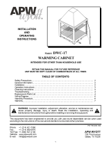
MODEL “FDD” or “FDDL” DUAL OVERHEAD WARMERS REPLACEMENT PARTS CATALOG
FDD or FDDL Followed by 18, 24, 30, 36, 42, 48, 54, 60, 66, 72, 84, or 96
FOR COMPLETE STYLE AND OPTION DESIGNATION:
ADD ONE SUFFIX FROM EACH FOLLOWING CATEGORY AFTER THE MODEL AND LENGTH
H=HIGH WATTAGE 1=120V I=INFINITE CONTROL
L=LOW WATTAGE 2=208V T=TOGGLE SWITCH
3=240V R=REMOTE CONTROL/SWITCH
A LIGHTED DUAL WARMER, 48” LONG, HIGH WATTAGE, 208V, WITH TOGGLE SWITCH = OHDL46H2T
WATTAGE VOLTAGE SWITCH
EXAMPLE:
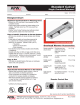
18 120V 800W 120V 880W 120V 500W 120V 580W
18 208V 800W 208V 862W 208V 500W 208V 562W
18 230V 735W 230V 809W 230V 588W 230V 662W
18 240V 800W 240V 880W 240V 640W 240V 720W
24 120V 1150W 120V 1230W 120V 700W 120V 780W
24 208V 1150W 208V 1212W 208V 700W 208V 762W
24 230V 1057W 230V 1130W 230V 643W 230V 717W
24 240V 1150W 240V 1230W 240V 700W 240V 780W
30 120V 1520W 120V 1600W 120V 900W 120V 980W
30 208V 1520W 208V 1582W 208V 900W 208V 962W
30 230V 1396W 230V 1470W 230V 827W 230V 901W
30 240V 1520W 240V 1600W 240V 900W 240V 980W
36 120V 1840W 120V 2000W 120V 1150W 120V 1310W
36 208V 1840W 208V 1964W 208V 1150W 208V 1274W
36 230V 1690W 230V 1837W 230V 1057W 230V 1204W
36 240V 1840W 240V 2000W 240V 1150W 240V 1310W
42 120V 2200W 120V 2360W 120V 1350W 120V 1510W
42 208V 2200W 208V 2324W 208V 1350W 208V 1474W
42 230V 2021W 230V 2168W 230V 1240W 230V 1387W
42 240V 2200W 240V 2360W 240V 1350W 240V 1510W
48 120V 2530W 120V 2690W 120V 1600W 120V 1760W
48 208V 2530W 208V 2654W 208V 1600W 208V 1724W
48 230V 2324W 230V 2471W 230V 1470W 230V 1617W
48 240V 2530W 240V 2690W 240V 1600W 240V 1760W
54 120V 2850W 120V 3010W 120V 1850W 120V 2010W
54 208V 2850W 208V 2974W 208V 1850W 208V 1974W
54 230V 2618W 230V 2765W 230V 1700W 230V 1846W
54 240V 2850W 240V 3010W 240V 1850W 240V 2010W
60 120V 3200W 120V 3440W 120V 2100W 120V 2340W
60 208V 3220W 208V 3406W 208V 2100W 208V 2286W
60 230V 2958W 230V 3178W 230V 1929W 230V 2150W
60 240V 3220W 240V 3460W 240V 2100W 240V 2340W
66 208V 3600W 208V 3786W 208V 2320W 208V 2506W
66 230V 3307W 230V 3527W 230V 2131W 230V 2352W
66 240V 3600W 240V 3840W 240V 2320W 240V 2560W
72 208V 3960W 208V 4146W 208V 2550W 208V 2736W
72 230V 3637W 230V 3858W 230V 2342W 230V 2563W
72 240V 3960W 240V 4200W 240V 2550W 240V 2790W
84 --- --- 208V 4100W 208V 4348W
84 --- --- 230V 3765W 230V 4059W
84 --- --- 240V 4100W 240V 4420W
96 --- --- 208V 4800W 208V 5040W
96 --- --- 230V 4408W 230V 4702W
96 --- --- 240V 4800W 240V 5120W
HIGH WATTAGE UNITS LOW WATTAGE UNITS
LENGTH FDD SERIES FDDL SERIES FDD SERIES FDDL SERIES
18
FDD or FDDL18 THRU 96 DUAL OVERHEAD WARMERS
ITEM PART NUMBER DESCRIPTION ITEM PART NUMBER DESCRIPTION
19
FDD or FDDL-18 Thru -96 EXPLODED VIEW
22
10
25
9
8
7
6
18
15
20
21
19
14
11
23
17
24
1
2
12
3
16
4
5
13
20
  • Page 1 1
  • Page 2 2
  • Page 3 3
  • Page 4 4
  • Page 5 5
  • Page 6 6
  • Page 7 7
  • Page 8 8
  • Page 9 9
  • Page 10 10
  • Page 11 11
  • Page 12 12
  • Page 13 13
  • Page 14 14
  • Page 15 15
  • Page 16 16
  • Page 17 17
  • Page 18 18
  • Page 19 19
  • Page 20 20

APW Wyott FD Operating instructions

Category
Food warmers
Type
Operating instructions

Ask a question and I''ll find the answer in the document

Finding information in a document is now easier with AI