
N i l e s A u d i o C o r p o r a t i o n
1 2 3 3 1 S . W . 1 3 0 S t r e e t M i a m i , F l o r i d a 3 3 1 8 6
P h o n e : 3 0 5 - 2 3 8 - 4 3 7 3 F a x : ( 3 0 5 ) 2 3 8 - 0 1 8 5
w w w . n i l e s a u d i o . c o m
©2008 Niles Audio Corporation. All rights reserved. Niles, Blending High Fidelity and Architecture and the Niles logos are
registered trademarks of Niles Audio Corporation. MicroPerf and Twist & Lock are trademarks of Niles Audio Corporation.
All other trademarks are the property of their respective owners. D S0 05 40 B
B L E N D I N G H I G H F I D E L I T Y A N D A R C H I T E C T U R E
®
TECHNICAL SUPPORT
IF YOU HAVE QUESTIONS ABOUT THE INSTALLATION OR OPERATION OF THIS OR ANY OTHER NILES PRODUCT,
PLEASE CALL OUR TECHNICAL SUPPORT DEPARTMENT AT 1-800-BUY-HIFI (1-800-289-4434). SUPPORT IS
AVAILABLE WEEKDAYS 8:00 A.M. TO 7:00 P.M. EASTERN TIME WITH THE EXCEPTION OF HOLIDAYS.
Model
Recommended
Amplifier Power
Normal
Impedance
Frequency
Response
Sensitivity
Frame
Dimensions
Hole Cut-Out
Dimensions
Depth Behind
Ceiling
CM953
Twist and Lock™
mechanism featuring
one 9" Injection-molded
TCC™ woofer with butyl
rubber surround and one
1-1/2" Teteron
®
fluid-
cooled midrange with one
1" Teteron fluid cooled
tweeter mounted in a
pivoting housing
10 to 200 watts
per channel
8 ohm
nominal;
6 ohm
minimum
44Hz - 22Hz
+/-3dB
90 dB with
2.83 V pink
noise input
measured
at 1 meter
on axis
12-3/4 inches
(32.4cm)
11-1/4 inches
(28.6cm)
5-3/4 inches
(14.6cm)
CM963
Twist and Lock™
mechanism featuring one
9" Interlaced glass fiber
woofer with butyl rubber
surround and one 1-1/2"
glass fiber fluid-cooled
midrange with one 1"
Teteron fluid cooled
tweeter mounted in a
pivoting housing
10 to 200 watts
per channel
8 ohm
nominal;
6 ohm
minimum
44Hz - 23Hz
+/-3dB
90 dB with
2.83 V pink
noise input
measured
at 1 meter
on axis
12-3/4 inches
(32.4cm)
11-1/4 inches
(28.6cm)
5-3/4 inches
(14.6cm)
SPECIFICATIONS
Figure 2. New construction bracket
Figure 4. Midrange/tweeter pod adjustment
Figure 1. Typical placement for stereo listening
Figure 3. Installing the loudspeaker
Figure 5. Treble level control
Figure 6. Midrange level control
CM953
CM963
I N S T A L L A T I O N G U I D E
H I G H P E R F O R M A N C E C E I L I N G L O U D S P E A K E R S

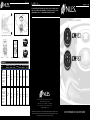
CONGRATULATIONS!
Thank you for choosing a CM953 or CM963 Ultra High Performance loudspeaker from Niles. With proper installation and operation, you will
enjoy years of trouble-free use. Niles manufactures the industry’s most complete line of custom installation components and accessories
for audio/video systems. To see the complete Niles product assortment, visit us on the Internet at: www.nilesaudio.com
PACKAGE CONTENTS
Each package contains one pair of CM953 or CM963 loudspeakers; 1 pair of Aluminum MicroPerf™ Grilles and 1 pair of cardboard paint
mask/hole cutout templates.
INSTALLATION CONSIDERATIONS
We recommend using the following tools and material to install your Niles CM loudspeaker:
Before starting the installation, please observe the following precautions:
RUNNING WIRES IN WALLS OR CEILINGS
When running loudspeaker wire inside walls or ceilings, use special jacketed cable (a minimum of 16-gauge two-conductor CL-2 or CL-3
rated loudspeaker wire) to protect the wire and for fire prevention. In some areas, conduit is also required. For a trouble-free installation,
low-voltage wire such as loudspeaker wire must be run in accordance with the National Electrical Code and any applicable provisions of
the local building code. If you are unsure of the correct installation techniques, wire jacket, or type of conduit to use, consult a professional
audio/video installer, building contractor, or the local building and inspection department.
SELECTING THE LOCATION FOR YOUR LOUDSPEAKERS
The CM900 series loudspeakers are designed to be installed in any standard ceiling. There are two considerations for placing the
loudspeaker; ease of running the cable to the loudspeaker and coverage of the loudspeaker. The best stereo effect will be achieved if both
the loudspeakers are at equal distance from the listener and closer together than the listener is from the loudspeakers. Avoid installing the
loudspeakers near corners to prevent a “boomy” or diffracted sound. The CM900 series loudspeakers will cover an area of a circle with a
16-foot diameter when mounted at an 8-foot height and pointed straight down. (See Figure 1)
EXISTING CONSTRUCTION INSTALLATION
IMPORTANT: BEFORE YOU CUT INTO ANY WALL, REVIEW THE PRIOR SECTION ON LOUDSPEAKER PLACEMENT WHEN SELECTING THE
LOCATION FOR YOUR LOUDSPEAKERS.
1. When determining the location of the loudspeaker cutout, keep in mind that the mounting dogs will extend 3/4” beyond the cutout.
Make sure that you do not place the edge of the cutout directly next to a ceiling joist. Locate the joists using a stud sensor or by hand
knocking. Use the supplied cutout template (remove the largest perforated circle and use cardboard square with hole as the template) to
determine how large of a hole you will need to cut. These templates are packed with your loudspeakers between the styrofoam packing
and the ends of the box.
2. Once you have determined a possible position for the cutout, drill a 1/8” pilot hole just barely through the ceiling (1/2” to 5/8” deep in
most homes) in the center of your proposed loudspeaker location.
BE VERY CAREFUL NOT TO DRILL THROUGH EXISTING WIRES, PIPES, OR STRUCTURE. IF YOU FEEL ANY EXTRA RESISTANCE AS YOU
ARE DRILLING, STOP.
3. Cut a foot-long piece of coat hanger. Bend the wire (creating a right angle) leaving 7” at one end (this allows for the extra width of the
mounting dogs). Poke the “L-shaped” wire into the pilot hole and turn it in a complete circle and move it into the ceiling cavity to make
sure you have approximately 5-7/8” of depth. If the wire’s movement is obstructed by anything, fill the hole(s) with spackle and try
another location.
4. If the coat hanger moves freely in a complete circle and you have sufficient depth, hold the template up to the ceiling surface. The
cardboard square with the circular hole is the template. The inner perforated circle within the larger circle that was removed in step
1 earlier is the paint mask. Keep it for painting the loudspeaker later. Outline the circular cutout on the ceiling surface lightly with a
pencil. Drill the starting point of your cut with a 1/4” bit.
5. If you are cutting drywall use a sheetrock or keyhole saw, cut the hole with the saw at a 45° angle. That way the drywall section can be
replaced cleanly if there is an unseen obstruction behind the wall.
IMPORTANT: BE VERY CAREFUL NOT TO SAW THROUGH EXISTING WIRES, PIPES, OR STRUCTURE.
IF YOU FEEL EXTRA RESISTANCE AS YOU ARE CUTTING, STOP.
NEW CONSTRUCTION INSTALLATION
INSULATING THE WALL CAVITY
If feasible, fill the wall cavity with insulation at this point.
MOUNTING THE NEW CONSTRUCTION BRACKET
The optional CM900 BKT can be used with the CM953 or CM963 loudspeakers. The hole saving bracket enables a faster and cleaner
final installation of the loudspeaker. It forces the drywall installer to cut out the loudspeaker hole for you and provides wire ties for the
loudspeaker wire, reducing the risks of accidental loss or movement of the wire. In addition, it enables you to align your loudspeakers with
other ceiling fixtures with great accuracy since you can really see exactly where the loudspeaker will be. To install the bracket, first pivot
the long wing out until it stops, which will be in straight line with the short wing. The wings and brackets have centering lines to simplify
placement of the loudspeakers. Screw one side of the assembled bracket with wings to the joist using one of the supplied screws. Level
the bracket. Screw the other side of the bracket/wing assembly to the joist. Two screws on each side make for a very secure installation.
Secure the wire to the bracket using bracket’s wire tie tab. The drywall installers will cut the drywall to the exact size of the bracket.
(See Figure 2)
CONCEALING LOUDSPEAKER WIRE FOR A FUTURE INSTALLATION
Attach the loudspeaker wire in a loop between the ceiling joists and carefully mark the exact location of the wire on a set of plans. Ask the
general contractor to inform the drywall installers that the loudspeaker wire loops are concealed for future installations.
UNPACKING AND FINAL INSTALLATION
1. Remove the top piece of styrofoam from the box. You will find two loudspeakers bagged in a lower portion of packing. Remove the
loudspeaker from the bag. The metal grille is installed on the loudspeaker and will need to be removed. This is easily done by pulling on
the small black fabric strap.
2. Remove the loudspeaker module from the frame by turning the loudspeaker assembly counter-clockwise using the two tabs provided.
Place the loudspeaker assembly to the side when removed for installation after the frame has been mounted. Take care to place it so
that the woofer, tweeter or crossover on the rear are not damaged. (See Figure 3) DO NOT place loudspeaker assembly face-down.
3. Insert the frame into the hole by carefully holding it with both hands and angling it slowly into the hole until the frame is flush with the
ceiling. Holding it in place carefully with one hand, use a cordless drill to begin mounting the frame.
4. Tighten the four ‘dog’ screws using an extended length #2 Phillips bit or a standard #2 Phillips bit in a 1/4” bit holder. Use low torque and
low speed or you may damage the frame. This should pull the frame and mounting dog together (sandwiching the drywall) so that the
frame is absolutely flush with the wall surface. There should be no gaps between the wall and the frame.
IMPORTANT: DO NOT OVER TIGHTEN THE SCREWS! OVER TIGHTENING THEM MAY MAKE THE GRILLE DIFFICULT TO INSTALL
5. At each loudspeaker location, route the wire through the installed frame, then separate the loudspeaker wire so that at least 2 inches of
each conductor are free. Strip away 1/4 inch of insulation from each individual loudspeaker wire.
6. Retrieve the loudspeaker module removed from the frame in step 2.
7. Press down each spring-loaded connector one at a time, insert the appropriate conductor and then release the connector. Check to be
sure that the connector is making contact with stripped wire and not the wire jacket. Gently tug on the loudspeaker wire to make sure it
is held in place. If not, repeat this procedure until it is.
IMPORTANT: OBSERVE CORRECT POLARITY: POSITIVE (+) GOES TO THE RED POST AND NEGATIVE (–) GOES TO THE BLACK POST.
8. Insert the loudspeaker module into the frame by carefully holding it with both hands and angling it slowly into the frame until the module
is seated in the frame. Holding it in place, carefully use the same tabs used to remove it from the frame to turn it clockwise until you feel
a ‘click’, which should be approximately an 1/8th of a turn. Take care not to push against the woofer or the midrange/tweeter pod as you
are inserting the loudspeaker module.
9. Direct the midrange/tweeter pod. The pod is directed by gently pressing on the outer edge of the housing. It will move in any direction.
For critical listening, direct the tweeter towards the user’s favorite listening position. For surround sound or low volume background
listening, create more reflections and thus more ambiance by directing the tweeter towards the sidewalls. (See Figure 4)
10. Set the Treble level control. Listen to a well-recorded piece of music at the user’s favorite listening position. Listen for treble harshness
or ringing, particularly when the loudspeakers are placed in a room without carpet. Use the -3dB Treble cut position to correct. Listen
for dull or muffled upper frequencies, particularly when the loudspeakers are installed in an area with thick carpet or fabric wall
coverings. Use the +3dB Treble boost position to correct. (See Figure 5)
11. Set the Midrange level control. Listen to a well-recorded piece of music at the user’s favorite listening position. Listen for thin response
in the vocal range. Use the +3dB Midrange boost position to correct. Use the –3dB Midrange cut position if vocals or instruments in this
range are too prominent. (See Figure 6)
12. Set the Boundary Compensation control. If the CM953 or CM963 loudspeaker is installed placed in a position where the loudspeaker is
closer than 2 to 3 feet from a room boundary, such as a wall, and the sound is ‘boomy’, please remove the loudspeaker module from
the frame and switch the rear-mounted Boundary Compensation switch on. You may need to also adjust the Midrange level when using
this switch.
13. Install the MicroPerf grille. Start by positioning one edge of the grille slightly inside the loudspeaker. Gently work around the
loudspeaker a little at a time until the grille is fully seated. Don’t try to insert the grille fully in any one area, as this will make complete
installation more difficult. Don’t force the grille to fit as you may damage the grille if you apply too much force.
14. Connect the other end of each loudspeaker wire to the receiver or amplifier carefully observing polarity.
15. Turn on the receiver or amplifier and test all loudspeakers in the system.
PAINTING THE GRILLE AND FRAME
Each CM953 or CM963 loudspeaker frame and flush-mount metal grille may be painted without the need for primer. The frame may be
painted prior to installation if desired.
1. Install loudspeaker frame into ceiling or wall following the previous steps 1 - 4.
2. Paint the frame of the loudspeaker.
3. Paint the grille separately from the loudspeaker frame. For best results when painting the grille, use a spray gun or airless sprayer. Thin
the paint to prevent clogging of the grille holes and apply several light coats instead of one heavy one.
4. Finish installation of the loudspeaker following the previous steps 5-15.
PAINTING INSTRUCTIONS IF FRAME AND LOUDSPEAKER MODULE ARE INSTALLED
1. Remove the smallest perforated circle from the cardboard square template. This is the paint mask that protects the loudspeaker from
paint. Gently press it into place inside the baffle.
2. Paint the frame of the loudspeaker.
3. Paint the grille separately from the loudspeaker frame. For best results when painting the grille, use a spray gun or airless sprayer. Thin
the paint to prevent clogging of the grille holes and apply several light coats instead of one heavy one.
4. Gently remove the paint mask after paint has dried by pressing in the tab in the center and carefully pulling out the mask with your
finger. Be very careful not to poke the tweeter with your finger.
5. Finish installation of the loudspeaker following the previous steps 9-15.
• Cordless drill with 1/4 – and 1/2-
inch drill bits and a 1-inch paddle
drill bit (for drilling through studs)
• Stiff wire, fish tape or glow rods
for routing cables
• Rubber gloves and protective
eyewear
• Keyhole or drywall saw
• Phillips screwdriver set
• Wire stripper
• Stud finder
• Cable ties
• Pencil
• Turn off all system power before
making any connections
• Always wear protective eyewear
when using tools
• Make sure hands are clean before
installation
• Wear gloves when working with
fiberglass insulation
-
 1
1
-
 2
2


Ask a question and I''ll find the answer in the document
Finding information in a document is now easier with AI
Related papers
Other documents
-
Strong SM-RBX-14-WH Template
-
Extron SMB 303 Template
-
Niles Audio CM850Si User manual
-
-
-
Rod Desyne WIC1920-12 Installation guide
-
-
-
-
Artsound FL-550 Datasheet