4
Post Hole Digger Storage Stand Assembly Instructions Manual No. 317-189M 10/06/08
Land Pride
PD15, PD25, & PD35 Assembly
■
PD15, PD25, & PD35 Assembly
Part No. 317-142A
A detailed listing of parts for this accessory kit is
provided on page 5. Use the list as a checklist to
inventory parts received. Please contact your local
Land Pride dealer for any missing hardware.
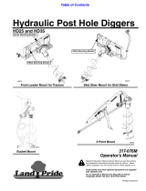
Refer to Figure 2 on page 1:
The optional storage stand may be used when the
PD15, PD25, and PD35 Post Hole Digger is not in
operation. It will help prolong digger’s life by keeping
theunitoffthegroundwheremoistureanddebrisare
more likely to collect causing undue damage to the
digger. Also, the storage stand design aids in
mounting and dismounting the Post Hole Digger to
and from the tractor.
PD15, 25, & 35 Storage Stand
Assembly
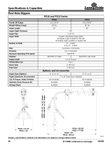
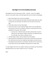
Refer to Figure 4:
TheStorage Stand Assembly consists of an A-frame
storage stand (#4), clamping knobs (#11), cradle
(#5), and a bag of (4) - 3/8”-16 x 1” long GR5 bolts:
1. Unscrew locknuts (#8) and remove
1/2"-13 x 3 1/2" GR5 hex head bolts (#7). Slide
auger (#13) off of gearbox output shaft.
2. Remove existing hex head cap screws (#6),
lockwashers (#10) and flat washers (#9) from
undersideof gearbox.Remove auger guard (#1).
3. Position cradle (#5) between auger guard (#1)
and gearbox (#12). Make sure cradle pins (#3)
are positioned to the back as shown.
4. Use four new hex head bolts (#6), lock
washers(#10) and flat washers(#9) in hardware
bag to attach cradle (#5) and existing guard (#1)
to gearbox (#12).
5. Reattach auger to gearbox output shaft with
existing auger bolts (#7) and locknuts (#8).
PD15, 25, & 35 Storage Stand
Operation
Refer to Figure 4:
Loweraugertiptothegroundatthelocationyouplan
to disconnect the Post Hole Digger from the tractor.
Set tractor park brakes, turn tractor engine off, and
remove ignition key before dismounting tractor.
Always chock tractor wheels for an extra measure of
safety if you stop on a gentle slope.
Attach storage stand (#4) to cradle (#5).
1. Makecertain guide slots (#2) at end of storage stand are
securely positioned over cradle pins (#3). Secure
storage stand to cradle with clamping knobs (#11).
2. Without starting the tractor, lower boom (#14) to rest
yoke hitchpins securelyin supportangleson thestorage
stand. Some adjustment to the support angles may be
required.
3. Disconnect 3-point hitch.
4. Start tractor and drive away being careful not to catch on
the Post Hole Digger and Storage Stand.
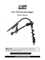
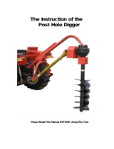
PD15, 25, and 35 Storage Stand Assembly
Figure 4
NOTE: Do not disconnect Post Hole Digger from a
tractor on a steep slope. Injury to personnel and
equipment may result.
20872