Page is loading ...

Before attempting to connect or operate this product, please read these
instructions carefully and save this manual for future use.
No model number suffix is shown in this manual.
This illustration represents WV-CP500.
Lens: Option
Installation Guide
Color CCTV Camera
Model Nos. WV-CP500
WV-CP504

2
CAUTION: TO REDUCE THE RISK OF ELECTRIC SHOCK,
DO NOT REMOVE COVER (OR BACK).
NO USER-SERVICEABLE PARTS INSIDE.
REFER SERVICING TO QUALIFIED SERVICE PERSONNEL.
CAUTION
RISK OF ELECTRIC
SHOCK DO NOT OPEN
The lightning flash with arrow-
head symbol, within an equilat-
eral triangle, is intended to alert
the user to the presence of unin-
sulated "dangerous voltage"
within the product's enclosure
that may be of sufficient magni-
tude to constitute a risk of elec-
tric shock to persons.
The exclamation point within an
equilateral triangle is intended to
alert the user to the presence of
important operating and mainte-
nance (servicing) instructions in
the literature accompanying the
appliance.
WARNING:
• This apparatus must be earthed.
• Apparatus shall be connected to a mains sock-
et outlet with a protective earthing connection.
• The mains plug or an appliance coupler shall
remain readily operable.
• To prevent fire or electric shock hazard, do not
expose this apparatus to rain or moisture.
• The apparatus should not be exposed to drip-
ping or splashing and that no objects filled with
liquids, such as vases, should be placed on the
apparatus.
• All work related to the installation of this prod-
uct should be made by qualified service per-
sonnel or system installers.
• The connections should comply with local elec-
trical code.
The model number and serial number of this
product may be found on the surface of the unit.
You should note the model number and serial
number of this unit in the space provided and
retain this book as a permanent record of your
purchase to aid identification in the event of
theft.
Model No.
Serial No.
NOTE: This equipment has been tested and
found to comply with the limits for a Class A digital
device, pursuant to Part 15 of the FCC Rules.
These limits are designed to provide reasonable
protection against harmful interference when the
equipment is operated in a commercial environ-
ment. This equipment generates, uses, and can
radiate radio frequency energy and, if not
installed and used in accordance with the instruc-
tion manual, may cause harmful interference to
radio communications.
Operation of this equipment in a residential area
is likely to cause harmful interference in which
case the user will be required to correct the inter-
ference at his own expense.
FCC Caution: To assure continued compliance,
(example - use only shielded interface cables
when connecting to computer or peripheral devic-
es). Any changes or modifications not expressly
approved by the party responsible for compliance
could void the user’s authority to operate this
equipment.
For U.S.A
For U.S.A
This Class A digital apparatus complies with
Canadian ICES-003.
For Canada
Power disconnection. Unit with or without ON-OFF
switches have power supplied to the unit whenever
the power cord is inserted into the power source;
however, the unit is operational only when the ON-
OFF switch is in the ON position. Unplug the power
cord to disconnect the main power for all units.

3
Important safety instructions
1) Read these instructions.
2) Keep these instructions.
3) Heed all warnings.
4) Follow all instructions.
5) Do not use this apparatus near water.
6) Clean only with dry cloth.
7) Do not block any ventilation openings. Install in accordance with the manufacturer's
instructions.
8) Do not install near any heat sources such as radiators, heat registers, stoves, or other
apparatus (including amplifiers) that produce heat.
9) Do not defeat the safety purpose of the polarized or grounding-type plug. A polarized plug
has two blades with one wider than the other. A grounding type plug has two blades and a
third grounding prong. The wide blade or the third prong are provided for your safety. If the
provided plug does not fit into your outlet, consult an electrician for replacement of the
obsolete outlet.
10) Protect the power cord from being walked on or pinched particularly at plugs, convenience
receptacles, and the point where they exit from the apparatus.
11) Only use attachments/accessories specified by the manufacturer.
12) Use only with the cart, stand, tripod, bracket, or table specified by the manufacturer, or
sold with the apparatus. When a cart is used, use caution when moving the cart/apparatus
combination to avoid injury from tip-over.
13) Unplug this apparatus during lightning storms or when unused for long periods of time.
14) Refer all servicing to qualified service personnel. Servicing is required when the apparatus
has been damaged in any way, such as power-supply cord or plug is damaged, liquid has
been spilled or objects have fallen into the apparatus, the apparatus has been exposed to
rain or moisture, does not operate normally, or has been dropped.
S3125A

4
Limitation of liability
THIS PUBLICATION IS PROVIDED "AS IS"
WITHOUT WARRANTY OF ANY KIND,
EITHER EXPRESS OR IMPLIED, INCLUDING
BUT NOT LIMITED TO, THE IMPLIED
WARRANTIES OF MERCHANTABILITY,
FITNESS FOR ANY PARTICULAR PURPOSE,
OR NON-INFRINGEMENT OF THE THIRD
PARTY'S RIGHT.
Disclaimer of warranty
IN NO EVENT SHALL Panasonic Corporation
BE LIA BL E TO ANY PART Y OR ANY
PERSON, EXCEPT FOR REPLACEMENT OR
REASONABLE MAINTENANCE OF THE
PRODUCT, FOR THE CASES, INCLUDING
BUT NOT LIMITED TO BELOW:
(1) ANY DAMAGE AND LOSS, INCLUDING
WITHOUT LIMITATION, DIRECT OR
INDIRECT, SPECIAL, CONSEQUENTIAL
OR EXEMPLARY, ARISING OUT OF OR
RELATING TO THE PRODUCT;
(2) PERSONAL INJURY OR ANY DAMAGE
CAUSED BY INAPPROPRIATE USE OR
NEGLIGENT OPERATION OF THE USER;
(3) U N A U T H O R I Z E D DIS A S S E M B L E ,
REPAIR OR MODIFICATION OF THE
PRODUCT BY THE USER;
(4) INCONVENIENCE OR ANY LOSS ARIS-
ING WHEN IMAGES ARE NOT DIS-
PLAYED, DUE TO ANY REASON OR
CAUSE INCLUDING ANY FAILURE OR
PROBLEM OF THE PRODUCT;
(5) ANY PROBLEM, CONSEQUENTIAL
INCONVENIENCE, OR LOSS OR DAM-
AGE, ARISING OUT OF THE SYSTEM
COMBINED BY THE DEVICES OF THIRD
PARTY.
THIS PUBLICATION COULD INCLUDE
T E C H N I C A L I N A C C U R A C I E S O R
TYPOGRAPHICAL ERRORS. CHANGES ARE
ADDED TO THE INFORMATION HEREIN, AT
ANY TIME, FOR THE IMPROVEMENTS OF
T H I S P U B L I C AT I O N A N D / O R T H E
CORRESPONDING PRODUCT (S).

5
Preface
This product is a 1/3-inch type {1/3"} CCD color CCTV camera. Connection of this product to a
video monitor allows users to use this product as a monitoring camera.
• WV-CP500:120VACpowersupply
• WV-CP504:24VAC,12VDCpowersupply
Introduction of SUPER-D5 (super dynamic function)
Integration of SUPER-D5 into the CCD and signal processing circuit has achieved approximate-
ly 128 times higher dynamic range as compared with conventional camera. Thanks to the inte-
gration of the darkness compensation function, a subject on which much illuminance difference
exists resulting from bright and dark areas can be naturally displayed in an image.
Introduction of newly developed high-resolution CCD
The introduction of the newly developed CCD with 976 of horizontal pixels has led to the hori-
zontal resolution of as high as 650 TV lines (typ.).
Auto back focus function (ABF) equipped
Moving the CCD inside the camera to an optimal position with the operation button of this unit
or the setup menu allows users to automatically adjust the back focus.
The back focus is adjustable with the setup menu through the system controller (option) even
after installation of this unit.
The auto back focus function also allows users to correct out of focus when changing between
color and black-and-white images.
High sensitivity achieved thanks to noise reduction function
Minimum illumination 0.3 lx (F1.4) has been accomplished for color images thanks to the intro-
duction of low noise circuit design.
Night monochrome image activation function equipped
No operation is required at night because the image automatically changes from the color
mode to the black-and-white mode at low illuminance.
Intelligent VMD (i-VMD) functions of motion detection and object abandonment/removal
detection equipped
The motion and abandonment/removal of an object are detectable.
The states of covering the camera with a cloth, a cap or others and changing the camera direc-
tion notably can be detected (interference detection).
The detection resolution has been significantly improved as compared with a conventional
type, and the introduction of the newly developed detection method has improved detection
accuracy under the condition that the motion detection is prone to malfunction due to leaves
swaying.
Note:
• The i-VMD function is not the dedicated function to prevent thefts, fires, etc. We are not
responsible for any accidents or damages occurring in case.

6
About the user manuals
Trademarks and registered trademarks
The operating instructions of the camera consist of 2 sets: this book and operating instructions
(PDF).
This book explains how to install the camera.
Refer to the "Operating Instructions (PDF)" on the provided CD-ROM for descriptions of how to
perform the unit settings. Adobe
®
Reader
®
is required to read PDF. When the Adobe
®
Reader
®
is not installed on the PC, download the latest Adobe
®
Reader
®
from the Adobe web site and
install it.
Adobe and Reader are either registered trademarks or trademarks of Adobe Systems
Incorporated in the United States and/or other countries.

7
Contents
Important safety instructions....................................................................................................... 3
Limitation of liability .................................................................................................................... 4
Disclaimer of warranty ................................................................................................................ 4
Preface ....................................................................................................................................... 5
About the user manuals.............................................................................................................. 6
Trademarks and registered trademarks ..................................................................................... 6
Precautions................................................................................................................................. 8
Major operating controls and their functions............................................................................... 9
Precautions for installation ......................................................................................................... 12
Installation and connection ......................................................................................................... 14
Optional dedicated lens ......................................................................................................... 14
External synchronization switch............................................................................................. 18
Setup menu ................................................................................................................................ 22
List of setup menu .................................................................................................................... 22
Basic operation ........................................................................................................................ 24
Screen transition diagram ........................................................................................................ 26
Troubleshooting .......................................................................................................................... 27
Specifications ............................................................................................................................. 29
Standard accessories ................................................................................................................. 30

8
Precautions
This product has no power switch.
Power is supplied from an external 12 V DC/
24 V AC (WV-CP504) or 120 V AC (WV-
CP500) power-supply device. Refer to ser-
vice personnel for how to turn on/off the
power.
Use this product for indoor use only.
Do not expose this product to direct sunlight
for hours and do not install the product near
a heater or an air conditioner. Otherwise, it
may cause deformation, discoloration and
malfunction. Keep this product away from
water.
To keep on using with stable performance
• Partsofthisproductmaydeteriorateand
it may shorten lifetime of this product
when using in locations subject to high
temperatures and high humidity. Do not
expose this product to direct heat sourc-
es such as a heater.
• Use this product at temperatures within
–10 °C to +50 °C {14 °F to 122 °F}, and
humidity below 90 % (when using this
product without turning the power off).
Do not rub the edges of metal parts with
your hand.
Failure to observe this may cause injury.
Do not attempt to disassemble this prod-
uct.
To prevent electric shock, do not remove
screws or covers.
There are no user-serviceable parts inside.
Ask qualified service personnel for servicing.
Handle this product with care.
Do not abuse this product. Avoid striking,
shaking, etc. The product could be damaged
by improper handling or storage.
Cleaning this product body
Turn the power off when cleaning the prod-
uct. Use a dry cloth to clean this product. Do
not use strong abrasive detergent when
cleaning this product. When the dirt is hard
to remove, use a mild detergent and wipe
gently. Then, wipe off the remaining deter-
gent with a dry cloth.
Otherwise, it may cause discoloration. When
using a chemical cloth for cleaning, read the
caution provided with the chemical cloth
product.
Noise on monitor
This product is equipped with a super sensi-
tive CCD. Therefore, white dot noise may
appear on the monitor. This phenomenon is
not trouble.
Discoloration on the CCD color filter
When continuously shooting a bright light
source such as a spotlight, the color filter of
the CCD may have deteriorated and it may
cause discoloration. Even when changing the
fixed shooting direction after continuously
shooting a spotlight for a certain period, the
discoloration may remain.
Do not aim this product at strong light
sources.
A light source such as a spot light causes a
blooming (light bleeding) or a smear (vertical
lines).
Turn the circuit breaker off which supplies
this product with the power when abnor-
mal conditions are encountered.
Smear
Bright subject
Blooming

9
Major operating controls and their functions
(UP)
(LEFT)
(RIGHT)
(DOWN)
(SET)
NEAR
FAR
BF/MENU
Side view (WV-CP500)
Side view (WV-CP504)
ALC lens connector
Inside the side cover
(Slide the cover leftward to the lock position.)
Operation buttons*
: Up button (UP)
: Down button (DOWN)
: Left button (LEFT), NEAR
: Right button (RIGHT), FAR
: Setting button (SET), BF/MENU
Tripod mount base
Side cover
ALC lens connector
Tripod mount base
* The following names are assigned to
each button in this book:

10
POWER
ALARM OUT
ALARM IN
GND
VIDEO OUT
120V ~ 60Hz
Operation buttons*
: Up button (UP)
: Down button (DOWN)
: Left button (LEFT), NEAR
: Right button (RIGHT), FAR
: Setting button (SET), BF/MENU
* The following names are assigned to
each button in this book:
ALARM OUT
ALARM IN
POWER
VIDEO OUT
24V IN~
1-L
12V IN
NC
2-N
GND
(UP)
(LEFT)
(RIGHT)
(DOWN)
(SET)
NEAR
FAR
BF/MENU
GND
Rear view (WV-CP500)
Rear view (WV-CP504)
External terminal
Power indicator
Power connector
External terminal
Power indicator
AC/DC power terminal
Video output connector
Video output connector

11
Side cover (only for WV-CP500)
When the operation buttons are used, the
side cover is slide leftward to the lock posi-
tion.
ALC lens connector
The ALC connector is connected to this ALC
lens connector.
Tripod mount base
This socket is used to mount the camera
mount bracket (option). The tripod socket
can be mounted on either top or bottom of
the camera head.
(Tripod socket hole: 1/4-20 UNC for tripod)
Operation buttons
This buttons are used to perform various set-
tings in the setup menu.
Video output connector
The Coaxial cable (locally procured) is con-
nected to this video output connector.
Power indicator
This indicator lights up when the power is on.
External terminal (☞ page 18)
Power connector (only for WV-CP500)
The included power cord is connected to this
power connector.
AC/DC power terminal
(only for WV-CP504)
The power supply of 24 V AC or 12 V DC is
connected to this terminal.

12
Precautions for installation
This camera is designed to be used
indoors. This camera is not operable out-
doors.
Do not operate this product beyond the
specified temperature, humidity or power
source ratings.
Use this product at temperatures within
–10 °C to +50 °C {14 °F to 122 °F}, and
humidity below 90 %.The input power source
is 12 V DC/24 V AC (WV-CP504) or 120 V AC
(WV-CP500).
Installing place
Contact your dealer for assistance if you are
unsure of an appropriate place in your partic-
ular environment.
• Make sure that the installation area is
strong enough to hold the camera, such
as a concrete ceiling.
• If a ceiling board such as plaster board
is too weak to support the total weight,
the area shall be sufficiently reinforced.
• Do not install this productin a humid or
dust-laden environment.
Otherwise, lifetime of the internal parts
may be shortened.
Avoid installing in the following locations.
• Locationswhereitmaygetwetfromrain
or water splash
• Locations where a chemical agent is
used such as a swimming pool
• Locationssubjecttosteamandoilsmoke
such as a kitchen, Locations near flam-
mable gas or vapor
• Locations whereradiation or x-ray emis-
sions are produced
• Locations subject to strong magnetic
field or radio waves
• Locations where corrosive gas is pro-
duced
• Locations whereit may be damaged by
briny air such as seashores
• Locations where the temperature is not
within –10 °C to +50 °C {14 °F - 122 °F}.
• Locations subject to vibrations (This
product is not designed for on-vehicle
use.)
• Locationssubjecttocondensationasthe
result of severe changes in temperature
Avoid installing the camera in a place with
a high level of noise.
Installation near an air conditioner, an air
cleaner, a vending machine, or the like
causes noise.
Avoid connections during a lightning
storm.
Otherwise, an electric shock may be caused.
Be sure to remove this product if it is not
in use.
Keep the camera cable away from the
lighting cable.
Failure to observe this may cause noise.
Radio interference
When the camera is used near TV/radio
antenna, strong electric field or magnetic
field (near a motor or a transformer), images
may be distorted and noise sound may be
produced.
Mounting screws
• Screws are not supplied with this prod-
uct.
• Prepare them according to the material
and strength of the area where the prod-
uct is to be installed.
• Do not use an impact driver. Use of an
impact driver may damage the screws.
• Thescrewsandboltsmustbetightened
with an appropriate tightening torque
according to the material and strength of
the installation area.

13
Power cord (only for WV-CP500)
Connect the power cord securely. Run the
power cord so that no load is applied to the
cord when panning or tilting the camera.
(Failure to observe this may disconnect the
power cord, and accordingly no image is dis-
played.)

14
Installation and connection
z Rotate the lens (option) clockwise slowly to mount the lens.
Important:
• ForuseofC-mountlens,usetheC-mountadaptor(option).
• Forpreventionofdamagetothecamerabody,usealenswithprotrusionof5.5 mm {7/32"}
or less from the flange surface.
Optional dedicated lens
Protrusion from flange:
5.5 mm {7/32"} or less
Protrusion from mount:
ø20 mm {25/32”} or less
Cautions:
• ONLYCONNECTWV-CP504TO24VACOR12VDCCLASS2POWERSUPPLY.
• BesuretoconnectthegroundingleadtotheGNDterminal.
Lens type Model Nos.
ALC lens for 1/3 inch CCD cameras 2x vari-focal
8x vari-focal
15x motorized zoom
WV-LZA61/2S
WV-LZA62/2
WV-LZ62/8S
WV-LZ61/15

15
ALC lens connector
1 3
2 4
Screws (locally
procured)
Screws (locally
procured)
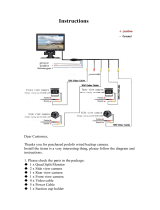
<Installation sample on a ceiling>
Camera mount
bracket (option)
x Connect the lens cable to the ALC lens connector of the camera.
Pin No.
1 Brake @
2 Brake !
3 Drive !
4 Drive @
c Secure the camera mount bracket
(option) to an installation position, and
mount the camera on the camera mount
bracket.
Important:
• If the total weight of the camera and lens
exceeds 1 kg {2.2 lbs.}, use a housing to take
measures against camera drop.
• Prepare mounting screws according to the
material of the area where the camera mount
bracket (option) is to be installed. The instal-
lation method may be different depending on
the material of the area where the bracket is
to be installed.
• Wheninstallingonsteel:
Fix with bolts and nuts (M6 or M8).
• Wheninstallingonconcrete:
Fix with anchor bolts or AY plug bolts (M6
or M8).
Recommended tightening torque (M6):
5.0 N·m {3.69 lbf·ft}
Recommended tightening torque (M8):
6.2 N·m {4.57 lbf·ft}

16
• Themountingconditionsofthecameramountbracketaredescribedasfollows:
For some applicable mount brackets, "A" is attached to the model number. The mounting condi-
tions are the same even for the A-attached models.
Installation
place
On ceiling
On wall
Applicable mount
bracket
WV-7011
WV-7010
Recommended
screw
M6
M8
Number of
screw
4 pcs.
3 pcs.
Minimum pull-out
strength (per 1 pc.)
196 N {44.06 lbf}
196 N {44.06 lbf}
WV-7012 M6 3 pcs. 196 N {44.06 lbf}
WV-831 M8 4 pcs. 921 N {207.05 lbf}
WV-7013 M6 3 pcs. 2.25 kN {505.82 lbf}
Tripod socket
hole: 1/4-20
UNC for tripod
Tripod mount
base
Mounting
screws
• Whenattachinganoptionaltripodmount
base on the bottom of the camera, use
the removed screws to attach the tripod
mount base. Use of longer or shorter
screws may cause drop or damage.
Recommended tightening torque:
0.39 N·m {0.29 lbf·ft}

17
v The video output cable is connected to this video output connector.
Important:
• Besuretoturnoffthepowerofeachdevicebeforeconnection.
• Besuretosecurethecoaxialcableconnectors.
Connect a coaxial cable to the video output connector.
b Use a cable tie (locally procured) to attach the coaxial cable to the camera mount
bracket.
Important:
• Thecabletieshallbemadeofmetallicordurablematerialtobestrongenoughbecause
the tie plays the role of camera drop prevention measures in case.
• When the cameramount bracket ismounted on awall, be sureto observe the mounting
height described on the illustration above.
POWER
ALARM OUT
ALARM IN
GND
VIDEO OUT
120V ~ 60Hz
To video input
Coaxial cables
WV-CP500
Camera mount
bracket (option)
The cable shall be
tied to the camera
mount bracket to
avoid slack.
The cable shall be
tied to the camera
mount bracket to
avoid slack.
Camera mount
bracket (option)
More than
270 cm {8.9'}
<Installation sample on a ceiling> <Installation sample on a wall>
Floor

18
External synchronization switch
The settings of the alarm input/output are configured on the SETUP menu.
Refer to the network operating instructions (PDF) for further information.
Important:
• Besuretoturnoffthepowerofeachdevicebeforeconnection.
Alarm output
Input specification: Open collector out-
put (max. voltage: 16 V DC)
Off: Internally pulled up
2 V to 4 V DC
On: Output voltage 1 V DC or less (max.
drive current: 100 mA)
Functions: Alarm output
Black-and-white switching output
Alarm input
Input specification: No-voltage make
contact input (3 to 5 V DC, internally
pulled up)
Off: Open or 3 to 5 V DC
On: Make contact with GND (required
drive current: 0.2 mA or more)
Functions: Alarm input
VMD enabling input
Color/BW switching input
Scene file switching input
* When an external device is connected, exercise care to avoid exceeding the rating.
* Applicable wire: 22 AWG-28 AWG, solid wire/stranded wire
Strip the end 9 mm to 10 mm {11/32" to 13/32"} of the wire and
insert it.
POWER
ALARM OUT
ALARM IN
GND
VIDEO OUT
120V ~ 60Hz
WV-CP500
9 mm - 10 mm
{11/32" to 13/32"}
ALARM OUT (Alarm output)
ALARM IN (Alarm input)
GND
The external terminal is the same between
WV-CP500 and WV-CP504.
Stripped
POWER
ALARM OUT
ALARM IN
GND
VIDEO OUT
120V ~ 60Hz
WV-CP500
9 mm - 10 mm
{11/32" to 13/32"}
ALARM OUT (Alarm output)
ALARM IN (Alarm input)
GND
The external terminal is the same between
WV-CP500 and WV-CP504.
Stripped

19
n Turn on the power.
WV-CP500
The included power cord is connected to this power connector.
Connect between the power connector on the rear side of the camera and a plug socket
with the supplied power cord.
POWER
ALARM OUT
ALARM IN
GND
VIDEO OUT
120V ~ 60Hz
120 V AC 60 Hz
Power cord (accessory)
WV-CP504
Important:
• Thepower supply of 24VAC/12 V DC shall
be insulated against 120 V AC.
• The power supply is automatically selected
either 24 V AC or 12 V DC. No setting is
required with this camera.
q Loosen the screw of the power cord plug
(accessory).
w Connect the power supply (option) of 24 V
AC or 12 V DC to the power cord plug.
Strip the end of the wire by 3 mm to 7 mm
{1/8" to 1/4"}, and twist the stripped part of
the wire sufficiently to avoid short circuit.
• Specificationofcable(wire)
AWG #16 - #28, Single core, twisted
* Check whether the stripped part of the
wire is not exposed and is securely con-
nected.
<Ratings>
AC 24 V DC 12 V
2-N @ (GND)
GND NC
1-L !
e Tighten the screw of the power cord plug.
r Connect the power cord plug to the AC/DC
power terminal on the rear side of the camera.
* Make sure that the power cord plug is inserted fully into the AC/DC power supply terminal.
ALARM OUT
ALARM IN
POWER
VIDEO OUT
24V IN~
1-L
12V IN
NC
2-N
GND
(UP)
(LEFT)
(RIGHT)
(DOWN)
(SET)
NEAR
FAR
BF/MENU
GND
To 24 V AC/12 V DC
power supply
C B A
Power cord plug
(accessory)
Stripped
Approx. 3 mm - 7 mm
{1/8" to 1/4"}

20
m Adjust the camera angle by loosening the screw of the camera mount bracket
while viewing the video monitor.
Be sure to loosen the screw of the camera mount bracket when the camera angle is adjust-
ed. If the camera angle is changed when the screw is tight, excessive force is applied to
the camera mount bracket and camera, and accordingly they may be damaged. Be sure to
tighten the screw securely after camera angle adjustment.
, Adjust the focus.
To use the varifocal lens/zoom lens
• Reset the back focus position to the CS mount default position before the back focus
adjustment (Press the right and left buttons simultaneously for more than 2 seconds, or
move the cursor to "MANUAL-ADJ" of "BACK-FOCUS" in the setup menu and press the
right and left buttons simultaneously for more than 2 seconds after pressing the setting but-
ton.).
• Beawarethattheadjustmentmethodvarieswithvarifocal lens or zoomlensmodels.For
further information, refer to the operating instructions for the lens.
• Theadjustmentprocedureforgeneralvarifocallensesisdescribedasfollows:Forfurther
information, refer to the operating instructions for the lens to be used.
q Display a subject that exists as far as possible to adjust the back focus (10 m {33'} or
more recommended).
w For 8-, or 10-fold magnification lenses, adjust the back focus (+ See below) after set-
ting the zoom to the WIDE end and setting the focus to the FAR end.
For 2-, or 3-fold magnification lenses, adjust the back focus (+ See below) after setting
the zoom to the TELE end and setting the focus to the FAR end.
e Adjust the view angle and focus coarsely by adjusting the zoom and focus of the lens
to center a subject in the screen, and then perform the main adjustment of the back
focus (+ See below).
To use a fixed-focal lens
• Forafixedfocuslenswithfocusadjustment,adjustthebackfocus(+ See below) after set-
ting the focus of the lens to the FAR end.
How to adjust the back focus
Use the operation buttons (+ pages 12 and 13) for this adjustment.
The back focus is also adjustable in the setup menu. Refer to the operating instructions
(PDF) for further information.
q Press the setting button after adjusting the view angle while viewing the video monitor.
w The focus position indicator is displayed in the lower part of the screen, and the back
focus is automatically adjusted.
NEAR FAR
.........
|
..........
INDICATOR XXXX FOCUSING
/