Page is loading ...

Hickory Industries, Inc.
4900 Westside Avenue, North Bergen, New Jersey 07047
Tel: [201] 223-0050 Fax: [201] 223-0950
N/45 Series Manual12/00
Page 1 of 38
Hickory Rotisseries
USA
Owner's Operating Manual
Models: N/45WDG , 45WDG PLUS
®

Hickory Industries, Inc.
4900 Westside Avenue, North Bergen, New Jersey 07047
Tel: [201] 223-0050 Fax: [201] 223-0950
N/45 Series Manual12/00
Page 2 of 38
INDEX
I. INITAL STEPS 4
1. Placing the Machine 4
2. Assembling the Machine 4
3. Electrical Connection 4
4. Gas Connection 4
5. Venting 4
1.0 Installation Instructions 5
1.1 General Information 5
1.2 Description of the Data Plate 5
1.3 Machine Drawings and Dimensions 6
1.4 Conversion and Adjustment Instructions 7
1.6 Adjustments and Verification for use with Natural Gas 7
1.7 Natural Gas Flow Table (Consumption) 8
1.7.1 Volumetric Method to Verify the High Flame Setting, Mathematical 8
1.8 Orifice Diameters, Primary Air Intake Settings, and Pressure Regulators 9
1.9 Changing Gas Orifices 10
1.9.1 Changing the Main Gas Orifice 10
1.9.2 Changing the Pilot Gas Orifice 11
1.10 Checking the Connected Gas Pressure (Nominal Pressure) 12
1.11 Maintenance, Response to Technical Problems, and Solutions 12
1.12 Testing or Checking for Safety 13
1.14 Description of the Electrical Connection 14
1.15 Electrical Diagram 14
1.16 Parts List for N/ 45G 15
1.17 Parts List explosion diagram 17

Hickory Industries, Inc.
4900 Westside Avenue, North Bergen, New Jersey 07047
Tel: [201] 223-0050 Fax: [201] 223-0950
N/45 Series Manual12/00
Page 3 of 38
II. OPERATING INSTRUCTIONS 20
1. Start Up 20
2. Shut Down 20
3. Working with the Rotisserie 21
4. Cooking Times 22
5. Spitting Chickens 23
A. Using Angle Spits 23
B. Using Regular Spits 28
6. Loading and Unloading Spits 33
7. Checking Chickens for Doneness 34
8. Cooking other Products 34
9. Cleaning 34
10. Maintenance 36
III. CRITICAL CONTROL STEPS FOR PREPARATION AND COOKING 37
OF BARBECUE CHICKENS
IV. WARRANTY 38

Hickory Industries, Inc.
4900 Westside Avenue, North Bergen, New Jersey 07047
Tel: [201] 223-0050 Fax: [201] 223-0950
N/45 Series Manual12/00
Page 4 of 38
I. INITIAL STEPS
1. Placing the Machine
Barbecue products are often bought on impulse. The continuous style rotisserie models have been
designed for maximum viewing by both the customers as well as the operator. The unit usually has
a front glass surface and should be placed where it will get the best and most exposure. Wherever
the unit is placed, remember that the operator will need continual access through the glass doors.
WARNING: THESE MACHINES ARE OVENS AND SHOULD NEVER BE PLACED
WITHIN PUBLIC ACCESS.
FOLLOW MINIMUM CLEARANCE REQUIREMENTS FOR ALL UNITS
AS PER SPECIFICATION GUIDES.
2. Assembling the Machine
The N/45G come fully assembled except for the glass, spits, skewers, baskets and thumb screws,
which are individually packed. Check all parts and accessories with your packing list. Remove all
tape on glass and vinyl coating on stainless steel before operating the machine.
3. Electrical Connection
The electrical connections on the N/45G is less than 15 amps, 120V, so just connect the plug sup-
plied with the unit into a regular outlet.
4. Gas Connection
The N/45G gas connection must be performed by a licensed gas fitter. All units are supplied with a
main shut off valve (gas cock) and a pressure regulator.
5. Venting
The N/45G is fully opened along the top for air evacuation and must be placed under a canopy type
hood.

Hickory Industries, Inc.
4900 Westside Avenue, North Bergen, New Jersey 07047
Tel: [201] 223-0050 Fax: [201] 223-0950
N/45 Series Manual12/00
Page 5 of 38
HICKORY INDUSTRIES, INC.
COMMERCIAL COOKING APPLIANCES
NORTH BERGEN, NJ 07047
MODEL N/45 SERIAL NO.
MOTOR: 110 - 115 VOLTS 60 CYCLE AC CURRENT
1/3 HP SINGLE PHASE 1725 RPM
BURNERS 3
GAS INPUT PER BURNER
BTU/H
MANIFOLD
PRESSURE
TYPE OF GAS
MFG. DATE
60,000
5.5"
NAT
MINIMUM INSTALLATION CLEARANCE
SIDE: 6 INCHES
BACK: 6 INCHES
MAXIMUM LAMP WATTAGE: 150 WATTS
FOR INSTALLATION ON A COMBUSTIBLE FLOOR
Gas-fired Food Service Equipment Classified by
Underwriters Laboratories Inc. In accordance with American
National Standards Institute ANSI Z 83.11b-1991, Gas Food
Service Equipment-Ranges and Unit Boilers
LISTED
69D6
II Installation Instructions
1.1 General Information
The Operating Instructions are to be given to the operator of the rotisserie. All unit
operators are to be familiar with the functions of the rotisserie.
The Operating Instructions should be kept in a location close to the rotisserie. It should be
easily recognizeable and easily accessible.
These rotisseries can be used with both natural and LPG gases. The rotisseries can be
converted or adjusted to any type of the locally distributed natural and LPG gases.
It is recommended that a repair and maintenance contract be signed with the
manufacturer's agent, distributor, or service agency.
1.2 Description of the Data Plate
WARNING!
This unit must be installed and connected in accordance to the latest regulations
and can only be operated in conjunction with forced ventilation or exhaust hood.
This unit has been designed for professional use only
and may only be installed or repaired by licensed service agencies!
Before installing or using this equipment, read these instructions!
*4 burners for 45 Plus

Hickory Industries, Inc.
4900 Westside Avenue, North Bergen, New Jersey 07047
Tel: [201] 223-0050 Fax: [201] 223-0950
N/45 Series Manual12/00
Page 6 of 38
1.3 Machine Drawings and Dimensions

Hickory Industries, Inc.
4900 Westside Avenue, North Bergen, New Jersey 07047
Tel: [201] 223-0050 Fax: [201] 223-0950
N/45 Series Manual12/00
Page 7 of 38
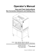
Manifold Valve
Pilot Gas Connection
Thermocouple Connection
Gas Line Input Connection
Gas Control Lever
(in Pilot position)
Flow Index Button
Gas Line Output
(connection to venturi)
1.4 Conversion and Adjustment Instructions
Before converting or adjusting the machine, it is imperative that the manual gas cock be
turned to the "off" position. The electrical power to the machines should also be turned off.
When converting from one type of gas to another, the main gas orifice (or injector), the
pilot burner orifice (or injector), and the primary air adjustment must be changed according
to the table on page 9. In addition, the spring in the pressure regulator must be changed so
that it can operate at higher pressures.
1.6 Verification for use with Natural Gas
The highest flame setting ("on" position on the manifold gas valves) for each of the pipe
burners can be confirmed by using the volumetric method in conjunction with the main gas
meter. From the "pilot" position, turn the Gas Control Lever clock-wise, towards "on", until
the lever goes no further.
To carry out this verification procedure, it is necessary to obtain the heating value (BTU/ft
3
)
of the local gas from the local gas company.
If the measured gas volume does not correspond to the values in the following table, the
first item which should be checked is the incoming (connected) gas pressure. If the
pressure is correct, it must be verified that the proper size gas orifices are in place.

Hickory Industries, Inc.
4900 Westside Avenue, North Bergen, New Jersey 07047
Tel: [201] 223-0050 Fax: [201] 223-0950
N/45 Series Manual12/00
Page 8 of 38
1.7.1 Volumetric Method to Verify the High Flame Setting, Mathematical
WARNING! No other gas equipment can be in operation during this procedure.
Calculation of flow rate E in ft
3
/hour
E = FP
H
i
E = Flow rate in ft
3
/minute
FP = High Flame Power setting in BTU/hr
H
i
= Heating value in BTU/ft
3
Thus, for natural gas:
E = 60,000 BTU/hr = 57.75 ft
3
/hr = 0.96 ft
3
/min.
1040 BTU/ft
3
E = 0.96 ft
3
/min.
Calculation of the natural gas needed in 1 hour by a 45WDG (3 burners) at full power:
57.75 * 3 = 173.25 ft
3
/hr = 2.89 ft
3
/min.
The time and the flow measurements should be taken at the gas (flow) meter with a
chronometer (stop watch).
To run the test, open the manual gas cock valve, start up the unit according to the start-up
instructions on page 24 and set the manifold valves to the high flame setting ("on" position).
Allow the unit to pre-heat (burn) for 10 to 15 minutes. Verify that the flow rate is calibrated
to the appropriate flow rate indicated in the table.
in ft
3
/hr
Gas Flow
per Burner (40,000 BTU)
BTU/ft³
Heating Value in
Gas
High Flame Setting
Natural
Propane
Butane
1040 57.75
1.7 Natural Gas Flow Table
2500
2500
24.00
24.00

Hickory Industries, Inc.
4900 Westside Avenue, North Bergen, New Jersey 07047
Tel: [201] 223-0050 Fax: [201] 223-0950
N/45 Series Manual12/00
Page 9 of 38
1.8 Orifice Diameters, Primary Air Intake Settings, and Pressure Regulators
Gas / Pressure Main Orifice
Pilot Orifice
Primary Air Intake
Ø in drill size Orifice Marking in inches
Natural / 5.5"
Propane / 11"
inches W.C.
Butane / 11"
5 holes @#55
3221
3221
3211
3/16"
3/16"
2 holes @#55
2 holes@#55
3/16 "
1/8 "
1/8 "

Hickory Industries, Inc.
4900 Westside Avenue, North Bergen, New Jersey 07047
Tel: [201] 223-0050 Fax: [201] 223-0950
N/45 Series Manual12/00
Page 10 of 38
Air Intake Adjustment
Lock Nut
Main Orifice
Venturi Tube
Venturi Assembly
1.9 Changing Gas Orifices
1.9.1 Changing the Main Gas Orifice
1. The venturi tubes and manifold valves are on the same side as the spit handles.
2. On each venturi, loosen the lock nuts (7/8" wrench) and then move the nut
and the air intake cap all the way to the top of the nipple.
3. With a 3/4" wrench, loosen the nipple so that it can be removed from the
venturi.
4. With the nipple/orifice assembly off, separate the main orifice from the
nipple with a pipe wrench or a pair of pliers.
Air Intake Cap
Nipple
Re-assemble all of the components with the new main orifice. Make sure that the proper air intake
adjustment is made for the new type of gas (according to the tables on page 9). The flames should be
blue in color, must be stable, and must not "lift off" the burner.

Hickory Industries, Inc.
4900 Westside Avenue, North Bergen, New Jersey 07047
Tel: [201] 223-0050 Fax: [201] 223-0950
N/45 Series Manual12/00
Page 11 of 38
1.9.2 Changing the Pilot Orifice
1. To reach the pilot burner, open the sliding glass doors, the sliding or hinged metal
door, remove all spits, as well as all ceramics.
2. Before removing, mark the position of the support bracket on the side wall.
3. Loosen the pilot burner assembly by removing the two screws which attach each
pilot burner (support bracket) to the main body of the machine.
4. With the assembly loose, carefully pull the entire assembly forward about 6".
5. Loosen the gas line connection to the pilot orifice with a 7/16" wrench. Carefully
separate the gas line from the pilot burner. From the pilot burner, carefully
remove the pilot orifice using a 1/2" wrench.
6. Reassemble the pilot burner using the new pilot orifice and place the support bracket
in its original position. The following pilot orifices are to be used with each type of
gas.
Pilot Orifice Marking
LPG 3221* Verbally confirm model 45 when ordering.
Natural Gas 3211*Verbally confirm model 45 when ordering.
Pilot Burner Assembly
Thermocouple
Pilot Flame
Openings
Pilot Orifice

Hickory Industries, Inc.
4900 Westside Avenue, North Bergen, New Jersey 07047
Tel: [201] 223-0050 Fax: [201] 223-0950
N/45 Series Manual12/00
Page 12 of 38
1.10 Checking the Connected Gas Pressure (Nominal Pressure)
Close the gas cock where the gas line is connected to the machine and attach a manometer
to the tap (allen screw) on the gas cock. With the manometer connected, open the gas
cock, ignite all burners, and set the manifold valves to "on" or maximum setting. Along with
all other gas appliances at the location in operation, measure the gas pressure.
This nominal pressure should be 5.5" W.C. for natural gas and 11" W.C. for LPG.
If the measured pressure falls below the range mentioned above, the installer should try to
find the cause of the problem and resolve it. A typical source of this problem is that the gas
line (pipe) diameter leading up to the unit is too small. If it is not possible to resolve the
problem, the local gas company or gas supplier should be contacted so that they can resolve
the problem.
If the nominal pressure is below 5.5 " W.C. for natural gas or below 11 " W.C. for LPG, the
unit should not be operated. These should be adjusted to the ideal settings using the pressure
regulating screw on the pressure regulator.
If the pressure is too high and can not be adjusted downward, check to see if the proper
adjusting spring is in place. If this is correct, the regulator membrane may have been
ruptured by excessive gas pressure and may have to be replaced. Do not operate the
rotisserie if the gas pressure is too low.
If the pressure is too low and can not be adjusted upward, also check the regulator. If this is
correct, verify the pressure coming out of the main gas meter or the diameter of the gas pipe
feeding gas to the unit. If the gas line is under-sized, the appropriate pressure may not be
reached. Do not operate the unit if the pressure falls below 5.5" W.C.
After the pressure has been set, close the gas cock once again, remove the manometer, seal
the pressure regulator, and then re-open the gas cock.
WARNING: After an installation, repairs, or maintenance, make sure that there are
no gas leaks anywhere in the gas lines or system.
1.11 Maintenance, response to technical problems, reasons for problems and solutions
Should a technical problem arise for any reason, shut off the machine and call for technical
service.

Hickory Industries, Inc.
4900 Westside Avenue, North Bergen, New Jersey 07047
Tel: [201] 223-0050 Fax: [201] 223-0950
N/45 Series Manual12/00
Page 13 of 38
Problem
Burners do
not ignite.
Pilot burner
ignites. Main
burner initially
ignites, but
then goes out.
Burners too
weak.
Burner
back-fires.
Pilot flame
does not stay
on.
Solution
a. Make sure that all gas valves are
open and that gas is reaching unit.
b. Remove and control the gas valve
at the connection (manual) or the
LPG pressure regulator. Contact
gas company or distributor.
a. Adjust thermocouple position.
b. Only the themocouple tip should be
enveloped by the pilot flame and
heated. The pilot flame must be
strong and blue in color.
c. Clean or adjust opening according
to table in page 9.
d. Tighten all thermocouple
connections.
e. Replace thermocouple (service co.).
a. Contact service or gas company.
b. Install correct orifices.
Adjust the primary air intake.
(contact service company)
a. Block off holes on the main burner
pipe directly below the pilot burner.
b. Replace thermocouple (service co.).
Cause
a. No gas flow.
b. Gas container too cold
especially with butane.
Water in gas freezes
in gas regulator.
a. Thermocouple tip is not
enveloped by pilot flame.
b. Thermocouple is not
heated enough by flame or
it is being heated along the
entire length too much.
c. Primary air intake blocked
or must be adjusted.
d. Thermocouple is loose at
one of the connections.
e. Defective thermocouple.
a. Gas pressure too low.
b. Wrong orifice size.
Too much primary air.
a. Flames on pipe burners
disrupting pilot flame.
b. Defective thermocouple.
A routine maintenance should be carried out at least once a year. Contact your local,
certified service company for maintenance.
1.12 Testing or checking for safety
After a conversion, a new installation, or after a repair, it is important that the unit be
tested to insure that it operates properly. This should include the following:
Test for gas leaks.
Check that the unit has enough clearance behind and to the sides.
Check that enough primary and secondary air is available (strong blue flames).
Check for potentially flammable objects or potential flammability problems.
Check the gas distribution systems.
Check for proper ventilation and exhaust.
Check for proper room ventilation.

Hickory Industries, Inc.
4900 Westside Avenue, North Bergen, New Jersey 07047
Tel: [201] 223-0050 Fax: [201] 223-0950
N/45 Series Manual12/00
Page 14 of 38
When first installing, after repairing, or after cleaning the units, it is important to make
sure that all components are properly in place.
a. There should be a total of 9, evenly spaced ceramic bricks sitting above each main
pipe burner.
b. The ceramics must be sitting directly on the burners. These ceramic
bricks should also be placed so that they fit between the ceramic support rods.
c. The burner pipes should not have any holes (flames) directly below the pilot
burner assembly. If holes (flames) are present, they will overheat the thermocouple or
blow out the pilot flame, preventing the main burner from staying lit.
1.15 Electrical Diagram - All Models
1.14 Description of the Electrical Connection
The electrical connections are to be made in accordance to local and national codes.
All gas machines operate with 120 Volt, single phase, 60 Hz. A NEMA 5-15P plug
is supplied with the units.
All pertinent electrical information can be taken from the electrical diagram.
L N
L
M

Hickory Industries, Inc.
4900 Westside Avenue, North Bergen, New Jersey 07047
Tel: [201] 223-0050 Fax: [201] 223-0950
N/45 Series Manual12/00
Page 15 of 38
1.16 Parts List for N /4 5WDG
Item Qty. Description Material Length Size Manufacturer
113 39 Ceramic Radiants (Single Face) Ceramic Hickory
1 Accordian Door (Option) SS Hickory
120 2 Drip Pan45 SS Hickory
121 2 Drip Pan Plug Brass Hickory
122 2 Drip Pan Receptacle Brass Hickory
131 2 Fiber Motor Worm Gear Fiber Hickory
409T 1 Glass Track, Top SS Hickory
409B 1 Glass Track, Bottom SS Hickory
410 2 Glass Trolley 45 Alum. Hickory
2 Handle 45 Alum. Hickory
150 2 Lamp Par, 120 V Hickory
155 2 Motor, 1/3 HP - 120V Hickory
157 2 Motor Worm Steel SS Hickory
158 33 Oil Lite Bushing Brass Hickory
159 6 Pillow Block Bearing 5/8" SS Hickory
414 2 Reflector Panel 45WDG Curved SS Hickory
415 3 Reflector Panel 45 WDG Flat SS Hickory
182 1 Shaft 5/8" SS Hickory
184 22 Shaft Worm Nylon Hickory
420 2 Spit Plate, N/45 Exterior SS Hickory
421 1 Spit Plate, N /45 Center SS Hickory
414 1 Top Reflector Single SS Hickory
227 3 Venturi Cap Iron Hickory
229 3 Venturi Lock Nut 3/8" ID, 3/4" OD Iron Hickory
231 3 Venturi Nipple Steel Hickory
233 3 Venturi Threading Tube, Brass Steel Hickory
234 3 Venturi Tube Iron Hickory
232 3 Main Orifice, Nat. Gas Brass Hickory
162 3 Pilot Burner (includes pilot orifice) Steel Hickory
163 3 Pilot Gas Line Alum. Hickory
164 3 Pilot Thermocouple Copper Hickory
138 3 Gas Pipe Burner Steel 1 - 1/2" Hickory
175 3 Retainer Rod 45 for Ceramics SS Hickory
152 2 Lamp Socket Ceramic Hickory
214 3 Switch, 1-Pole Hickory
110 2 Caster w/ brake Nylon Hickory
111 2 Caster w/o brake Nylon Hickory

Hickory Industries, Inc.
4900 Westside Avenue, North Bergen, New Jersey 07047
Tel: [201] 223-0050 Fax: [201] 223-0950
N/45 Series Manual12/00
Page 16 of 38
1.16 Parts List for N / 45WDG (Contd.)
Item Qty. Description Material Length Size Manufacturer
417 9 Spit Regular Complete (with screws) SS Hickory
179 2/spit Roll Pin 1/8" Stainless SS Hickory
190 9 Spit Regular, without collar SS Hickory
191 9 Spit Collar SS Hickory
192 9 Spit Gear Nylon Hickory
419 9 Spit Handle, 6" Short Nylon Hickory
185 4/Spit Skewer Double SS Hickory
186 2/Spit Skewer Single SS Hickory
219 6/Acc. Thumb Screw SS Hickory
408 2 Tempered Glass 30"x33 3/4" Tempered Glass Hickory
407 2 Glass Frame 45 SS Hickory
165 1 Pressure Regulator 3/4" Alum. 3/4" Maxitrol
7A 1 Pipe Steel 3.5" 3/4" Hickory
135 1 Gas Cock Valve Steel 3/4"
7B 1 Pipe Steel 6" 3/4" Hickory
7C 3 T-Connector Steel 3/4" Hickory
7D 6 Nipple (Adapter 3/4" to 3/8") Steel 1.7" Hickory
132 3 Flexible Pipe SS 4.25" 3/8" Dormont
180 3 Manifold Gas Valve SS 3/8" Baso
7E 3 Nipple Steel 1.5" 3/8" Hickory
226 3 Venturi Assembly Iron 3/8" - 1-1/2" Hickory
228 3 Venturi Elbow, 90º Iron 1-1/2" Hickory
7F 1 Pipe Steel 14.5" 3/4" Hickory
7G 1 Pipe Steel 16" 3/4" Hickory
7H 1 Pipe Cap (threaded) Steel 3/4" Hickory
The following parts are not shown in the diagrams:
123 1 Electrical Grounding Cap Hickory
Electrical Wire Janor Wire
1 Connection Cable TIP Products
104 1 Contact Section 242 (terminal) Buchanan
105 1 Contact Section 250 (end-piece) Buchanan
*All components are inventories and sold through Hickory Industries and their distributors and dealers.

Hickory Industries, Inc.
4900 Westside Avenue, North Bergen, New Jersey 07047
Tel: [201] 223-0050 Fax: [201] 223-0950
N/45 Series Manual12/00
Page 17 of 38

Hickory Industries, Inc.
4900 Westside Avenue, North Bergen, New Jersey 07047
Tel: [201] 223-0050 Fax: [201] 223-0950
N/45 Series Manual12/00
Page 18 of 38

Hickory Industries, Inc.
4900 Westside Avenue, North Bergen, New Jersey 07047
Tel: [201] 223-0050 Fax: [201] 223-0950
N/45 Series Manual12/00
Page 19 of 38

Hickory Industries, Inc.
4900 Westside Avenue, North Bergen, New Jersey 07047
Tel: [201] 223-0050 Fax: [201] 223-0950
N/45 Series Manual12/00
Page 20 of 38
II. Operating Instructions
1.0 Start Up
a. Switch the exhaust hood to on.
b. Open the gas cock at the rear of the machine.
c. Turn the knob on the manifold valve to the "pilot" position.
d. While pressing the "flow index" button down, place a match, or other type of
ignition method, to the pilot burner until it is lit. Keep the knob pressed down
for at least 40- 60 seconds so that the thermocouple tip warms up and the pilot
flame remains lit.
e. Release the knob. The pilot flame should stay on.
f. Repeat the procedure for the other burners.
g. Turn the manifold valve knob to the desired setting ("on" must be lined up
with the "flow index" button for high flame or maximum heat). The pipe
burner should now light up.
h. Allow the unit to pre-heat for about 15 minutes.
i. When ready to load the spits with product, turn the light and the motor
switches to the on position.
2.0 Shut Down
a. Turn the manifold valve knobs to the "off" position if all flames are to be
shut off. If the pilot light is to remain lit and only the pipe burners are to be
shut off, turn the manifold valve knobs to the "pilot" position. Note that to
turn the knobs to the "off" position, one must pull out on the locking
mechanism on the knobs and then turn the valve to the off position.
b. After all of the loaded spits have been removed, turn the motor and lights off.
c. Close the gas cock at the rear of the machine if the pilot flames are also shut
off.
d. Turn off the exhaust hood.
WARNING! Do not clean the machine or glass while these are hot! Everything
should be cooled down before cleaning.
/