Page is loading ...

1
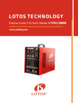
LOTOS TIG200
TIG/Stick Welder

2
TABLE OF CONTENTS
SAFETY...………………………………………………………………………..4
SPECIFICATIONS…….………………………………………………………..9
General Description…………………………………………………………..9
What’s Included………………………………………………………………9
Power Supply Rating…..……………………………………………………..11
What You Need to Operate This Machine…………………………………...12
Control Panel Information……………………………………………………12
Machine Rear ………………………………………………………………..13
Front Control Panel ………………………………………………………….13
INSTALLATION………………………………………………………………..14
Before Installation……………………………………………………………14
Setup Instructions…………………………………………………………….15
Installation Diagrams………………………………………………………...16
TROUBLESHOOTING………………………………………………………...17
How to Use the Troubleshooting Guide……………………………………...17
Common Problems…………………………………………………………...17
Troubleshooting Welding…………………………………………………….18
OTHER ACCESSORIES……………………………………………………….20

3
TIG200 TIG/STICK WELDER
Save This Manual
You will need the manual for safety warnings and precautions, assembly
instructions, operating and maintenance procedures, parts list and diagram.
Keep your invoice with this manual. Write invoice number and date of
purchase on the inside of the manual. Keep the manual and invoice in a safe
and dry place for future
Operation Manual
Carefully read the operation manual prior to using, installing and
maintaining the electric welding machine for the purpose of preventing
damages such as fire, electric shock and etc from occurring. Please keep the
manual for the reference in the future.

4
SAFETY WARNINGS AND PRECAUTIONS
PLEASE READ AND UNDERSTAND THE FOLLOWING SAFETY HIGHLIGHTS.
BE SURE THAT ALL INSTALLATION, OPERATION, MAINTENANCE AND
REPAIR PROCEDURES ARE PERFORMED ONLY BY QUALIFIED INDIVIDUALS. ARC
AND TIG WELDING CAN BE HAZARDOUS. PROTECT YOURSELF AND OTHERS FROM
POSSIBLE SERIOUS INJURY OR DEATH. KEEP CHILDREN AWAY. PACEMAKER
WEARERS SHOULD CONSULT WITH THEIR DOCTOR BEFORE OPERATING.
WHEN USING THE WELDER, ALL BASIC SAFETY PRECAUTIONS SHOULD ALWAYS BE
FOLLOWED TO REDUCE THE RISK OF PERSONAL INJURY AND DAMAGE TO
EQUIPMENT.
DRY WORKING PLACE. DO NOT WELD IN PLACES WITH HIGH HUMIDITY.
FOR THE POWER EXTENSION CORD, PLEASE MAKE SURE THE WIRE GAUGE IS MORE
THAN 11 GAUGE AT 220VAC AND 13 GAUGE AT 110VAC. USING A NON-METALLIC
CHAIR PLACED ON A RUBBER MAT WHILE WELDING IS RECOMMENDED. USE 20 AMPS
CIRCUIT BREAKER FOR 110VAC AND 30 AMPS CIRCUIT BREAKER FOR 220VAC. DO NOT
USE TRIPLE PHASE, INSTEAD USE SINGLE PHASE POWER.
READ ALL INSTRUCTIONS BEFORE USING THIS WELDER.
Keep work area clean. Cluttered areas invite injuries.
Observe work area conditions. Do not use machines or power tools in damp or wet locations.
Do not expose to rain. Keep work area well-lighted. Do not use electrically powered tools in the
presence of flammable gases or liquids.
Keep children away. Children must be never be allowed in the work area. Do not let them
handle machines, tools or extension cords.
Store idol equipment. When not in use, tools must be stored in a dry location to inhibit rust.
Always lock up tools and keep them out of the reach of children.
Do not force tool. It will do the job better and safer at the rate for which it was intended. Do not
use inappropriate attachments in an attempt to exceed the tool capacity.
Use the right tool for the job. Do not attempt to force a small tool or attachment to do the work
of a larger industrial tool. There are certain applications for which this welder was designed. Do not
modify this welder and do not use this welder for any other purposes for which it was not intended.
Dress properly. Do not wear loose clothing or jewelry as they can be caught in moving parts.
Protective, flame retardant, electrically non-conductive clothing and non-skid footwear are
recommended when working. Wear restrictive hair covering to contain long hair.
Use eye and ear protection. Always wear ANSI approved, arc shaded, impact safety face shield
(welding helmet). Always use a full-face shield when welding. Always wear ANSI approved eyewear
under face shield and while in the workplace. Wear a NIOSH approved dust mask or respirator when
working around metal, chemical dusts, fumes and mists.
Do not over reach. Keep proper footing and balance at all times. Do not reach over or across
running machines.
Maintain tools with care. Keep tools sharp and clean for better and safer performance. Follow

5
instructions for lubricating and changing accessories. Inspect tool cords periodically and, if damaged,
have them repaired by an authorized technician. The handl;es must be kept clean, dry, and free from
oil and grase at all times.
Disconnect power. Unplug tool when not in use.
Remove adjusting keys and wrenches. Check that keys and adjustment wrenches are removed
from the welder and work area before plugging in.
Avoid starting unintentionally. Be sure the switch is in the off position when not in use and
before plugging in. Do not carry any tool with your finger on the trigger, whether it is plugged in or
not.
Stay alert. Watch what you are doing. Use common sense. Do not operate any tool when tired.
Check for damaged parts. Before using any tool, any part that appears damaged should be
carefully checked to determine that it would operate properly and perform its intended function.
Check for alignment and binding of moving parts; any broken parts or mounting fixtures; and any
other condition that may affect proper operation. Any part that is damaged should be properly repaired
or replaced by a qualified technician. Do not use the tool if any switch does not turn on and off
properly.
Guard against electric shock. Prevent body contact with grounded surfaces such as pipes,
radiators, ranges, and refrigerator enclosures.
Replacement parts and accessories. When servicing, use only identical replacement parts. Use
of any other parts will void warranty. Only use accessories intended for use with this welder.
Approved accessories are available from www.uwelding.com.
Do not operate tool if under the influence of alcohol or drugs. Read warning labels on
prescriptions to determine if your judgment or reflexes are impaired while taking drugs. If there is any
doubt, do not operate the welder.
Maintenance. For your safety, service and maintenance should be performed regularly by a
qualified technician.
Use proper size and type extension cord. If an extension cord is required, it must be of the
proper size and type to supply the correct current to the welder without heating up. Otherwise, the
extension cord could melt and catch fire, or cause electrical damage to the welder. This welder
requires use of an extension cord of 20 amps minimum capability up to 30 feet, with a wire size rated
at 12 AWG. Longer extension cords require larger size wire. If you are using the welder outdoors, use
an extension cord rated for outdoor use, signified by “WA” on the jacket. Performance of this welder
may vary depending on condition in local line voltage. Extension cord usage may also affect welder
performance.
The warnings, cautions and instructions discussed in this instruction manual cannot cover all
possible conditions and situations that may occur. It must be understood, by the operator, that
common sense and caution are factors, which cannot be built into this product, but must be
supplied by the operator.
ARC WELDER SAFETY WARNINGS AND PRECAUTIONS
Warning: This product, when used for welding and similar applications, produces chemicals to
cause cancer and birth defects (or other reproductive harm).

6
ELECTROMAGNETIC FIELDS may be dangerous
The EMF field that is generated during arc welding may interfere with
various electrical and electronic devices such as cardiac pacemakers.
Anyone using such devices should consult with their physician prior to
performing any electric welding operations.
Exposure to EMF fields while welding may have other health effects, which
are not known.
ELECTRIC SHOCK can be fatal
Read all precautions described in this manual to reduce the possibility of
electric shock.
Improper use of an electric welder can lead to electric shock, injury, and
death!
The power switch should be in the OFF (“0”) position when installing
the work cable and gun and while plugging in the power cord.
The machine must be securely grounded. Ground the work metal to be welded to a good
electrical (earth) ground. Always attach the ground clamp to the piece to be welded and as
close to the weld area as possible. This will give the least resistance and best weld.
Maintain the welding torch, work clamp, power cable and welding machine in good, safe
operating condition. Replace damaged insulation.
Always wear dry, protective clothing and leather welding gloves and insulated footwear. You
have to the wear the welding gloves and auto-darkening welding helmet to protect your hands
and eyes from the harmful arc. Please check www.uwelding.com for proper tig welding
helmet.
Always operate the welder in a clean, dry, well-ventilated area. Do not operate the welder in
humid, wet, rainy or poorly ventilated areas.
Do NOT touch the torch head when the button is depressed. It will cause a serious shock and
burn.
The electrode and work (or ground) circuits are electrically “hot” when the welder is on. Do
not touch these “hot” parts with your bare skin or clothing.
Due to high frequency, keep all cell phone, cameras, and other electronic devices at least 7
feet away from the machine and torch.

7
ARC RAYS can be dangerous
Use a shield with the proper filter (a minimum of #11) to protect your eyes
from sparks and the rays of the arc when welding or observing open arc
welding.
Use suitable clothing made from durable flame-resistant material to protect
your skin and that of your helpers from the arc rays.
Protect other nearby personnel with suitable, non-flammable screening and/or warn them not to
watch the arc nor expose themselves to the arc rays or to hot spatter or metal.
HOT METAL will burn
Electric welding operations cause sparks and heats metal to temperatures
that will cause severe burns!
Use protective gloves and clothing when performing any welding
operations.
Always wear long pants, long-sleeved shirts and leather welding gloves.
Make sure that all persons in the welding area are protected from heat, sparks and ultraviolet rays.
Use additional face shields and flame-resistant barriers as needed.
Never touch a work piece until it has completely cooled.
FUMES AND WELDING GASES can be dangerous
Do not breathe fumes that are produced by the welding operation. These
fumes are dangerous
Shielding gases used for welding can displace air and cause injury or death.
Always work in a properly ventilated area.
Read and understand the manufacturer’s instructions for this equipment
and the consumables to be used, including the material safety data sheet (MSDS) and follow your
employer’s safety practices. MSDS forms are available from your welding distributor or from the
manufacturer.
WELDING SPARKS can cause a fire or an explosion
Remove fire hazards from the cutting area. If this is not possible, cover them
to prevent the welding sparks from starting a fire. Remember that welding sparks
and hot materials from cutting can easily go through small cracks and openings to
adjacent areas. Avoid cutting near hydraulic lines. Have a fire extinguisher readily
available. Do not operate the electric arc welder in areas where flammable or
explosive vapors are present.
Where compressed gases are to be used at the job site, special precautions should be used to
prevent hazardous situations.
Do not heat, cut or weld tanks, drums or containers until the proper steps have been taken to
insure that such procedures will not cause flammable or toxic vapors from substances inside.
They can cause an explosion even though they have been “cleaned”.
Always keep a fire extinguisher nearby while welding.
Use welding blankets to protect painted surfaces, dashboards, engines, etc.
Please make sure there are no combustible items around your welding are

8
CYLINDER may explode if damaged
Use only compressed gas cylinders containing the correct shielding gas for the
process used and properly operating regulators designed for the gas and pressure
used. All hoses, fittings, etc. should be suitable for the application and maintained
in good condition.
Always keep cylinders in an upright position securely chained to an
undercarriage or fixed support.
Cylinders should be located:
Away from areas where they may be struck or subjected to physical damage.
A safe distance from arc welding or cutting operations and any other source of heat,
sparks, or flame.
Never allow any electrically “hot” parts to touch a cylinder.
Keep your head and face away from the cylinder valve outlet when opening the cylinder
valve.
Valve protection caps should always be in place and hand tight except when the cylinder is in
use or connected for use.
ELECTRICALLY POWERED EQUIPMENT can be dangerous
Turn off input power using the disconnect switch at the fuse box before
working on the equipment.
Install equipment in accordance with the local codes and the manufacturer’s
recommendations.
Ground the equipment in accordance with the manufacturer’s
recommendations.
MOVING PARTS can cause injury
Keep away from moving parts such as fans.
Keep all doors, panels, covers, and guards closed and securely in place.
Please read this Operation Manual carefully and thoroughly before attempting to
operate this machine. Keep this manual handy for quick reference. Pay close
attention to the safety instructions provided for your own protection.

9
SPECIFICATIONS
GENERAL DESCRIPTION
This compact, dual-voltage, versatile TIG200 offers user a simple array of controls to accurately set the welder to
perform under a wide variety of situations. Its square-wave inverter enables accurate welding of fine aluminum. It
allows user to easily switch from 220v to 110v with the included plug adapter, and produces AC/DC 200 amps for TIG
and STICK welding. It is perfect for a professional or a weekend enthusiast who is looking to get industrial quality
features in a durable and affordable welder.
200-amp AC/DC square-wave inverter TIG/Stick(MMA) Welder
Automatic dual-voltage/dual-frequency (110/220-volt 50-60Hz)
HF start hand torch control and precise foot pedal welding heat control
Suitable for welding stainless steel, mild steel, aluminum, and other metal materials.
WHAT’S INCLUDED
Power Supply
TIG Torch
Stick Electrode Holder
Ground Clamp and Cable
Pigtail Adapter Type 2
Argon Hose
Argon Regulator
Foot Pedal
Hand-Held Shield,
Wire Brush, Etc.
GROUND CABLE & CLAMP
POWER SUPPLY
STICK ELECTRODE
HOLDER
TIG TORCH
PIGTAIL ADAPTER
TYPE 2
POWER SUPPLY

10
HAND-HELD SHIELD,
WIRE BRUSH, ETC.
ARGON REGULATOR
ARGON HOSE
FOOT PEDAL

11
POWER SUPPLY RATINGS
TIG200
General
Specification
Output Power
AC/DC
Input Voltages
110/220V ± 15%, 1-PH, 50/60Hz
Input Current
15A @110V, 30A @220V
Power Factor
0.73
Power Efficiency
80%
Duty cycle
1
@ 40°C (104°F)
60% @150A, 110V
100% @110A, 110V
60% @190A, 220V
100% @150A, 220V
Dimensions with handle
28” (711mm) L
13” (330mm) W
17” (432mm) H
Weight w/ 8'11’’ (2.7 m) torch
58lbs (26.3kg)
Gas Supply
Clean, dry, oil-free argon
Recommended gas inlet flow rate /
pressure
3.6scfm @65psi
Input power cable length
6’ (1.8m)
Material
2
Mild Steel
Welding Capacity: ¼” (6mm)
Stainless Steel
Aluminum
Other Metals
Warranty
New Unit
1-Year Warranty
Refurbished Unit
60-Day Warranty
1
Duty Cycle is percentage of 10 minutes that unit can weld at rated load without overheating.
2
Production weld thickness are the results of Lotos’ laboratory testing. Production speeds are
approximately 80% of maximum. For optimum weld quality, welding speeds may vary based on different
welding applications.

12
WHAT YOU NEED TO OPERATE THIS MACHINE?
A properly grounded 110-120 VAC 50/60 hz. Circuit or a 220-240 VAC 50/60 hz. 30-50 amp
Circuit.
Remember: Machine must be grounded to work properly and safely!
A clean and well-ventilated working place
Heavy Duty Welding Gloves
An Auto-Darkening Welding Mask to provide eye protection
A compressed gas cylinder containing pure Argon
Stainless steel wire welding brushes for each material to be welded
A stone grinding wheel or a Tungsten Sharpener to sharpen the tungsten electrode
Control Panel Information
1. Power switch 1 is located on the back of the machine.
2. Downslope adjustment knob 2: In order to reduce the current gradually before the welding
stops.
a. This knob is to adjust the current descending time.
b. Note: If you are using the “foot pedal” control; you should turn this knob
counter-clockwise to “0”.
3. Post-flow time adjustment (knob 3): To prevent the work piece from becoming oxidized, let
the argon flow for few seconds after stopping the welding arc. This knob is for adjusting the
post-flow time.
4. Foot pedal switch 4: When the switch is on the “OFF” position, the current is adjusted by
using the Current adjustment knob 5; when it is on the “PEDAL” position, the current is
adjusted dynamically by foot pedal.
5. Current adjustment knob 5. Note: it only works when switch 4 (pedal/off) is on the “OFF”
position. If switch 4 is set on the “PEDAL” mode, the current would be fully controlled by
using the foot pedal instead.
6. Pulse duty knob 6: During AC aluminum Tig welding, Note: For an increased welding
voltage of more than 150A, use pulse duty below 30% (or less than -1). For medium voltage
(from 100A to 150A), use pulse 50% (0 on knob); For voltages less than 100A, use pulse duty
more than 50% (+1 to +5).
7. Pre-flow time adjustment (knob 7): For better welding results, argon gas should come earlier
than the current. This knob is to adjust the time between argon start and electric arc start.
8. Stick welding/Tig Welding Switch 8. For Tig welding, please switch to “Tig Mode”, For Stick
Welding, please switch to “MMA mode”.
9. AC/DC Switch 9: For Aluminum welding, please switch to AC, for non-aluminum welding,
please switch to DC.
Overheat protection indicator (OC light): This is to protect the machine if it overheats. If the light is
on, please stop the machine for 4 to 10 minutes before turning it on again.

13
MACHINE REAR
The unit is connected to the supply even if
the Power Switch is on the “OFF” position,
and therefore there are electrically live parts
inside the power source. Carefully follow the
instructions given in this manual.
REAR COMPONENTS
1
Power Switch
FRONT CONTROL PANEL
FRONT CONTROL PANEL
2
Down Slope Time Adjustment
3
Post-flow Time Adjustment
4
Foot Pedal Switch
5
Voltage Adjustment
6
Clearance Effect Pulse Width Adjustment
7
Opening for Ground Cable
8
Stick Welding/TIG Welding Switch
9
AC/DC Switch
10
Tig Torch Gas Connector
11
Stick Welding Cable Connector
12
Tig Torch Electrical Connector
13
Foot Pedal Connector
14
Ground Cable Connector

14
INSTALLATION
PLEASE READ ENTIRE INSTALLATION SECTION BEFORE STARTING
INSTALLATION. BE SURE THAT ONLY QUALIFIED PERSONNEL SHOULD
PERFORM THIS INSTALLATION.
__________________________________________________________________
BEFORE INSTALLATION
ELECTRIC SHOCK can be fatal
Turn the input power OFF and unplug the machine from the receptacle before working
on this equipment. Allow machine to sit for 5 minutes minimum to allow the power
capacitors to discharge before working inside this equipment.
Insulate yourself from the work and ground.
Always wear dry insulating gloves.
SELECT SUITABLE LOCATION
The Inverter will operate in harsh environments. Even so, it is important that simple preventative
measures are followed in order to assure long life and reliable operation.
The machine must be located where there is free circulation of clean air such that air movement
in the back and out the front will not be restricted.
Dirt and dust that can be drawn into the machine should be kept to a minimum. Failure to
observe these precautions can result in excessive operating temperatures and nuisance
shutdown.
STACKING
TIG200 cannot be stacked.
TILTING
Place the machine directly on a secure, level surface. The machine may topple over if this
procedure is not followed.
ENVIRONMENTAL AREA
Keep the machine dry. Do not place it on wet ground or in puddles. Avoid rainwater. Operating in
rain is not allowed.

15
SETUP INSTRUCTIONS
ELECTRIC SHOCK can be fatal
Have a qualified electrician install and service this equipment.
Turn the input power OFF and unplug the machine from the receptacle before working
on this equipment.
Allow machine to sit for 5 minutes minimum to allow the power capacitors to discharge
before working inside this equipment.
Do not touch electrically hot parts.
Machine must be plugged into a receptacle that is grounded according to the National
Electrical Code and local codes.
Do not remove or defeat the purpose of the power cord ground pin.
1. The machine will automatically detect the power of 110VAC to 220VAC. For 110VAC,
please attach the 220VAC to the 110VAC adapter cord.
2. Connect your Argon Tank to Argon Regulator and connect your Argon Regulator to the gas
inlet on the back of the machine (rear panel). Set the gas flow from 12 to 21 scfh.
3. For Tig welding, set Switch 8 to “TIG” mode, connect your Tig torch to Connectors 10 and
12.
4. If you are using the foot pedal, then connect your pedal to Connector 13 and set Switch 4 to
“Pedal” mode. If you are not using the foot pedal, then set Switch 4 to “OFF” mode.
5. Connect your Ground Cable to Connector 14 and attach your Ground Clamp to your work
piece.
6. For non-aluminum welding, please set Knob 9 to the “DC” mode. For aluminum welding, set
Knob 9 to the “AC” mode.
7. For Stick/MMA welding, you do NOT need gas supply. Just hook your Stick Electrode
Holder cable to Connector 11 and hook the Ground Cable to connector 14 and attach your
Ground Clamp to the work piece. Set Switch 8 to “MMA” mode, Set the machine to “AC”
mode for aluminum stick welding and “DC” for non-aluminum stick welding.
Note: For output amperage, “more is not always better” as too high of an current
setting will burn the tungsten electrodes and welded material.
8. For Clearance Effect Knob 6, it is for shifting the heat either to the work piece or to the
Tungsten Electrode. Turning the knob toward “-“ will induce more heat to the material you
are welding. While turning the knob toward “+” will induce more heat to the torch and gives
less penetration to the work piece. So turn the knob towards “-“ if the welding voltage is more
than 150A and turn the knob towards “+” if the welding voltage is less than 100A.
9. For Tungsten Electrodes, please refer to www.uwelding.com for proper equipment for
different types of welding.
10. For non-aluminum Tig welding, please sharpen the tungsten tip. For aluminum tig welding,
please hold the torch 1/8” from the aluminum surface. Depress and hold foot pedal at the ½
postion for 4 seconds then go to ¾ to full as required to form a ball on the tungsten. This is
necessary to achieve a smoother and more high quality aluminum Tig welding.

16
INSTALLATION DIAGRAMS

17
TROUBLESHOOTING
PLEASE READ AND UNDERSTAND THIS ENTIRE SECTION. SERVICE AND
REPAIR SHOULD ONLY BE PERFORMED BY TRAINED PERSONNEL FOR
YOUR SAFE, PLEASE OBSERVE ALL SAFETY INFORMATION
THROUGHOUT THIS MANUAL.
HOW TO USE THE TROUBLESHOOTING GUIDE
This Troubleshooting Guide is provided to help you locate and repair possible machine
malfunctions. Simply follow the three-step procedure listed below.
Step 1. LOCATE PROBLEM (SYMPTOM).
Look under the column labeled “PROBLEM (SYMPTOMS)”. This column describes possible
symptoms that the machine may exhibit. Find the listing that best describes the symptom that the
machine is exhibiting.
Step 2. POSSIBLE CAUSE.
The second column labeled “POSSIBLE CAUSE” lists the obvious external possibilities that may
contribute to the machine symptom.
Step 3. RECOMMENDED ACTION
This column provides a course of action for the Possible Cause.
If you do not understand or are unable to perform the Recommended Course of Action safely,
contact your dealer.
COMMON PROBLEMS
BLACK WELDING SPOT
It might have been caused by an over-oxidized welding spot. Please make sure there is
sufficient gas flow. Make sure that the valve of Argon Tank has been opened with enough gas
pressure. If the pressure is lower than 0.5MPa, then it is necessary to refill the cylinder.
ARC CANNOT BE STARTED OR DISCONTINUOUS ARC
1. Make sure the Tungsten Electrode is the right type for your welding material.
2. Tungsten tip should be sharpened for non-aluminum welding and should be formed to a ball
shape for aluminum welding.
ELECTRIC SHOCK can be fatal
Service and Repair should only be performed by a Trained Personnel. Have a qualified
electrician install and service this equipment.

18
OUTPUT CURRENT CANNOT REACH RATED VALUE
Deviation of power voltage from the rated value will lead to unconformity of output current
value with the set value. When power voltage is lower than the rated value, maximum
output current of the welder may also be lower than the rated value.
TUNGSTEN TIP GETS BURNT TOO FAST
Reduce the heat of the tungsten tip by twisting knob 6 towards “-“.
TROUBLESHOOTING WELDING
PROBLEMS
RECOMMENDED ACTION
Weak Penetration
(For aluminum Tig welding)
Increase the welding heat, use 220VAC and use higher
output voltage
Twist knob 6 towards “-“ to transfer more heat to the
work piece
Weak Penetration
(For aluminum Tig welding)
Increase the welding heat, use 220VAC and use higher
output voltage
Tungsten Contaminated
Keep Tungsten 1/8 to ¼ inches from the base metal.
Re-sharpen the Tungsten if the tip is worn.
Poor Welding Appearance
The angle between the filler metal and the torch must be
less than 90 degrees.
Crater at the End of the Weld
Bead
Keep the torch on the base metal while the post flow
shielding gas flows to protect the metal and tungsten.
Reduce current with pedal and add more filler at the end
of the weld.
Weld Bead is Cracking
Reduce the heat more times between passes.
Preheat the base metal and reduce the filler wire size.
Material is Warping
Clamp the work piece tightly.
Add more tack welds until rigidity and stiffness is
developed.
To reduce heat by spreading the welding out around the
area. This can be done by using Stitch Welding techniques
and by alternating sides, taking your time, allowing the
pieces to cool between passes.
Melting Tungsten
Make sure there is no gas leaking, adjust the gas flow,
shift more negative on the knob 6.
Increase the Tungsten diameter. Increase the Post Flow.
For Tig welding, please use 100% pure argon.
Contamination in Weld Bead
Clean the base metal to make sure to remove any oil,
coating or debris.
Remove tungsten from torch and re-sharpen the tungsten.

19
Arc Cannot Start
Make sure the machine is securely grounded.
Use the right type of Tungsten.
Make sure there is enough gas flow.
Make sure the settings is on “DC” for non-aluminum and
“AC” for aluminum.
Make sure the setting for the foot pedal switch is correct.
Arc Runs Around and Heat
Cannot be Concentrated
in a Specific Area
Check Tungsten type and tip size.
Adjust the rate of gas flow.
Make sure the Tungsten is not contaminated.
Make sure the Tungsten is held 1/8 to ¼ inches off the
work piece.
Make sure the machine is securely grounded.
Make sure the metal piece is not contaminated.
Shift Knob 6 towards “-“ negative.
/

