Page is loading ...

13006-90440-MAN (Rev. 1) © Diversified Technical Systems, Inc. All Rights Reserved.
SLICE6 AIR DAS
User’s Manual
February 2020

SLICE6 AIR DAS User’s Manual February 2020
support.dtsweb.com ii 13006-90440-MAN (Rev. 1)
Table of Contents
DTS Support ....................................................................................................................... 4
Introducing the SLICE6 AIR DAS ...................................................................................... 5
Sensor Interface ................................................................................................................. 6
Supported Sensor Types ................................................................................................. 6
Input Range ..................................................................................................................... 6
Excitation Sources ........................................................................................................... 7
Bridge Completion ........................................................................................................... 7
Hardware Filters ............................................................................................................... 7
Offset Compensation ....................................................................................................... 7
Electronic Identification (EID) ........................................................................................... 7
Shunt Emulation ............................................................................................................... 7
System Connector.............................................................................................................. 8
Communication Method ................................................................................................... 8
Timing Synchronization .................................................................................................... 8
Power Management ......................................................................................................... 8
Power-up and Power-down Procedures ...................................................................... 9
LEDs .................................................................................................................................... 9
Status (STS) LED ............................................................................................................ 9
Power (PWR) LED ......................................................................................................... 10
Data Memory Size............................................................................................................. 11
Sampling Rates .............................................................................................................. 11
Circular Buffer Limitations .......................................................................................... 11
Basic Care and Handling ................................................................................................. 12
Shock Rating .................................................................................................................. 12
Mounting Considerations ........................................................................................... 12
Thermal Considerations ................................................................................................. 12
Environmental Rating ..................................................................................................... 13
Software ............................................................................................................................ 14
Data Collection Concepts............................................................................................... 14
Data Collection Modes ................................................................................................... 14

SLICE6 AIR DAS User’s Manual February 2020
support.dtsweb.com iii 13006-90440-MAN (Rev. 1)
Circular Buffer Mode .................................................................................................. 14
Recorder Mode .......................................................................................................... 14
Hybrid Recorder Mode ............................................................................................... 15
Continuous Recorder Mode ....................................................................................... 15
Data Streaming .............................................................................................................. 15
Start Record and Event Initiation ................................................................................... 15
Appendix A: Hardware Specifications ........................................................................... 17
Mechanical Specifications, Connector Information and Pin Assignments ...................... 17
Ethernet Chaining .......................................................................................................... 18
Accessories/Support Equipment .................................................................................... 18
Appendix B: Hardware Configuration Specifications .................................................. 19
Using the SLICE Network Configuration Utility .............................................................. 19
Appendix C: Sensor Interface Wiring Diagrams ........................................................... 22
Appendix D: Declaration of CE Conformity .................................................................. 30

SLICE6 AIR DAS User’s Manual February 2020
support.dtsweb.com 4 13006-90440-MAN (Rev. 1)
DTS Support
SLICE systems are designed to be reliable and simple to operate. Should you need
assistance, DTS has support engineers worldwide with extensive product knowledge and
crash test experience to help via telephone, e-mail or on-site visits.
The best way to contact a DTS support engineer is to submit a request through the DTS Help
Center web portal (support.dtsweb.com). You must be registered
(support.dtsweb.com/registration) to submit a request (https://support.dtsweb.com/hc/en-
us/requests/new). Registration also enables access to additional self-help resources and
non-public support information.
This manual supports the following products:
13006-90440: SLICE6 AIR DAS Module (Alpha)
13006-90441: SLICE6 AIR DAS Module

SLICE6 AIR DAS User’s Manual February 2020
support.dtsweb.com 5 13006-90440-MAN (Rev. 1)
Introducing the SLICE6 AIR DAS
SWaP optimized and IP65 rated, the SLICE6 AIR DAS is a complete data acquisition unit for
measuring analog signals in extreme environments such as payload ejection/deployment; in-
flight/on-board UAVs/drones, rockets, missiles and munitions; and biomechanics. PTPv2
Ethernet communications and real-time data streaming up to 20,000 sps per channel with
on-board data storage to flash memory are supported. Each unit includes 6 sensor input
channels and can be used standalone or interconnected/networked for high channel count
systems.
• Sample rates up to 400,000 sps on 6 channels simultaneously via record in place.
• Shock rated to 500 g for dynamic testing environments.
• 6-channel analog sensor interface supports accelerometers, load cells, pressure
sensors, strain gage and piezo-resistive bridges, IEPE and voltage inputs.
• Ethernet PTPv2 communications (IEEE1588) and sensor ID easily support test set-
ups of hundreds of channels.
• Real-time data streaming up to 20,000 sps per channel
• Optional time source synchronization using IRIG-B122, GPS and 1 PPS standards.
• LED indicators for system and power status.
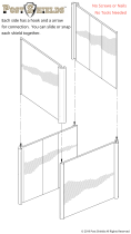
Connector information, pin assignments and mechanical specifications can be found in
Appendix A. Common sensor wiring schematics are shown in Appendix C. Please see your
packing list for your hardware’s specifications.
Sensor interface
connector
System connector

SLICE6 AIR DAS User’s Manual February 2020
support.dtsweb.com 6 13006-90440-MAN (Rev. 1)
Sensor Interface
The SLICE6 AIR DAS supports 6 sensor measurement
channels via the 51-pin, micro-D sensor interface connector.
See Appendix A for sensor connector pin assignments.
2019-2020 © Diversified Technical Systems, Inc. All Rights Reserved.
SLICE6 AIR DAS Sensor Interface
Supported Sensor Types
The SLICE6 AIR DAS supports many types of sensors including accelerometers, load cells
and pressure sensors. The following general sensor types are supported:
• Full- bridge (4-wire) or half-bridge (3-wire) resistive and piezo-resistive sensors
• IEPE sensors
• Conditioned sensors with 5 V excitation and an output voltage of 0-5 V.
For additional questions regarding supported sensors, please contact DTS and provide the
sensor manufacturer and model number, if available. For specific implementation
schematics, see Appendix C.
Input Range
The nominal sensor input range for bridge and piezo-resistive sensors is 0-5 V
1
(2.5 V center
with respect to -Ex) at a gain of 1. The sensor input range for IEPE sensors is 0.5-23.5 V.
At higher gains, the maximum range decreases correspondingly. For example, at a gain of
10, the input range is ±240 mV. (The software will automatically calculate the gain based on
the user-specified input range and other sensor parameters.)
1
Larger ranges supported with range expander cable. Contact DTS for more information.

SLICE6 AIR DAS User’s Manual February 2020
support.dtsweb.com 7 13006-90440-MAN (Rev. 1)
Excitation Sources
Bridge excitation sources are fixed and independently current limited at 5 V, 20 mA. IEPE
excitation is supported with a constant current of 5 mA with a source voltage of 24 V.
Excitation sources are not enabled until the software initializes the system during diagnostics.
Bridge Completion
Half-bridge emulation for any channel may be selected via software. Half-bridge transducers
should be connected to ±Ex and -Sig.
Hardware Filters
Each measurement channel has a fixed-frequency, 50 kHz, 4-pole and an adjustable 5-pole
Butterworth anti-aliasing filter supporting 1 Hz-40 kHz. Should you have any questions
regarding the best filter option for your application, please contact DTS.
Offset Compensation
Each channel can compensate for a sensor offset of up to 100% of the full-range output of a
sensor. The sensor offset is measured and the hardware compensation is adjusted during
the diagnostic check. Please see the software manual for additional information.
Electronic Identification (EID)
Each measurement channel supports communication with silicon serial number devices
manufactured by Dallas Semiconductor/Maxim Integrated Products (1-wire devices such as
DS2401 and DS2431). When an ID chip is connected to the proper pins on the sensor
connector, the software can automatically read these devices and correlate the serial number
to channel set-up information stored in the sensor database.
Shunt Emulation
The SLICE6 AIR DAS contains a shunt emulation circuit, effectively eliminating the need for
conventional shunt resistors to perform shunt checks. When “Emulation” is chosen as the
shunt calibration method, the software injects a precisely-calculated current into the sensor
to create an expected deflection of the sensor's output. Expected versus actual deflection
are compared to validate that the channel is working properly. Please see the software
manual for additional information.

SLICE6 AIR DAS User’s Manual February 2020
support.dtsweb.com 8 13006-90440-MAN (Rev. 1)
System Connector
All communications, control signals and input power are
provided via the 25-pin, micro-D system connector. Using
a SLICE6 AIR Chain Module or other interface, multiple
units can be interconnected (daisy-chained) for hundreds of
test channels.
Ethernet signals must be connected in series with a maximum cable length of ~10 m. (Cable
quality may affect maximum length and performance.) Control signals must be connected in
parallel. See Appendix A for pin assignments.
Communication Method
The SLICE6 AIR DAS supports Ethernet PTPv2 communications (IEEE1588). PTP
(Precision Timing Protocol) provides standards for precision clock synchronization for
measurement and control systems via Ethernet network communications. Timing
information is extracted from the network’s master clock and used by the SLICE6 AIR DAS
to adjust their internal (local) clock, providing precision timing for high channel-count systems
with a sampling synchronization better than 10 µs. Communication is enabled after the
initialization sequence has completed (~15 s after sufficient power and ON signal is applied).
(Note network congestion may slow IP address acquisition.)
Timing Synchronization
System-wide, channel-to-channel, time source synchronization is supported using
IRIG-B122, GPS and 1 PPS. Serial data (RS232 or RS422) from an external GPS source
can be recorded, and 1 PPS may be used with or without GPS.
Power Management
A good power source is of paramount importance. SLICE6 AIR DAS should be powered
from a high-quality power supply. Be sure to consider any power drop due to cable length.
Power Consumption (on 1588 network)
Input Voltage
Idle
IEPE off;
Armed and Recording
IEPE on;
Armed and Recording
9-30 VDC
2
<1.5 W
<2.7 W
<3.3 W
The SLICE6 AIR DAS does not contain an internal battery and must be connected to external
power at all times for operation. Without external power applied, the SLICE6 AIR DAS is in
a power off state.
When the unit is on (sufficient power and ON signal applied), power consumption depends
largely on the connected sensor load and whether the unit is armed.
2
Commercially-available 9 V batteries should not be used to power the SLICE6 AIR DAS.

SLICE6 AIR DAS User’s Manual February 2020
support.dtsweb.com 9 13006-90440-MAN (Rev. 1)
Power-up and Power-down Procedures
When sufficient power is applied, the SLICE6 AIR DAS will power up (on, idle and communi-
cation enabled) if an ON signal is present. With power applied but the ON signal absent, the
unit is off. Power up (On state) occurs in ~15 s, after which communication is enabled.
Power down of the DAS is immediate upon removal of either the ON signal or external power.
Wait ~30 s before reinitializing the DAS.
LEDs
The SLICE6 AIR DAS has a two LED indicators that show
system and power status.
Status (STS) LED
The status LED indicates communication and arm status and is red, green or blue. At system
power up, the LED cycles from red to green to blue followed immediately by the power LED
boot-up sequence.
Action
Result
Power up
Communicating with PC
Recording Data (Recorder Mode) -or- Armed (Circular Buffer) -or-
Real-Time Streaming
Armed in Recorder Mode
Unit received Event
Idle
• When the unit is not armed, the status LED will blink green when handling a
command from the PC.
• For Recorder Mode:
- When the unit is first armed, the LED will go solid blue to indicate that it is waiting
for the START RECORD signal but not taking data.
- When it receives the START RECORD signal, the LED will turn green to indicate
that it is actively recording data.
- The LED will turn off when data collection has completed.
- If an EVENT signal is received while the unit is recording data, the LED will turn
red and then turn off when data collection has completed.
• For Circular Buffer Mode:
- When the unit is armed, the LED will go solid green to indicate that it is collecting
data and waiting for the EVENT signal.
- When an EVENT signal is received the LED will turn red and then turn off when
data collection has completed.

SLICE6 AIR DAS User’s Manual February 2020
support.dtsweb.com 10 13006-90440-MAN (Rev. 1)
Power (PWR) LED
The power LED is red, green or blue.
Action
Result
Power up
Connected to host
Power up; not connected to host
Power fault (input power out of range)
• At power up, the LED cycles from red to green to blue immediately after the status
LED has completed its boot-up sequence.
• When connected to host, the LED will turn blue.
• At power up but not connected to host, the LED will turn green.
• When input power is too high or too low, the LED will turn red.

SLICE6 AIR DAS User’s Manual February 2020
support.dtsweb.com 11 13006-90440-MAN (Rev. 1)
Data Memory Size
With 15 GB of flash memory available for data storage, the SLICE6 AIR DAS can record
~52 minutes of data at the maximum sampling rate (6 channels at 400,000 sps). Since the
recording capacity is very large, it is generally best to limit sampling rates and event durations
to the minimum necessary to avoid large and cumbersome data files. Large files take longer
to download and may also be time-consuming to post-process or difficult to share. Use of
the Region of Interest (ROI) download can save a great deal of time if implemented properly.
Sampling Rates
User-selectable sampling rates are available from 50 sps to 400,000 sps.
# of
Channels*
Maximum Sampling Rate
(per channel)
6
400,000 samples per second (sps) via record in place
20,000 sps via data streaming
* All channels are recorded even if they are not programmed.
With 15 GB available for data storage, there are 7,500 M samples available (1 sample =
2 bytes). To determine the maximum recording time, divide the number of samples by the
product of the sampling rate and the number of channels.
7,500,000,000
= # of seconds
Sampling rate (sps) X # of channels
Example: 6 channels of data at 400,000 sps
7,500,000,000
= 3,125 sec (52 minutes)
400,000 X 6
Circular Buffer Limitations
Due to the nature of flash memory, the system cannot be armed in Circular Buffer mode
indefinitely. To determine the maximum time available, use the equation below:
0.8 recording time = maximum time available in Circular Buffer mode
Example: 0.8 3,125 sec = 2500 sec (41 minutes)
In this example, the test must occur within 41 minutes, after which time the unit stops
recording data.

SLICE6 AIR DAS User’s Manual February 2020
support.dtsweb.com 12 13006-90440-MAN (Rev. 1)
Basic Care and Handling
SLICE6 AIR systems are precision devices designed to operate reliably in dynamic testing
environments. Though resistant to many environmental conditions, care should be taken not
to subject the units to harsh chemicals, submerge it in water, or drop it onto any hard surface.
WARNING:
Electronic equipment dropped from desk height onto a solid
floor may experience up to 10,000 g. Under these conditions,
damage to the exterior and/or interior of the unit is likely.
Your SLICE6 AIR DAS module is supplied with calibration data from the factory. DTS
recommends annual recalibration to ensure that the unit is performing within factory
specifications. The SLICE6 AIR DAS is not user-serviceable and should be returned to the
factory for service or repair.
Shock Rating
Each SLICE6 AIR DAS is rated for 500 g, 3 ms half-sine duration, in all axes.
Mounting Considerations
SLICE6 AIR equipment should be bolted securely to the test article or dynamic testing device
to provide the best shock protection. Mounting methods and hardware selection should be
carefully calculated to withstand expected shock loading and facilitate proper grounding.
Check bolt tightness periodically to ensure that the unit is securely fastened to the testing
platform.
DTS strongly recommends that all equipment be properly grounded to minimize any risk of
data noise due to high-current transients. The test article or dynamic testing device should
be connected to earth ground. SLICE6 AIR equipment should be grounded to each other
and bolted to the test article. DTS recommends checking continuity between the enclosures
of each unit to confirm resistance readings of <1 ohm.
Thermal Considerations
The SLICE6 AIR DAS is a low power device and it is unlikely that self-heating will be an issue
in real-world testing if proper mounting methods are observed. Never mount the unit to a
thermally non-conductive surface like wood or plastic. ALWAYS use SLICE6 AIR DAS with
a heat sink if you are not mounting the system to a structure that will serve this purpose.
Should you have any questions about using SLICE in your environment, please contact DTS.

SLICE6 AIR DAS User’s Manual February 2020
support.dtsweb.com 13 13006-90440-MAN (Rev. 1)
Environmental Rating
The SLICE6 AIR DAS is IP65 rated:
6 (solid ingress) = totally protected against dust;
5 (liquid ingress) = protected against low pressure water jets from
any direction.
Care should be taken to prevent prolonged exposure to any potentially harmful environment.
Units should be cleaned, dried and inspected after exposure to any environment that could
cause damage.

SLICE6 AIR DAS User’s Manual February 2020
support.dtsweb.com 14 13006-90440-MAN (Rev. 1)
Software
DataPRO software is used with the SLICE6 AIR DAS. PC specifications are:
• Windows 7 and later (32- and 64-bit versions are supported)
• Microsoft .NET Runtime version 4.5.2
• MS Access ODBC drivers (usually included with Microsoft Office)
• i5 processor minimum; i7 processor recommended
• 8 GB RAM minimum; 16 GB RAM recommended (more RAM is important for high
channel counts and longer/higher sample rates)
• 1 GB disk space for software plus additional storage for test data
• 1366 x 768 minimum screen resolution; 1920 x 1080 recommended
Additionally, DTS recommends a network that supports gigabit Ethernet (GbE).
Data Collection Concepts
The discussion below provides a general introduction to data collection. Please see the
software manual for a detailed discussion and implementation specifics.
The SLICE6 AIR DAS is a standalone data logger. Once the system is armed, the PC can
be disconnected if desired. After receiving a Start Record or Event signal, SLICE
autonomously collects data, storing it to flash memory with no user interaction. After the test,
the user reconnects the PC to download the data.
There is also a real-time mode in the control software that allows the user to check channel
inputs on an oscilloscope-looking screen. (This data can be logged.)
Data Collection Modes
The SLICE6 AIR DAS supports 4 data collection modes: Circular Buffer, Recorder, Hybrid
Recorder, and Continuous Recorder. (Note: The software cannot simultaneously display
the data while the system is recording.)
Circular Buffer Mode
Using Circular Buffer mode, the user can program the SLICE6 AIR DAS to record pre- and
post-Event data. Time Zero (T=0) is marked when the Event signal is received.
Due to the nature of flash memory, the system cannot be armed in Circular Buffer mode
indefinitely. Please see page 11 for information on how to calculate data storage duration
when using Circular Buffer mode.
Recorder Mode
Data collection begins when a Start Record signal is received and continues for the time
specified in the test set-up. If an Event signal is received sometime after the Start Record
signal, this is marked as T=0.

SLICE6 AIR DAS User’s Manual February 2020
support.dtsweb.com 15 13006-90440-MAN (Rev. 1)
Hybrid Recorder Mode
Data collection begins when a Start Record signal is received and continues until the unit
receives an Event signal. The unit then records for the post-Event time specified by the user.
The Event signal marks the T=0 point and all data recorded is available for download.
Continuous Recorder Mode
Data collection begins when a Start Record signal is received and continues until the Start
Record signal is released. The unit will then re-arm for another event. The LEDs on the unit
will flash blue slowly then rapidly, and then the status LED will become solid blue, indicating
the unit is fully armed. The unit will continue to record new events until it records the number
of events specified by the user. If an Event signal is received after the unit has re-armed,
the unit will disarm and no longer attempt to re-arm.
NOTE:
An event or trigger signal applied anywhere in the SLICE6 AIR
DAS chain is distributed throughout the chain.
Data Streaming
Real-time data streaming up to 20,000 sps using IRIG Chapter 10 or TmNS is supported via
DataPRO software. Please see the software manual for additional information, including how
to create a test set-up.
Start Record and Event Initiation
The SLICE6 AIR DAS supports multiple methods of initiating Start Record and Event signals.
Typically, Start Record and Event are initiated via an external hardware interface that
provides a discrete contact closure (CC) signal to initiate recording (Recorder mode) or mark
T=0 (Circular Buffer mode).
All SLICE6 AIR DAS data collection modes support multi-event arming. A unit armed in a
multiple-event mode will re-arm when an event completes. The unit will stop re-arming when
the number of events specified by the user has been recorded.
The SLICE6 AIR DAS can be placed in an auto-arm mode that will cause the unit to arm
automatically when the power is cycled. This available with any available data collection
mode.
Additionally, Circular Buffer mode supports level triggering. This method continuously
samples the incoming data and begins data collection if the data is above or below predefined
levels. For example, it might be useful to begin data collection when a certain accelerometer
experiences a force above 200 g. Using level trigger and Circular Buffer mode, SLICE6 AIR
DAS can support this or any level-trigger signal on any channel.

SLICE6 AIR DAS User’s Manual February 2020
support.dtsweb.com 16 13006-90440-MAN (Rev. 1)
CAUTION:
Level trigger is NOT recommended when SLICE6 AIR DAS is
used for destructive testing.
Finally, if the SLICE6 AIR DAS remains connected to the PC during data collection, the
control software can be used to initiate data collection.
The table below summarizes the data collection modes and event/triggering options.
Supports T=0
Start Record
T=0 methods
supported
Data record window
Circular Buffer
Yes
Hardware (CC),
software (PC) or
level trigger
User-defined pre- and post- T=0
durations
Recorder
Yes
Hardware (CC),
software (PC) or
level trigger
User-defined duration after T=0
Hybrid Recorder
Yes
Hardware (CC),
software (PC) or
level trigger
User-defined post-Event duration
Continuous
Recorder
Yes
Hardware (CC),
software (PC), or
level trigger
User-defined duration after T=0,
with recording multiple events
possible

A
B
C
D
A
B
C
D
8
7
6
5
4 3
2
1
8
7
6
5
4 3 2 1
MDL:
DTS_SLICE6_AIR
DRW:
DTS_SLICE6_AIR_MOUNTING
DATE:
SEAL BEACH, CA 90740
562-493-0158
www.dtsweb.com
MATERIAL:
UNLESS OTHERWISE SPECIFIED:
UNITS = MM [INCH]
DIMENSIONAL TOLERANCES
.254 [0.010"]
INTERPRET PER ASME Y14.5. DO NOT SCALE.
SCALE:
SIZE:
SHEET:
DRAWN:
DTS P/N:
DESCRIPTION:
REV:
1 OF 1
This drawing contains information that is the property of Diversified Technical Systems, Inc. (DTS).
All copyright, patent, and ownership rights are retained. This information shall not be disclosed,
reproduced in whole or in part, or used for manufacture without prior written consent from DTS.
INTELLECTUAL PROPERTY STATEMENT
REV ZONE DESCRIPTION DATE BY
B
Manufacture/fabricate to meet the EU RoHS Directive
2011/65/EU and RoHS Annex II phthalates
RoHS
2X 6,36 0.250[ ]
0,00 0.000[ ]
2X 35,64 1.403[ ]
42,00 1.654[ ]
6,46 0.254[ ]
0,00 0.000[ ]
12,81 0.504[ ]
2X 35,54 1.399[ ]
42,00 1.654[ ]
4X R1,6 [0.06]
4X 2,70 [0.106] THRU
MOUNT USING M2.5 OR 2-56 BOLTS
(49,53 [1.950])
0,50 [0.020]13,00 0.512[ ]
0,00 0.000[ ]
2X 6,50 0.256[ ]
40,00 [1.575]
0,05 [0.002]
2X 9,53 [0.375]
38,60 [1.520]
2X 17,00 0.669[ ]
2X 25,00 0.984[ ]
4X
6,40 [0.252]
(51,7 [2.04])
2X R0,50 [0.020]
SLICE6 AIR,
MOUNTING DRAWING
0
G NEWTON
2019-02-01
1:1
6061-T6 ALUMINUM W/
INTERNATIONAL ORANGE ANODIZE
PIN SIGNAL
1 +PWR
2 +PWR
3 +PWR
4 GND
5 GND
6 TX_2_P
7 TX_2_N
8 RX_2_P
9 RX_2_N
10 TX_1_P
11 TX_1_N
12 RX_1_P
13 RX_1_N
14 #ON
15 #START
16 #EVENT
17 STATUS
18 UART_RX_P
19 UART_RX_N
20 UART_TX_P
21 UART_TX_N
22 GND
23 GND
24 IRIGB
25 PPS
PIN SIGNAL
1 -SIG_CH1
2 +SIG_CH1
3 GND/SHIELD
4 -SIG_CH2
5 +SIG_CH2
6 GND/SHIELD
7 -SIG_CH3
8 +SIG_CH3
9 -ID/-IEPE_CH3
10 -ID/-IEPE_CH4
11 +SIG_CH4
12 -SIG_CH4
13 GND/SHIELD
14 +SIG_CH5
15 -SIG_CH5
16 GND/SHIELD
17 +SIG_CH6
18 -SIG_CH6
19 -EX_CH1
20 +IEPE_CH1
21 GND/SHIELD
22 -EX_CH2
23 +IEPE_CH2
24 GND/SHIELD
25 -EX_CH3
26 +IEPE_CH3
27 GND/SHIELD
28 +IEPE_CH4
29 -EX_CH4
30 GND/SHIELD
31 +IEPE_CH5
32 -EX_CH5
33 GND/SHIELD
34 +IEPE_CH6
35 -EX_CH6
36 +EX_CH1
37 +ID_CH1
38 -ID/-IEPE_CH1
39 +EX_CH2
40 +ID_CH2
41 -ID/-IEPE_CH2
42 +EX_CH3
43 +ID_CH3
44 +ID_CH4
45 +EX_CH4
46 -ID/-IEPE_CH5
47 +ID_CH5
48 +EX_CH5
49 -ID/-IEPE_CH6
50 +ID_CH6
51 +EX_CH6
SENSOR
CONNECTOR
PIN ASSIGNMENTS
SYSTEM
CONNECTOR
PIN ASSIGNMENTS
--- CONNECTOR MATE RECOMMENDATIONS ---
51-Socket Sensor Connector:
Omnetics MMDS-513-N-02-SS (Solder Cup)
Omnetics MMDS-513-N-02-WD** (Discrete Wire)
25-Pin System Connector:
Omnetics MMDP-025-N-02-SS (Solder Cup)
Omnetics MMDP-025-N-02-WD** (Discrete Wire)
** See ordering options on manufacturer website for
wire gage, type, color, and length options
LOOKING INTO FRONT OF SLICE6 AIR
SYSTEM CONNECTOR
LOOKING INTO FRONT OF SLICE6 AIR
SENSOR CONNECTOR
MASS = 50 5 GRAMS
SYSTEM CONNECTOR
25-SOCKET MICRO-D
SERIAL NUMBER
STATUS LED
POWER LED
SENSOR CONNECTOR
51-PIN 3-ROW MICRO-D

SLICE6 AIR DAS User’s Manual February 2020
support.dtsweb.com 18 13006-90440-MAN (Rev. 1)
Ethernet Chaining
To share Ethernet communications, chain SLICE6 AIR DAS modules together using the
methodology in the table below.
SLICE6 AIR DAS #1
SLICE6 AIR DAS #2
SLICE6 AIR DAS #3
Function
Pin
Function
Pin
Function
Pin
TX_2_P
6
RX_1_P
12
TX_2_N
7
RX_1_N
13
RX_2_P
8
TX_1_P
10
RX_2_N
9
TX_1_N
11
TX_2_P
6
RX_1_P
12
TX_2_N
7
RX_1_N
13
RX_2_P
8
TX_1_P
10
RX_2_N
9
TX_1_N
11
Accessories/Support Equipment
10400-00060: Power supply; 15 VDC, 4 A (90-240 VAC in, LEMO termination) (PS-05)
13006-90450: SLICE6 AIR Bridge Plug
13006-90460: SLICE6 AIR Chain Module
3
13006-9047x: Cable, SLICE6 AIR DAS extension (26-pin to 26-socket)
13006-90480: SLICE6 AIR Interface Device
13006-90510: SLICE6 AIR Ethernet Return Plug
4
13006-90520: SLICE6 AIR Interface Device and Cable Kit
99000-00418-R: Nut driver, precision, 3/16" hex; 6-1/8"L
(x = multiple lengths available)
3
To connect individual chain modules (P/N 13006-90460) to each other, the standoffs on the socket side
must be removed. Retain the screws for future use. (They are required to use/secure a return plug
P/N 13006-90510.)

SLICE6 AIR DAS User’s Manual February 2020
support.dtsweb.com 19 13006-90440-MAN (Rev. 1)
Appendix B: Hardware Configuration Specifications
SLICE6 AIR DAS are typically delivered with a default IP address as follows:
IP address
192.168.4.xx where xx is based on the last two digits of the S/N; for example:
S/N S6A0047 = 192.168.4.47
S/N S6A0233 = 192.168.4.33
Netmask
255.255.248.0
The calibration data for your equipment identifies the IP address as shipped from the factory.
If the calibration data is not available, try using the default address described in the table
above.
If you need information on the specifics of your equipment, please submit a request through
the DTS Help Center web portal (support.dtsweb.com) and include the serial number(s) of
the equipment and parameters you are asking about.
Using the SLICE Network Configuration Utility
The SLICE Network Configuration Utility (available from the DTS Help Center) can be used
to view or change the unit’s IP address.
Use of the utility requires a network that supports multicast and the workstation running the
utility must also allow it. Confirm that:
• The PC’s Ethernet properties are not using anything that can block multicast; e.g.,
DNE LightWeight Filter.
• The Windows Firewall will allow multicast traffic.
• Any third-party anti-virus software will allow multicast traffic.
1. Open the SLICE Network Configuration Utility.

SLICE6 AIR DAS User’s Manual February 2020
support.dtsweb.com 20 13006-90440-MAN (Rev. 1)
2. The software will immediately look for all attached devices and list them in the table.
(You may also click to refresh the list.)
Note: Clicking on for any selected device will cause the unit’s LED to flash.
3. Select the SLICE6 device from the list. (A SLICE6 DAS is selected in the image
above.) The device Settings are shown at the bottom of the window. The current IP
address may or may not match the fallback IP address, depending on whether DHCP
is selected.
Current IP address
/