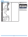
Shimano RD-M6000 is a rear derailleur designed for precise and smooth shifting on mountain bikes. With its Shadow RD+ design, it offers improved chain stability and reduced chain slap. It features a wide gear range compatibility, allowing you to tackle various terrains and gradients. The RD-M6000 also comes with an adjustable B-screw for fine-tuning the derailleur's position relative to the cassette.
Shimano RD-M6000 is a rear derailleur designed for precise and smooth shifting on mountain bikes. With its Shadow RD+ design, it offers improved chain stability and reduced chain slap. It features a wide gear range compatibility, allowing you to tackle various terrains and gradients. The RD-M6000 also comes with an adjustable B-screw for fine-tuning the derailleur's position relative to the cassette.


-
 1
1
-
 2
2
-
 3
3
-
 4
4
-
 5
5
-
 6
6
-
 7
7
-
 8
8
-
 9
9
-
 10
10
-
 11
11
-
 12
12
-
 13
13
-
 14
14
-
 15
15
-
 16
16
-
 17
17
-
 18
18
-
 19
19
-
 20
20
-
 21
21
-
 22
22
-
 23
23
-
 24
24
-
 25
25
-
 26
26
-
 27
27
-
 28
28
-
 29
29
-
 30
30
-
 31
31
-
 32
32
-
 33
33
-
 34
34
-
 35
35
-
 36
36
-
 37
37
-
 38
38


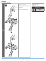
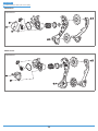
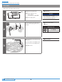
Shimano RD-M6000 Dealer's Manual
- Type
- Dealer's Manual
Shimano RD-M6000 is a rear derailleur designed for precise and smooth shifting on mountain bikes. With its Shadow RD+ design, it offers improved chain stability and reduced chain slap. It features a wide gear range compatibility, allowing you to tackle various terrains and gradients. The RD-M6000 also comes with an adjustable B-screw for fine-tuning the derailleur's position relative to the cassette.
Ask a question and I''ll find the answer in the document
Finding information in a document is now easier with AI
Related papers
-
Shimano RD-M280 Dealer's Manual
-
Shimano RD-M5120 Dealer's Manual
-
Shimano SL-M3100 Dealer's Manual
-
Shimano FD-M4100 Dealer's Manual
-
Shimano FD-RX400 Dealer's Manual
-
Shimano SW-R671 User manual
-
-
Shimano FD-T6000 Dealer's Manual
-
Shimano SL-RS700 Dealer's Manual
-
Shimano RD-M8100 User manual


