
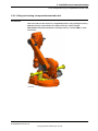
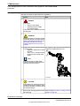
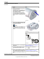
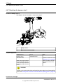
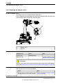
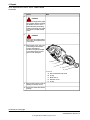
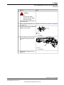
ROBOTICS
Product manual
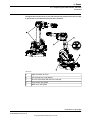
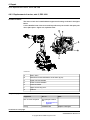
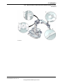
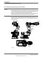
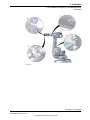
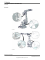
IRB 1600/1660

Trace back information:
Workspace R18-2 version a18
Checked in 2018-11-20
Skribenta version 5.3.012

Product manual
IRB 1600 - 5/1.2 type A
IRB 1600 - 5/1.45 type A
IRB 1600 - 6/1.2 type A
IRB 1600 - 6/1.45 type A
IRB 1600 - 7/1.2 type A
IRB 1600 - 7/1.45 type A
IRB 1600 - 8/1.2 type A
IRB 1600 - 8/1.45 type A
IRB 1600 - 10/1.2 type A
IRB 1600 - 10/1.45 type A
IRB 1600ID - 4/1.5
IRB 1600ID - 4/1.5 type A
IRB 1660ID - 6/1.55
IRB 1660ID - 4/1.55
IRC5
Document ID: 3HAC026660-001
Revision: W
© Copyright 2006-2018 ABB. All rights reserved.
Specifications subject to change without notice.

The information in this manual is subject to change without notice and should not
be construed as a commitment by ABB. ABB assumes no responsibility for any errors
that may appear in this manual.
Except as may be expressly stated anywhere in this manual, nothing herein shall be
construed as any kind of guarantee or warranty by ABB for losses, damages to
persons or property, fitness for a specific purpose or the like.
In no event shall ABB be liable for incidental or consequential damages arising from
use of this manual and products described herein.
This manual and parts thereof must not be reproduced or copied without ABB's
written permission.
Keep for future reference.
Additional copies of this manual may be obtained from ABB.
Original instructions.
© Copyright 2006-2018 ABB. All rights reserved.
Specifications subject to change without notice.
ABB AB, Robotics
Robotics and Motion
Se-721 68 Västerås
Sweden

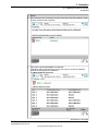
Table of contents
9Overview of this manual ...................................................................................................................
15Product documentation ....................................................................................................................
17How to read the product manual ......................................................................................................
191 Safety
191.1 General safety information ..................................................................................
191.1.1 Limitation of liability .................................................................................
211.1.2 Protective stop and emergency stop ...........................................................
221.2 Safety actions ...................................................................................................
221.2.1 Fire extinguishing ....................................................................................
231.2.2 Emergency release of the robot axes ..........................................................
241.2.3 Make sure that the main power has been switched off ....................................
251.3 Safety risks ......................................................................................................
251.3.1 Safety risks during installation and service work on robots ..............................
271.3.2 Moving robots are potentially lethal ............................................................
281.3.3 First test run may cause injury or damage ....................................................
291.3.4 Work inside the working range of the robot ..................................................
301.3.5 Enabling device and hold-to-run functionality ...............................................
311.3.6 Risks associated with live electric parts .......................................................
331.3.7 The unit is sensitive to ESD .......................................................................
341.3.8 Hot parts may cause burns .......................................................................
351.3.9 Safety risks related to pneumatic/hydraulic systems ......................................
361.3.10 Brake testing ..........................................................................................
371.3.11 Safety risks during handling of batteries ......................................................
381.3.12 Safety risks during work with gearbox lubricants (oil or grease) .......................
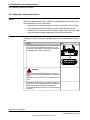
401.4 Safety signals and symbols .................................................................................
401.4.1 Safety signals in the manual ......................................................................
421.4.2 Safety symbols on product labels ...............................................................
492 Installation and commissioning
492.1 Introduction ......................................................................................................
502.2 Unpacking .......................................................................................................
502.2.1 Pre-installation procedure .........................................................................
552.2.2 Working range ........................................................................................
612.2.3 Risk of tipping/stability .............................................................................
632.3 On-site installation ............................................................................................
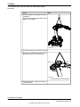
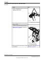
632.3.1 Lifting robot with roundslings ....................................................................
652.3.2 Lifting and turning a suspended mounted robot ............................................
662.3.3 Manually releasing the brakes ...................................................................
682.3.4 Orienting and securing the robot ................................................................
722.3.5 Setting the system parameters for a suspended or tilted robot .........................
782.3.6 Loads fitted to the robot, stopping time and braking distances .........................
792.3.7 Fitting equipment on the robot (robot dimensions) .........................................
922.3.8 Installation of signal lamp for 1600 (option) ..................................................
952.3.9 Installation of signal lamp for 1600ID/1660ID (option) .....................................
972.3.10 Installation of the wire feeder shelf for 1600ID/1660ID ....................................
992.4 Restricting the working range ..............................................................................
992.4.1 Axes with restricted working range .............................................................
1002.4.2 Installation of additional mechanical stops on axis 1 ......................................
1052.4.3 Installation of additional mechanical stop on axis 2 ........................................
1092.4.4 Installation of additional mechanical stops on axis 3 ......................................
1132.4.5 Installation of position switch, axis 1 ...........................................................
1162.5 Electrical connections ........................................................................................
1162.5.1 Customer connectors on the robot .............................................................
1192.5.2 Robot cabling and connection points ..........................................................
1232.5.3 Customer connections on the robot ............................................................
Product manual - IRB 1600/1660 5
3HAC026660-001 Revision: W
© Copyright 2006-2018 ABB. All rights reserved.
Table of contents

1262.6 Start of robot in cold environments ......................................................................
1273 Maintenance
1273.1 Introduction ......................................................................................................
1283.2 Maintenance schedule and expected component life ...............................................
1283.2.1 Specification of maintenance intervals ........................................................
1293.2.2 Maintenance schedule .............................................................................
1313.2.3 Expected component life ..........................................................................
1323.3 Inspection activities ...........................................................................................
1323.3.1 Inspection, damper axes 2, 3 and 5 .............................................................
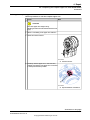
1353.3.2 Inspecting information labels .....................................................................
1373.4 Replacement activities .......................................................................................
1373.4.1 Type of lubrication in gearboxes ................................................................
1383.4.2 Changing the oil in axes 5 and 6 gearboxes .................................................
1413.4.3 Changing the oil in axes 5 and axis 5 and 6 gearboxes, IRB 1600ID/1660ID ........
1443.4.4 Replacing the battery pack ........................................................................
1493.5 Cleaning activities .............................................................................................
1493.5.1 Cleaning the IRB 1600/1660ID ...................................................................
1534 Repair
1534.1 Introduction ......................................................................................................
1544.2 General procedures ...........................................................................................
1544.2.1 Performing a leak-down test ......................................................................
1554.2.2 Mounting instructions for bearings .............................................................
1574.2.3 Mounting instructions for seals ..................................................................
1594.2.4 Cut the paint or surface on the robot before replacing parts ............................
1614.2.5 The brake release buttons may be jammed after service work .........................
1624.3 Complete manipulator ........................................................................................
1624.3.1 Replacing the cable harness, IRB 1600 .......................................................
1724.3.2 Replacing the cable harness, 1600ID/1660ID ................................................
1784.3.3 Replacement of complete arm system .........................................................
1834.4 Upper and lower arm .........................................................................................
1834.4.1 Replacing the complete upper arm, IRB 1600 ...............................................
1884.4.2 Replacing the complete upper arm, IRB 1600ID/1660ID ..................................
1964.4.3 Replacing the complete lower arm ..............................................................
2014.4.4 Replacing the wrist unit, IRB 1600 ..............................................................
2064.4.5 Replacing the wrist unit, IRB 1600ID ...........................................................
2124.4.6 Replacing the wrist unit, IRB1660ID ............................................................
2204.4.7 Replacing the damper, axis 2 .....................................................................
2224.4.8 Replacing the damper, axis 3 .....................................................................
2244.4.9 Replacing the mechanical stop axis 3, IRB 1600ID/1660ID ..............................
2264.4.10 Replacement of damper, axis 5 ..................................................................
2284.4.11 Remove upper arm AW Gun ......................................................................
2334.4.12 Measuring the play 1600ID/1660ID, axis 5 ....................................................
2364.4.13 Measuring the play 1600ID/1660ID, axis 6 ....................................................
2394.5 Frame and base ................................................................................................
2394.5.1 Replacement of base ...............................................................................
2444.5.2 Replacing the serial measurement unit ........................................................
2514.5.3 Replacing the push button unit ..................................................................
2574.6 Motors ............................................................................................................
2574.6.1 Replacement of motor, axis 1 ....................................................................
2624.6.2 Replacement of motor, axis 2 ....................................................................
2684.6.3 Replacement of motor, axis 3, IRB 1600 ......................................................
2734.6.4 Replacement of motor, axis 3, 1600ID/1660ID ...............................................
2794.6.5 Replacement of motor, axis 4, IRB 1600 ......................................................
2844.6.6 Replacement of motor, axis 4, 1600ID/1660ID ...............................................
2884.6.7 Replacement of motor and timing belt, axis 5, IRB 1600 .................................
2944.6.8 Replacement of motor, axis 5, IRB 1600ID ...................................................
3024.6.9 Replacement of motor, axis 5, IRB 1660ID ...................................................
6 Product manual - IRB 1600/1660
3HAC026660-001 Revision: W
© Copyright 2006-2018 ABB. All rights reserved.
Table of contents

3114.6.10 Replacement of motor and timing belt, axis 6, IRB 1600 .................................
3154.6.11 Replacement of motor, axis 6, IRB 1600ID ...................................................
3194.6.12 Replacement of motor, axis 6, IRB 1660ID ...................................................
3294.7 Gearboxes .......................................................................................................
3294.7.1 Replacement of gearbox, axes 1-2 .............................................................
3354.7.2 Service work on gearboxes, axes 3, 4, 5 and 6 ..............................................
3375 Calibration
3375.1 Introduction to calibration ...................................................................................
3375.1.1 Introduction and calibration terminology ......................................................
3385.1.2 Calibration methods .................................................................................
3405.1.3 When to calibrate ...................................................................................
3415.2 Synchronization marks and axis movement directions .............................................
3415.2.1 Synchronization marks and synchronization position for axes .........................
3445.2.2 Calibration movement directions for all axes ................................................
3455.3 Updating revolution counters ...............................................................................
3495.4 Calibrating with Axis Calibration method ...............................................................
3495.4.1 Description of Axis Calibration ..................................................................
3525.4.2 Calibration tools for Axis Calibration ...........................................................
3545.4.3 Installation locations for the calibration tools ...............................................
3585.4.4 Axis Calibration - Running the calibration procedure ......................................
3665.5 Calibrating with Calibration Pendulum method ........................................................
3675.6 Verifying the calibration ......................................................................................
3685.7 Checking the synchronization position ..................................................................
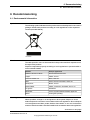
3696 Decommissioning
3696.1 Environmental information ..................................................................................
3716.2 Scrapping of robot .............................................................................................
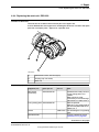
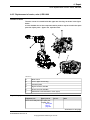
3737 Robot description
3737.1 Type A of IRB 1600 ............................................................................................
3747.2 Type A of IRB 1600ID .........................................................................................
3758 Reference information
3758.1 Introduction ......................................................................................................
3768.2 Applicable standards .........................................................................................
3788.3 Unit conversion .................................................................................................
3798.4 Screw joints ....................................................................................................
3828.5 Weight specifications .........................................................................................
3838.6 Standard tools ..................................................................................................
3848.7 Special tools ....................................................................................................
3868.8 Lifting accessories and lifting instructions ..............................................................
3879 Spare part lists
3879.1 Spare part lists and illustrations ...........................................................................
38910 Circuit diagram
38910.1 Circuit diagrams ................................................................................................
391Index
Product manual - IRB 1600/1660 7
3HAC026660-001 Revision: W
© Copyright 2006-2018 ABB. All rights reserved.
Table of contents

This page is intentionally left blank

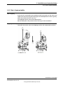
Overview of this manual
About this manual
This manual contains instructions for:
• mechanical and electrical installation of the robot
• maintenance of the robot
• mechanical and electrical repair of the robot.
Usage
This manual should be used during:
• installation, from lifting the robot to its work site and securing it to the
foundation, to making it ready for operation
• maintenance work
• repair work and calibration.
Who should read this manual?
This manual is intended for:
• installation personnel
• maintenance personnel
• repair personnel.
Prerequisites
Maintenance/repair/installation personnel working with an ABB Robot must:
• be trained by ABB and have the required knowledge of mechanical and
electrical installation/repair/maintenance work.
Product manual scope
The manual covers covers all variants and designs of the IRB 1600/1660ID. Some
variants and designs may have been removed from the business offer and are no
longer available for purchase.
Organization of chapters
The manual is organized in the following chapters:
ContentsChapter
Safety information that must be read through before performing
any installation or service work on robot. Contains general safety
aspects as well as more specific information on how to avoid
personal injuries and damage to the product.
Safety, service
Required information about lifting and installation of the robot.Installation and commis-
sioning
Step-by-step procedures that describe how to perform mainten-
ance of the robot. Based on a maintenance schedule that may
be used to plan periodical maintenance.
Maintenance
Step-by-step procedures that describe how to perform repair
activities of the robot. Based on available spare parts.
Repair
Continues on next page
Product manual - IRB 1600/1660 9
3HAC026660-001 Revision: W
© Copyright 2006-2018 ABB. All rights reserved.
Overview of this manual

ContentsChapter
Calibration procedures and general information about calibration.Calibration
Environmental information about the robot and its components.Decommissioning
Useful information when performing installation, maintenance
or repair work. Includes lists of necessary tools, additional doc-
uments, safety standards, etc.
Reference information
Complete spare part list and complete list of robot components,
shown in exploded views.
Spare parts and exploded
views
Reference to the circuit diagram for the robot.Circuit diagram
References
Documentation referred to in the manual, is listed in the table below.
Document IDDocument name
3HAC021351-003Circuit diagram - IRB 1600/1660
3HAC023604-001Product specification - IRB 1600/1660
3HAC049104-001Product manual, spare parts - IRB 1600/1660
3HAC031045-001Operating manual - General safety information
i
3HAC021313-001Product manual - IRC5
IRC5 with main computer DSQC 639.
3HAC047136-001Product manual - IRC5
IRC5 with main computer DSQC1000.
3HAC050941-001Operating manual - IRC5 with FlexPendant
3HAC050944-001Operating manual - Service Information System
3HAC16578-1Operating manual - Calibration Pendulum
3HAC051016-001Application manual - Additional axes and stand alone controller
3HAC030421-001Application manual - CalibWare Field 5.0
3HAC042927-001Technical reference manual - Lubrication in gearboxes
3HAC050948-001Technical reference manual - System parameters
3HAC028664-002Instructions lifting accessory 3HAC024483-001
i
This manual contains all safety instructions from the product manuals for the manipulators and the
controllers.
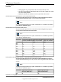
Revisions
DescriptionRevision
First edition. See also Type A of IRB 1600 on page 373.-
AW equipped upper arm 1600ID, IRB 1600-6/1.2, IRB 1600-6/1.45, IRB
1600-8/1.2 and IRB 1600-8/1.45 added.
A
Clean Room added.B
Changes made in:
• Prerequisites in section Overview
• Oil change in section Maintenance
Content updated in section:
• Making robot ready for operation, Clean Room / Additional install-
ation procedure.
C
Continues on next page
10 Product manual - IRB 1600/1660
3HAC026660-001 Revision: W
© Copyright 2006-2018 ABB. All rights reserved.
Overview of this manual
Continued

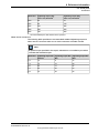
DescriptionRevision
Content updated in chapter/section:
• Maintenance/Cleaning of robot
• Maintenance/Maintenance schedule: Interval for replacement of
battery pack changed
• Section What is an emergency stop? added to chapter Safety.
D
Content updated in chapter/section:
• Maintenance/Oil in gearboxes: Amount of oil in gearboxes axes
1 and 2.
E
Content updated in sections:
• New graphics for equipment load areas, see Fitting equipment on
the robot (robot dimensions) on page 79.
• Instruction moved from chapter Repair to Installation, see Install-
ation of the wire feeder shelf for 1600ID/1660ID on page 97.
• Spare part list, updated regarding Foundry Plus Cable guard.
• Cleaning the IRB 1600/1660ID on page 149 in chapter Maintenance
updated.
• Sealing compound updated in Cut the paint or surface on the robot
before replacing parts on page 159.
• Decommissioning chapter added.
Updates in the chapter Safety:
• Updated safety signal graphics for the levels Danger and Warning,
see Safety signals in the manual on page 40.
• New safety labels on the manipulators, see Safety symbols on
product labels on page 42.
• Revised terminology: robot replaced with manipulator.
F
Content updated in sections:
• Added reference to lifting accessory, see Lifting and turning a
suspended mounted robot on page 65.
G
Content updated in sections:
• Added note about not inserting guide pin too far into the tool
flange, section Fitting equipment on the robot (robot dimensions)
on page 79.
• Updated spare part numbers, in sections: Base, frame, upper arm,
upper arm 1600ID and options.
• New and updated safety symbols, see Safety symbols on product
labels on page 42.
H
Continues on next page
Product manual - IRB 1600/1660 11
3HAC026660-001 Revision: W
© Copyright 2006-2018 ABB. All rights reserved.
Overview of this manual
Continued

DescriptionRevision
This revision includes the following updates:
• A new block, about general illustrations, added in section How to
read the product manual on page 17.
• Resolver connection added, connection for resolver signals axis
7 located on the base see section Customer connectors on the
robot on page 116
• Added an illustration that shows the directions of the robot stress
forces and changed the value for the force in the Z plane, see
Loads on foundation, robot on page 51.
• Improvements made in the instruction for replacing the complete
ID upper arm, see Replacing the complete upper arm, IRB
1600ID/1660ID on page 188.
• Gearboxes and motor pinions from SAMP are added to the spare
part lists together with a table that shows compability between
the motors and gearboxes, see Spare parts -Compatible gearboxes
and motors. The spare part numbers are also removed from the
Required equipment lists in the repair instructions for motors and
gearboxes, and instead replaced with links to the Spare parts
chapter.
• The option Foundry Plus Cable Guard is removed.
• Some general tightening torques have been changed/added, see
updated values in Screw joints on page 379.
• Corrected value for working range of wall mounted robots, added
working range for IRB 1600ID and updated a figure, see Working
range on page 55.
• Spare part numbers for axis-4, axis-5 and axis-6 motors for IRB
1600ID are corrected.
• Added Safety risks during handling of batteries on page 37.
J
This revision includes the following updates:
• Added range and capacity to the denomination of IRB 1600ID.
• Added information about IRB 1600ID type A, on first inside page
and as a new section Type A of IRB 1600ID on page 374.
• Spare part numbers for SAMP motors and upper arms are correc-
ted, see Spare parts - Compatible gearboxes and motors.
• Added variants IRB 1600 - 10/1.2 and IRB 1600 - 10/1.45 to the
manual.
• Updated loads on the foundation, see Loads on foundation, robot
on page 51.
• Corrected the appearance of figures in section Working range on
page 55.
• Changed maximum tilt from 60º to 55º, see Requirements,
foundation on page 52.
• All data about type of lubrication in gearboxes is moved from the
manual to a separate lubrication manual, see Type and amount
of oil in gearboxes on page 137.
• Added information about importance to install the robot with cor-
rect X direction in the base coordinate system, see Installation of
additional mechanical stops on axis 1 on page 100 and Setting the
system parameters for a suspended or tilted robot on page 72.
• A new SMB unit and battery is introduced, with longer battery
lifetime.
• Added mounting holes on the lower arm, see Fitting equipment
on the robot (robot dimensions) on page 79.
K
Continues on next page
12 Product manual - IRB 1600/1660
3HAC026660-001 Revision: W
© Copyright 2006-2018 ABB. All rights reserved.
Overview of this manual
Continued

DescriptionRevision
This revision includes the following updates:
• Spare numbers in general, updated/corrected.
• Spare number for Motor axis 3 (Rexnord) changed.
• Added information about risks when scrapping a decommissioned
robot, see Scrapping of robot on page 371.
• Base connections, illustration updated with new views.
• Updated tightening torque for the oil plug on axis 5-6 for IRB
1600ID, see Changing the oil in axes 5 and axis 5 and 6 gearboxes,
IRB 1600ID/1660ID on page 141.
• Spare parts and exploded views are not included in this document
but delivered as a separate document. See Product manual, spare
parts - IRB 1600/1660.
• Note about the placement of connectors in ID-upper arm added
in Repair instructions. See Replacement of motor, axis 5, IRB
1600ID on page 294 and Replacing the wrist unit, IRB 1600ID on
page 206.
• Note about handling the wrist during replacement added. See
Replacing the wrist unit, IRB 1600ID on page 206.
L
This revision includes the following updates:
• Changed article number for signal lamp, see Installation of signal
lamp for 1600 (option) on page 92.
• Added detailed view of the orientation of axis-5 motor, see Re-
placement of axis-5 motor.
• Minor corrections.
M
This revision includes the following updates:
• Added instructions for measuring the play in the ID wrist, see
Measuring the play 1600ID/1660ID, axis 5 on page 233, and Meas-
uring the play 1600ID/1660ID, axis 6 on page 236.
• Minor corrections.
N
This revision includes the following updates:
• Added a new variant IRB 1600ID - 6/1.55.
• Updated the loads on foundation, see Loads on foundation, robot
on page 51.
• Added maintenance activities for the grease oil in IRB 1600 axes
1 to 4.
P
This revision includes the following updates:
• Rename the new variant IRB 1600ID - 6/1.55 to IRB 1660ID - 6/1.55.
• Updated figure that shows cable bracket and cable tie of axis-2
motor cable on the frame, see Replacement of motor, axis 2 on
page 262.
Q
Published in release R16.2. The following updates are done in this revi-
sion:
• Added a new variant IRB 1660ID - 4/1.55.
• Wall mounting available to IRB 1660ID - X/1.55.
R
Published in release R17.1. The following updates are made in this revi-
sion:
• Updated the robot weight, see Weight, robot on page 51.
• New standard calibration method is introduced (Axis Calibration).
See Calibration on page 337.
• Information about grounding point is added, see Robot cabling
and connection points on page 119.
S
Continues on next page
Product manual - IRB 1600/1660 13
3HAC026660-001 Revision: W
© Copyright 2006-2018 ABB. All rights reserved.
Overview of this manual
Continued

DescriptionRevision
Published in release R17.2. The following updates are made in this revi-
sion:
• Information about coupled axes in Updating revolution counters
on page 345.
• Caution about removing metal residues added in sections about
SMB boards.
• Information added into calibration procedure regarding installation
of calibration tool on turning disc, see Overview of the calibration
procedure on the FlexPendant on page 358.
• Information about minimum resonance frequency added.
• Bending radius for static floor cables added.
• Updated list of applicable standards.
• Article number for the Calibration tool box, Axis Calibration is
changed.
• Section Start of robot in cold environments on page 126 added.
• Updated information regarding replacement of brake release
board.
• Updated information regarding lifting tool, upper arm, in section
Special tools on page 384.
• Updated information regarding disconnecting and reconnecting
battery cable to serial measurement board.
T
Published in release R18.1. The following updates are made in this revi-
sion:
• Information added about fatigue to Axis Calibration tool, see Cal-
ibration tools for Axis Calibration on page 352.
• Added sections in General procedures on page 154.
• Safety restructured.
• Updated spare part number brake release unit (was DSQC574, is
DSQC1054)
• Tool flange figure is updated.
• Note added to calibration chapter to emphasize the requirement
of equally dressed robot when using previously created reference
calibration values.
• Information about myABB Business Portal added.
• Added Nickel in environmental information.
U
Published in release R18.2. The following updates are done in this revi-
sion:
• Updated information of holes for mounting of extra equipment for
IRB 1600, see Holes for mounting of extra equipment for IRB 1600
on page 84.
• Added section for inspection of labels in maintenance chapter.
• Updated information regarding o-ring replacement for axis-1 and
axis-2 motors.
V
Published in release R18.2. The following updates are done in this revi-
sion:
• Updated reference.
W
14 Product manual - IRB 1600/1660
3HAC026660-001 Revision: W
© Copyright 2006-2018 ABB. All rights reserved.
Overview of this manual
Continued

Product documentation
Categories for user documentation from ABB Robotics
The user documentation from ABB Robotics is divided into a number of categories.
This listing is based on the type of information in the documents, regardless of
whether the products are standard or optional.
All documents can be found via myABB Business Portal, www.myportal.abb.com.
Product manuals
Manipulators, controllers, DressPack/SpotPack, and most other hardware is
delivered with a Product manual that generally contains:
• Safety information.
• Installation and commissioning (descriptions of mechanical installation or
electrical connections).
• Maintenance (descriptions of all required preventive maintenance procedures
including intervals and expected life time of parts).
• Repair (descriptions of all recommended repair procedures including spare
parts).
• Calibration.
• Decommissioning.
• Reference information (safety standards, unit conversions, screw joints, lists
of tools).
• Spare parts list with corresponding figures (or references to separate spare
parts lists).
• References to circuit diagrams.
Technical reference manuals
The technical reference manuals describe reference information for robotics
products, for example lubrication, the RAPID language, and system parameters.
Application manuals
Specific applications (for example software or hardware options) are described in
Application manuals. An application manual can describe one or several
applications.
An application manual generally contains information about:
• The purpose of the application (what it does and when it is useful).
• What is included (for example cables, I/O boards, RAPID instructions, system
parameters, software).
• How to install included or required hardware.
• How to use the application.
• Examples of how to use the application.
Continues on next page
Product manual - IRB 1600/1660 15
3HAC026660-001 Revision: W
© Copyright 2006-2018 ABB. All rights reserved.
Product documentation

Operating manuals
The operating manuals describe hands-on handling of the products. The manuals
are aimed at those having first-hand operational contact with the product, that is
production cell operators, programmers, and troubleshooters.
16 Product manual - IRB 1600/1660
3HAC026660-001 Revision: W
© Copyright 2006-2018 ABB. All rights reserved.
Product documentation
Continued

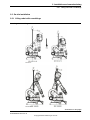
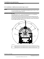
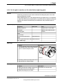
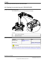
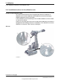
How to read the product manual
Reading the procedures
The procedures contain references to figures, tools, material, and so on. The
references are read as described below.
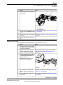
References to figures
The procedures often include references to components or attachment points
located on the manipulator/controller. The components or attachment points are
marked with italic text in the procedures and completed with a reference to the
figure where the current component or attachment point is shown.
The denomination in the procedure for the component or attachment point
corresponds to the denomination in the referenced figure.
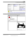
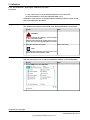
The table below shows an example of a reference to a figure from a step in a
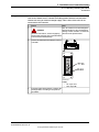
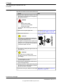
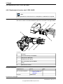
procedure.
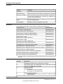
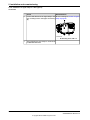
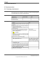
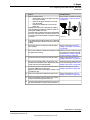
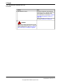
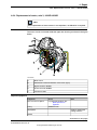
Note/IllustrationAction
Shown in the figure Location of
gearbox on page xx.
Remove the rear attachment screws, gearbox.8.
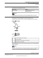
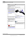
References to required equipment
The procedures often include references to equipment (spare parts, tools, etc.)
required for the different actions in the procedure. The equipment is marked with
italic text in the procedures and completed with a reference to the section where
the equipment is listed with further information, that is article number and
dimensions.
The designation in the procedure for the component or attachment point
corresponds to the designation in the referenced list.
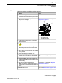
The table below shows an example of a reference to a list of required equipment
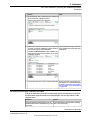
from a step in a procedure.
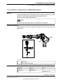
Note/IllustrationAction
Art. no. is specified in Required
equipment on page xx.
Fit a new sealing, axis 2 to the gearbox.3.
Safety information
The manual includes a separate safety chapter that must be read through before
proceeding with any service or installation procedures. All procedures also include
specific safety information when dangerous steps are to be performed.
Read more in the chapter Safety on page 19.
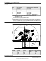
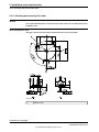
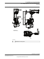
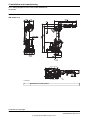
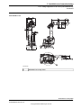
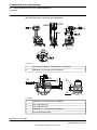
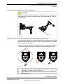
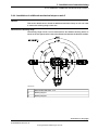
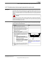
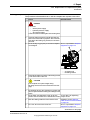
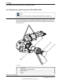
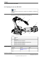
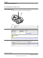
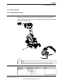
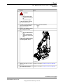
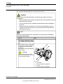
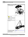
Illustrations
The robot is illustrated with general figures that does not take painting or protection
type in consideration.
Likewise, certain work methods or general information that is valid for several robot
models, can be illustrated with illustrations that show a different robot model than
the one that is described in the current manual.
Product manual - IRB 1600/1660 17
3HAC026660-001 Revision: W
© Copyright 2006-2018 ABB. All rights reserved.
How to read the product manual

This page is intentionally left blank

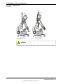
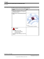
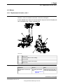
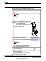
1 Safety
1.1 General safety information
1.1.1 Limitation of liability
Limitation of liability
Any information given in this manual regarding safety must not be construed as a
warranty by ABB that the industrial robot will not cause injury or damage even if
all safety instructions are complied with.
The information does not cover how to design, install and operate a complete
system, nor does it cover all peripheral equipment that can influence the safety of
the entire system.
In particular, liability cannot be accepted if injury/damage has been caused for any
of the following reasons:
• Use of the robot in other ways than intended.
• Incorrect operation or maintenance.
• Operation of the robot when the safety devices are defective, not in their
intended location or in any other way not working.
• When instructions for operation and maintenance are not followed.
• Non-authorized design modifications made in or around the robot.
• Repairs carried out by in-experienced or non-qualified personnel.
• Foreign objects.
• Force majeure.
Nation/region specific regulations
To protect personnel, the complete system must be designed and installed in
accordance with the safety requirements set forth in the standards and regulations
of the country where the robot is installed.
To be observed by the supplier of the complete system
The integrator is responsible that the safety devices necessary to protect people
working with the robot system are designed and installed correctly.
When integrating the robot with external devices and machines:
• The supplier of the complete system must ensure that all circuits used in the
safety function are interlocked in accordance with the applicable standards
for that function.
• The supplier of the complete system must ensure that all circuits used in the
emergency stop function are interlocked in a safe manner, in accordance
with the applicable standards for the emergency stop function.
Continues on next page
Product manual - IRB 1600/1660 19
3HAC026660-001 Revision: W
© Copyright 2006-2018 ABB. All rights reserved.
1 Safety
1.1.1 Limitation of liability

The integrator of the final application is required to perform an assessment of the
hazards and risks (HRA).
Note
The integrator is responsible for the safety of the final application.
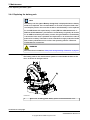
Safe access
The robot system shall be designed to allow safe access to all areas where
intervention is necessary during operation, adjustment, and maintenance.
Where it is necessary to perform tasks within the safeguarded space there shall
be safe and adequate access to the task locations.
Safety zones, which must be crossed before admittance, must be set up in front
of the robot's working space. Light beams or sensitive mats are suitable devices.
Turntables or the like should be used to keep the operator out of the robot's working
space.
A safety fence is recommended to ensure safeguarded space. Sufficient space
must be provided around the manipulator to protect those working with or on it
from hazards such as crushing.
The fence or enclosure must be dimensioned to withstand the force created if the
load being handled by the robot is dropped or released at maximum speed.
Determine the maximum speed from the maximum velocities of the robot axes and
from the position at which the robot is working in the work cell (see the section
Robot motion in the Product specification).
Also consider the maximum possible impact caused by a breaking or malfunctioning
rotating tool or other device fitted to the robot.
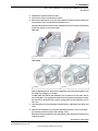
Safe handling
Users shall not be exposed to hazards, including slipping, tripping, and falling
hazards.
It must be possible to safely turn off tools, such as milling cutters, etc. Make sure
that guards remain closed until the cutters stop rotating.
It should be possible to release parts by manual operation (valves).
Safe design
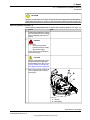
Emergency stop buttons must be positioned in easily accessible places so that
the robot can be stopped quickly. If any of the buttons do not stop all the robot
workcell motion, each emergency stop button must be marked, if more than one
is provided, to indicate its designated safety function.
Grippers/end effectors must be designed so that they do not drop work pieces/tools
in the event of a power failure or a disturbance to the controller.
Unauthorized modifications of the originally delivered robot are prohibited. Without
the consent of ABB, it is forbidden to attach additional parts through welding,
riveting, or drilling of new holes into the castings. The strength of the robot could
be affected.
20 Product manual - IRB 1600/1660
3HAC026660-001 Revision: W
© Copyright 2006-2018 ABB. All rights reserved.
1 Safety
1.1.1 Limitation of liability
Continued
Page is loading ...
Page is loading ...
Page is loading ...
Page is loading ...
Page is loading ...
Page is loading ...
Page is loading ...
Page is loading ...
Page is loading ...
Page is loading ...
Page is loading ...
Page is loading ...
Page is loading ...
Page is loading ...
Page is loading ...
Page is loading ...
Page is loading ...
Page is loading ...
Page is loading ...
Page is loading ...
Page is loading ...
Page is loading ...
Page is loading ...
Page is loading ...
Page is loading ...
Page is loading ...
Page is loading ...
Page is loading ...
Page is loading ...
Page is loading ...
Page is loading ...
Page is loading ...
Page is loading ...
Page is loading ...
Page is loading ...
Page is loading ...
Page is loading ...
Page is loading ...
Page is loading ...
Page is loading ...
Page is loading ...
Page is loading ...
Page is loading ...
Page is loading ...
Page is loading ...
Page is loading ...
Page is loading ...
Page is loading ...
Page is loading ...
Page is loading ...
Page is loading ...
Page is loading ...
Page is loading ...
Page is loading ...
Page is loading ...
Page is loading ...
Page is loading ...
Page is loading ...
Page is loading ...
Page is loading ...
Page is loading ...
Page is loading ...
Page is loading ...
Page is loading ...
Page is loading ...
Page is loading ...
Page is loading ...
Page is loading ...
Page is loading ...
Page is loading ...
Page is loading ...
Page is loading ...
Page is loading ...
Page is loading ...
Page is loading ...
Page is loading ...
Page is loading ...
Page is loading ...
Page is loading ...
Page is loading ...
Page is loading ...
Page is loading ...
Page is loading ...
Page is loading ...
Page is loading ...
Page is loading ...
Page is loading ...
Page is loading ...
Page is loading ...
Page is loading ...
Page is loading ...
Page is loading ...
Page is loading ...
Page is loading ...
Page is loading ...
Page is loading ...
Page is loading ...
Page is loading ...
Page is loading ...
Page is loading ...
Page is loading ...
Page is loading ...
Page is loading ...
Page is loading ...
Page is loading ...
Page is loading ...
Page is loading ...
Page is loading ...
Page is loading ...
Page is loading ...
Page is loading ...
Page is loading ...
Page is loading ...
Page is loading ...
Page is loading ...
Page is loading ...
Page is loading ...
Page is loading ...
Page is loading ...
Page is loading ...
Page is loading ...
Page is loading ...
Page is loading ...
Page is loading ...
Page is loading ...
Page is loading ...
Page is loading ...
Page is loading ...
Page is loading ...
Page is loading ...
Page is loading ...
Page is loading ...
Page is loading ...
Page is loading ...
Page is loading ...
Page is loading ...
Page is loading ...
Page is loading ...
Page is loading ...
Page is loading ...
Page is loading ...
Page is loading ...
Page is loading ...
Page is loading ...
Page is loading ...
Page is loading ...
Page is loading ...
Page is loading ...
Page is loading ...
Page is loading ...
Page is loading ...
Page is loading ...
Page is loading ...
Page is loading ...
Page is loading ...
Page is loading ...
Page is loading ...
Page is loading ...
Page is loading ...
Page is loading ...
Page is loading ...
Page is loading ...
Page is loading ...
Page is loading ...
Page is loading ...
Page is loading ...
Page is loading ...
Page is loading ...
Page is loading ...
Page is loading ...
Page is loading ...
Page is loading ...
Page is loading ...
Page is loading ...
Page is loading ...
Page is loading ...
Page is loading ...
Page is loading ...
Page is loading ...
Page is loading ...
Page is loading ...
Page is loading ...
Page is loading ...
Page is loading ...
Page is loading ...
Page is loading ...
Page is loading ...
Page is loading ...
Page is loading ...
Page is loading ...
Page is loading ...
Page is loading ...
Page is loading ...
Page is loading ...
Page is loading ...
Page is loading ...
Page is loading ...
Page is loading ...
Page is loading ...
Page is loading ...
Page is loading ...
Page is loading ...
Page is loading ...
Page is loading ...
Page is loading ...
Page is loading ...
Page is loading ...
Page is loading ...
Page is loading ...
Page is loading ...
Page is loading ...
Page is loading ...
Page is loading ...
Page is loading ...
Page is loading ...
Page is loading ...
Page is loading ...
Page is loading ...
Page is loading ...
Page is loading ...
Page is loading ...
Page is loading ...
Page is loading ...
Page is loading ...
Page is loading ...
Page is loading ...
Page is loading ...
Page is loading ...
Page is loading ...
Page is loading ...
Page is loading ...
Page is loading ...
Page is loading ...
Page is loading ...
Page is loading ...
Page is loading ...
Page is loading ...
Page is loading ...
Page is loading ...
Page is loading ...
Page is loading ...
Page is loading ...
Page is loading ...
Page is loading ...
Page is loading ...
Page is loading ...
Page is loading ...
Page is loading ...
Page is loading ...
Page is loading ...
Page is loading ...
Page is loading ...
Page is loading ...
Page is loading ...
Page is loading ...
Page is loading ...
Page is loading ...
Page is loading ...
Page is loading ...
Page is loading ...
Page is loading ...
Page is loading ...
Page is loading ...
Page is loading ...
Page is loading ...
Page is loading ...
Page is loading ...
Page is loading ...
Page is loading ...
Page is loading ...
Page is loading ...
Page is loading ...
Page is loading ...
Page is loading ...
Page is loading ...
Page is loading ...
Page is loading ...
Page is loading ...
Page is loading ...
Page is loading ...
Page is loading ...
Page is loading ...
Page is loading ...
Page is loading ...
Page is loading ...
Page is loading ...
Page is loading ...
Page is loading ...
Page is loading ...
Page is loading ...
Page is loading ...
Page is loading ...
Page is loading ...
Page is loading ...
Page is loading ...
Page is loading ...
Page is loading ...
Page is loading ...
Page is loading ...
Page is loading ...
Page is loading ...
Page is loading ...
Page is loading ...
Page is loading ...
Page is loading ...
Page is loading ...
Page is loading ...
Page is loading ...
Page is loading ...
Page is loading ...
Page is loading ...
Page is loading ...
Page is loading ...
Page is loading ...
Page is loading ...
Page is loading ...
Page is loading ...
Page is loading ...
Page is loading ...
Page is loading ...
Page is loading ...
Page is loading ...
Page is loading ...
Page is loading ...
Page is loading ...
Page is loading ...
Page is loading ...
Page is loading ...
Page is loading ...
Page is loading ...
Page is loading ...
Page is loading ...
Page is loading ...
Page is loading ...
Page is loading ...
Page is loading ...
Page is loading ...
Page is loading ...
Page is loading ...
Page is loading ...
Page is loading ...
Page is loading ...
Page is loading ...
Page is loading ...
Page is loading ...
Page is loading ...
Page is loading ...
Page is loading ...
Page is loading ...
Page is loading ...
Page is loading ...
Page is loading ...
Page is loading ...
Page is loading ...
Page is loading ...
Page is loading ...
Page is loading ...
Page is loading ...
Page is loading ...
Page is loading ...
Page is loading ...
Page is loading ...
Page is loading ...
Page is loading ...
Page is loading ...
Page is loading ...
Page is loading ...
Page is loading ...
Page is loading ...
Page is loading ...
Page is loading ...
Page is loading ...
Page is loading ...
Page is loading ...
Page is loading ...
Page is loading ...
Page is loading ...
Page is loading ...
-
 1
1
-
 2
2
-
 3
3
-
 4
4
-
 5
5
-
 6
6
-
 7
7
-
 8
8
-
 9
9
-
 10
10
-
 11
11
-
 12
12
-
 13
13
-
 14
14
-
 15
15
-
 16
16
-
 17
17
-
 18
18
-
 19
19
-
 20
20
-
 21
21
-
 22
22
-
 23
23
-
 24
24
-
 25
25
-
 26
26
-
 27
27
-
 28
28
-
 29
29
-
 30
30
-
 31
31
-
 32
32
-
 33
33
-
 34
34
-
 35
35
-
 36
36
-
 37
37
-
 38
38
-
 39
39
-
 40
40
-
 41
41
-
 42
42
-
 43
43
-
 44
44
-
 45
45
-
 46
46
-
 47
47
-
 48
48
-
 49
49
-
 50
50
-
 51
51
-
 52
52
-
 53
53
-
 54
54
-
 55
55
-
 56
56
-
 57
57
-
 58
58
-
 59
59
-
 60
60
-
 61
61
-
 62
62
-
 63
63
-
 64
64
-
 65
65
-
 66
66
-
 67
67
-
 68
68
-
 69
69
-
 70
70
-
 71
71
-
 72
72
-
 73
73
-
 74
74
-
 75
75
-
 76
76
-
 77
77
-
 78
78
-
 79
79
-
 80
80
-
 81
81
-
 82
82
-
 83
83
-
 84
84
-
 85
85
-
 86
86
-
 87
87
-
 88
88
-
 89
89
-
 90
90
-
 91
91
-
 92
92
-
 93
93
-
 94
94
-
 95
95
-
 96
96
-
 97
97
-
 98
98
-
 99
99
-
 100
100
-
 101
101
-
 102
102
-
 103
103
-
 104
104
-
 105
105
-
 106
106
-
 107
107
-
 108
108
-
 109
109
-
 110
110
-
 111
111
-
 112
112
-
 113
113
-
 114
114
-
 115
115
-
 116
116
-
 117
117
-
 118
118
-
 119
119
-
 120
120
-
 121
121
-
 122
122
-
 123
123
-
 124
124
-
 125
125
-
 126
126
-
 127
127
-
 128
128
-
 129
129
-
 130
130
-
 131
131
-
 132
132
-
 133
133
-
 134
134
-
 135
135
-
 136
136
-
 137
137
-
 138
138
-
 139
139
-
 140
140
-
 141
141
-
 142
142
-
 143
143
-
 144
144
-
 145
145
-
 146
146
-
 147
147
-
 148
148
-
 149
149
-
 150
150
-
 151
151
-
 152
152
-
 153
153
-
 154
154
-
 155
155
-
 156
156
-
 157
157
-
 158
158
-
 159
159
-
 160
160
-
 161
161
-
 162
162
-
 163
163
-
 164
164
-
 165
165
-
 166
166
-
 167
167
-
 168
168
-
 169
169
-
 170
170
-
 171
171
-
 172
172
-
 173
173
-
 174
174
-
 175
175
-
 176
176
-
 177
177
-
 178
178
-
 179
179
-
 180
180
-
 181
181
-
 182
182
-
 183
183
-
 184
184
-
 185
185
-
 186
186
-
 187
187
-
 188
188
-
 189
189
-
 190
190
-
 191
191
-
 192
192
-
 193
193
-
 194
194
-
 195
195
-
 196
196
-
 197
197
-
 198
198
-
 199
199
-
 200
200
-
 201
201
-
 202
202
-
 203
203
-
 204
204
-
 205
205
-
 206
206
-
 207
207
-
 208
208
-
 209
209
-
 210
210
-
 211
211
-
 212
212
-
 213
213
-
 214
214
-
 215
215
-
 216
216
-
 217
217
-
 218
218
-
 219
219
-
 220
220
-
 221
221
-
 222
222
-
 223
223
-
 224
224
-
 225
225
-
 226
226
-
 227
227
-
 228
228
-
 229
229
-
 230
230
-
 231
231
-
 232
232
-
 233
233
-
 234
234
-
 235
235
-
 236
236
-
 237
237
-
 238
238
-
 239
239
-
 240
240
-
 241
241
-
 242
242
-
 243
243
-
 244
244
-
 245
245
-
 246
246
-
 247
247
-
 248
248
-
 249
249
-
 250
250
-
 251
251
-
 252
252
-
 253
253
-
 254
254
-
 255
255
-
 256
256
-
 257
257
-
 258
258
-
 259
259
-
 260
260
-
 261
261
-
 262
262
-
 263
263
-
 264
264
-
 265
265
-
 266
266
-
 267
267
-
 268
268
-
 269
269
-
 270
270
-
 271
271
-
 272
272
-
 273
273
-
 274
274
-
 275
275
-
 276
276
-
 277
277
-
 278
278
-
 279
279
-
 280
280
-
 281
281
-
 282
282
-
 283
283
-
 284
284
-
 285
285
-
 286
286
-
 287
287
-
 288
288
-
 289
289
-
 290
290
-
 291
291
-
 292
292
-
 293
293
-
 294
294
-
 295
295
-
 296
296
-
 297
297
-
 298
298
-
 299
299
-
 300
300
-
 301
301
-
 302
302
-
 303
303
-
 304
304
-
 305
305
-
 306
306
-
 307
307
-
 308
308
-
 309
309
-
 310
310
-
 311
311
-
 312
312
-
 313
313
-
 314
314
-
 315
315
-
 316
316
-
 317
317
-
 318
318
-
 319
319
-
 320
320
-
 321
321
-
 322
322
-
 323
323
-
 324
324
-
 325
325
-
 326
326
-
 327
327
-
 328
328
-
 329
329
-
 330
330
-
 331
331
-
 332
332
-
 333
333
-
 334
334
-
 335
335
-
 336
336
-
 337
337
-
 338
338
-
 339
339
-
 340
340
-
 341
341
-
 342
342
-
 343
343
-
 344
344
-
 345
345
-
 346
346
-
 347
347
-
 348
348
-
 349
349
-
 350
350
-
 351
351
-
 352
352
-
 353
353
-
 354
354
-
 355
355
-
 356
356
-
 357
357
-
 358
358
-
 359
359
-
 360
360
-
 361
361
-
 362
362
-
 363
363
-
 364
364
-
 365
365
-
 366
366
-
 367
367
-
 368
368
-
 369
369
-
 370
370
-
 371
371
-
 372
372
-
 373
373
-
 374
374
-
 375
375
-
 376
376
-
 377
377
-
 378
378
-
 379
379
-
 380
380
-
 381
381
-
 382
382
-
 383
383
-
 384
384
-
 385
385
-
 386
386
-
 387
387
-
 388
388
-
 389
389
-
 390
390
-
 391
391
-
 392
392
-
 393
393
-
 394
394
-
 395
395
-
 396
396
-
 397
397
-
 398
398


Ask a question and I''ll find the answer in the document
Finding information in a document is now easier with AI
Related papers
-
ABB IRB 1600ID User manual
-
-
ABB IRC5 with FlexPendant Operating instructions
-
-
-
ABB IRC5 Compact Operating instructions
-
-
-
-
Other documents
-
 Generic unbranded 0815500240 Operating instructions
-
Omron Washdown Delta Robots IP67 - R6Y3 Series Technical Owner's manual
-
Howard Miller 495811 User manual
-
-
-
 Lovely Home ESSENTIALS Quartz Pendulum Wall Clock User manual
-
-
-
Hyundai HI4 User manual
-
Kawasaki KJ 314 Installation And Connection Manual

