MS-RA210 Installation Instructions
Important Safety Information
WARNING
Failure to follow these warnings and cautions could result in
personal injury, damage to the vessel, or poor product
performance.
See the Important Safety and Product Information guide in the
product box for product warnings and other important
information.
This device must be installed according to these instructions.
Disconnect the vessel's power supply before beginning to install
this product.
Before applying power to this product, make sure it has been
correctly grounded, following the instructions in the guide.
CAUTION
Always wear safety goggles, ear protection, and a dust mask
when drilling, cutting, or sanding.
NOTICE
When drilling or cutting, always check what is on the opposite
side of the surface.
You must read all installation instructions before beginning the
installation. If you experience difficulty during the installation,
contact FUSION
®
Product Support.
What's In the Box
• Mounting gasket
• Four 6-gauge, self-tapping screws
• Two screw covers
• Power and speaker wiring harness
• Auxiliary-in, line-out, and subwoofer-out wiring harnesses
Tools Needed
• Phillips screwdriver
• Electric drill
• Drill bit (size varies based on surface material and screws
used)
• Rotary cutting tool or jigsaw
• Silicone-based marine sealant (optional)
Mounting Considerations
• You must mount the stereo on a flat surface that provides
open airflow around the rear of the stereo for heat ventilation.
• If you are installing the stereo in a location that may be
exposed to water, you must mount it within 45 degrees of the
horizontal plane.
• If you are installing the stereo in a location that may be
exposed to water, add a drip loop to the cable to allow water
to drip off of the cable and avoid damage to the stereo.
• If you need to mount the stereo outside a boat, you must
mount it in a location far above the waterline, where it is not
submerged, and where it cannot be damaged by docks,
pilings, or other pieces of equipment.
• To avoid interference with a magnetic compass, you must
install the stereo at least 15 cm (5.9 in.) away from a
compass.
Mounting the Stereo
NOTICE
Do not use the stereo as a template when drilling the mounting
holes because this may damage the glass display and void the
warranty. You must only use the included template to correctly
drill the mounting holes.
Be careful when cutting the hole to mount the stereo. There is
only a small amount of clearance between the case and the
mounting holes, and cutting the hole too large could
compromise the stability of the stereo after it is mounted.
Do not apply grease or lubricant to the screws when fastening
the stereo to the mounting surface. Grease or other lubricants
can cause damage to the stereo housing.
Before you can mount the stereo in a new location on the
mounting surface, you must select a location in accordance with
the mounting considerations.
1
Adhere the template to the mounting surface.
2
Drill a hole inside the corner of the dashed line on the
template.
3
Cut the mounting surface along the inside of the dashed
line on the template.
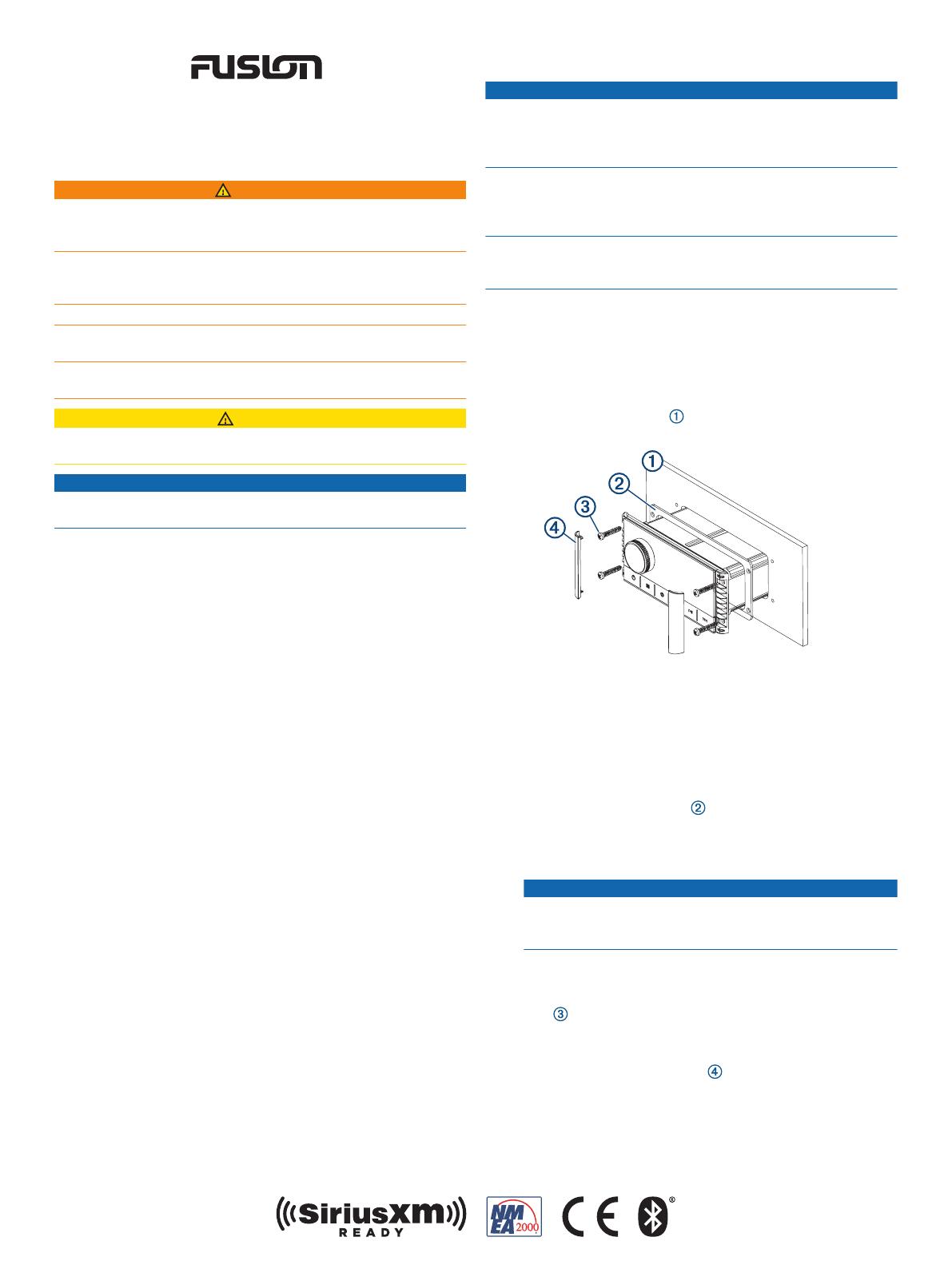
4
Ensure the mounting holes on the stereo line up with the pilot
holes on the template.
5
Using an appropriately sized drill bit for the mounting surface
and screw type, drill the pilot holes.
6
Remove the template from the mounting surface.
7
Complete an action:
• If you are installing the stereo in a dry location, place the
included mounting gasket on the back of the stereo.
• If you are installing the stereo in a location that is exposed
to water, apply silicone-based marine sealant on the
mounting surface around the cutout.
NOTICE
Do not install the included mounting gasket if you applied
sealant to the mounting surface. Using sealant and the
mounting gasket may reduce water resistance.
8
If you will not have access to the back of the stereo after
installation, make the necessary wiring connections.
9
Secure the stereo to the mounting surface using the included
screws .
You should hand-tighten the screws when securing the
stereo to the mounting surface to avoid over tightening them.
10
Snap the screw covers in place .
Connection Considerations
The stereo must be connected to power, either through the boat
ignition or an external switch, speakers, and media input
sources to function correctly. You should carefully plan the
October 2019
190-02629-91_0A


