ESAB Origo™Cut 36i User manual
- Category
- Welding System
- Type
- User manual
This manual is also suitable for


1 DIREC TIV E.... ...... ... ...... ..... ... ...... ...... .. ...... ...... ...... .. ...... ....2
2 SA FETY.............................................................................2
3 INTRODUCTION ............ ...... ........... ............ ............ ........4
3.1 Equip ment. ..... ..... .. ..... ..... ..... .. ..... ..... ..... ..... .. ..... ...4
4 TECHNICAL DATA.........................................................5
5 INSTALLATION.... ........ ........ ......... .... ........ ........ ........ .... ..5
5.1 Mains and Workpiece Connection.................6
6 OPERATION.. .... ... ..... .... ..... .. ..... ..... .. ..... ..... ..... .. ..... ..... .... .7
6.1 Connection and Control Devices...................8
377RUFKDQG³;7´&RQVXPDEOHV
6.3 Cuttin g with PT - 31 XL... ... ... .............................9
6.4 Common Cutting Problems. ..... ..... ................10
7 MAINTENANCE.................. ...... .............. .............. .........11
7.1 Check-up and Cleaning....... ... ... ............ .........11
8 FAULT-TRACKING/TROUBLESHOOTING..............12
8.1 Troubleshooting guide....................................12
8.2 Sequence of op era tion....... ........... ........... ......16
9 ORDERING SPARE PARTS......... ... .......................... ...17
9.1 Detail pictures............ ........... ........... ...... ........... .17
9.2 Spare Part List............................................ ........18
10 A CCESSOR IES.... ................ ............... ....... ................ ..18
DIA GRAM.............................................................................19
1
TABLE OF CONTENTS
GB
INSTRUC TION MA NU AL
PLASMA ARC CUTTING PACKAGES

1 DIRECTIVE
2 SAFETY
Users of ESAB welding equipment have the ultimate responsibility for ensuring that anyone w ho
works on or near the equipment observes all the relevant safety precautions. Safety precautions
must meet the requirements that apply to this ty pe of plasma cutting equipment. The following
recommendations should be observed in addition to the standard regulations that apply to the
workplace.
All work must be carried out by trained personnel well-acquainted with the operation of the plasma
cutting equipment. Incorrect operation of the equipment may lead to hazardous situations which
can result in injury to the operator and damage to the equipment.
1. Anyone who uses the plasma cutting equipment must be familiar with:
- its operation
- location of emergency stops
- its function
- relevant safety precautions
- plasma cutting
2. The operator must ensure that:
- no unauthorized person is stationed within the working area of the equipment when it is
started up
- no one is unprotected when the arc is struck
3. The workplace must:
- be suitable for the purpose
- be free from draughts
4. Personal safety equipment
- always wear recommended personal safety equipment, such as safety glasses, flame-
proof clothing, safety gloves
5. General precautions
- make sure the return cable is connected securely
- work on high voltage equipment may only be carried by a qualified electrician
- appropriate fire extinguishing equipment must be clearly marked and close at hand
- Lubrication and maintenance must not be carried out on the equipment during operation.
DECLARATION OF CONFORMITY
ESAB Welding Equipment AB, S-695 81 Laxå, Sweden, declares that plasma cutting equipment Orig oCut-36i f rom
serial Nr. 604
onwards conforms to standard IEC/EN 60974-1, IEC/EN 60974-10, in accordance with the requirement
of directive (73/23/EEC) and appendix (93/68/EEC) and standard EN 60974-10 in accordance with the requirements
of directive (89/336/EEC) and appendix (93/68/EEC).
Laxå, 01-03-2006
HENRY SELENIUS
Vice President
ESAB Welding Equipment AB
695 81 Laxå Tel: +46-584-81000 Fax: +46-584-411924
SWEDEN
2
GB
INSTRUC TION MA NU AL

Note! This product is solely intended for plasma cutting
3
A RC WELDING A ND CUTTING CA N BE INJURIOUS TO YOURSELF A ND OTHERS. TAKE PRECA UTIONS WHEN
:(/',1*$1'&877,1*$6.)25<285(03/2<(5¶66$)(7<35$&7,&(6:+,&+6+28/'%(%$6('21
0$18)$&785(5¶6+$=$5''$7$
ELECTRIC SHOCK - Can kill
- Install and earth the welding/cutting unit in accordance wi th appli ca ble standards.
- Do not touch li v e electri cal parts or electrodes with bare skin, wet gloves or w et clothing.
- Insulate yourself from earth and the workpiece.
- Ensure your working stance is safe.
FUMES AND GASES - Can be dangerous to health
- Keep your he ad out of the fu m es.
- Use ventilation, extraction at the arc, or both, to take fumes and gases away from your
breathing zone and the general area.
ARC RAYS - Can injure eyes and burn skin.
- Protect your eyes and body. Use the correct welding/cutting screen and fi lter len s and
wear protective clothing.
- Protect bystanders with suitable screens and courtains.
FIRE HA ZARD
- Sparks (spatter) can cause fire. Make sure therefore that there are no i nflammable materials
nearby.
NOISE - Excessive noice can damage hearing.
- Pro t ec t yo ur ears . Use earmu f fs or ot h er hear i n g prot e ct ion.
- Warn bystanders of the risk.
MALFUNCTION - Call for expert assistance in the event of malfunction.
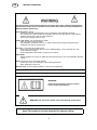
READ AN D UNDERSTAND THE INSTRUCTION MANUA L BEFO RE INSTALLING OR OPERATING
PRO TE CT YOURSE L F A N D OTHERS!
WARNING!
Read and understand the instruction manual
before installing and operating
WARNING! Do not use t he power source for thawing frozen pipes.
GB
INSTRUC TION MA NU AL

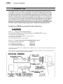
The Ori goCut- 36i is a compact, completely self-contained plasma cutting system.
As shippe d, the syst em is fully assem bled and ready to cut after being conne cted
to input power and a source of prefiltered compressed air 5-10 bar (torch setted
at 118 lt/min @ 5.2 bar). The OrigoCut-36i package uses the PT-31XL torch with
35 Amp consumables to deliver cutting power for materials up to 9 mm thick or
for severing up to 12 mm thick. Refer to the following para graphs for desc r i ptions
of the OrigoCut-36i packages available as well as performance specifications.
Do not use any torch with this power source other than the ESAB brand
PT-31XL torch. Serious injury may occur if used with any other torch.
6HHEHORZIRU(6$%¶VDFFHVVRULHVIRUWKHFXWWLQJWRUFK
3 INTRODUCTION
3.1 Equipment
List 3.1.1 OrigoCut-36i Cutting Packages
Each
OrigoCut-36i Plasma Arc Cutting Package P/N 0558007873 includes:
N°1 Power Source
OrigoCut-36i.
N°1 PT-31XL* Torch assembly with 4,5 m service lines.
N°1 earth cable 5 m length.
N°1 Torch Spare Parts Kit , see list below.
List 3.1.2 PT-31XL* Spare Parts Kit P/N 0558003462 Contents
N° 3 35/40A Nozzle, P/N (21008) 0558000508
N° 2 Electrode, P/N (20862) 0558000507
N° 1 Swirl Baffle, P/N (20463) 0558000506
N° 1 Long Heat Shield, P/N (36284) 0558000509
*PT-31XL Torch Assembly P/N 0558001466 is supplied with the nozzle, electrode, swirl baffle and heat
shield assemb led.
(Part numbers in brackets could be found on the explosion drawings inside the torch spare part kit box.)
4
Fig. 3.1.2 PT - 31 spare part list and consumables
GB
INSTRUC TION MA NU AL

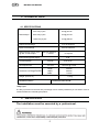
4 TECHNICA L DATA
4.1 SPECIFICATIONS
35% Duty Cycle* 35A @ 94V dc
Rated Output 60% Duty Cycle* 27A @ 91V dc
100% Duty Cycle* 21A @ 88V dc
Output Current Range 15 to 35 Amperes
Open Circuit Voltage 270 V dc Nominal
Rated Primary Input Imax 230 Vac 50/60 Hz,
@ 35A 94 Vdc Output 1- Phase 17 Ampere
Power factor @ 35 A Output 0,99
Current Capacity PT-31XL 35 A dc SP
Air Requirements PT-31 XL 118 lt/min @ 5.2 bar
Length 350 mm
Dimensions of
OrigoCut-36i Height 290 mm
Width 170 mm
W eight (less torch) 9,5 kg
Insulation class: F Protection class: IP 23S
*DutyCycle
The duty cycle refers to the time as a percentage of a ten-minute period that you can weld or cut at a
certain load without overloading the product.
5 INSTALLATION
The installation must be executed by a professional.
5
GB
INSTRUC TION MA NU AL

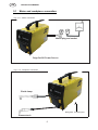
5.1 Mains and workpiece connection
Mains plug and socket
OrigoCut-36i Power Source
6
Plasma torch
Fig. 5.1.1 - Mains connection
Fig. 5.1.2 - Workpiece connection
GB
INSTRUC TION MA NU AL
Earth clamp
Rating Plate on bottom panel

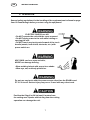
6 OPERATION
ELECTRIC SHOCK can kill.
'R127RSHUDWHWKHXQLWZLWKWKHFRYHUUHPRYHG
'R127DSSO\SRZHUWRWKHXQLWZKLOHKROGLQJRU
carrying the unit.
'R127WRXFKDQ\WRUFKSDUWVIRUZDUGRIWKHWRUFK
handle (nozzle, heat shield, electrode, etc.) with
power switch on.
ARC RAYS can burn eyes and skin;
NOISE can damage hearing.
:HDUZHOGLQJKHOPHWZLWKSURSHUOHQVVKDGH
:HDUH\HHDUDQGERG\SURWHFWLRQ
Position the OrigoCut-36i (at least) 3 meters from
the cutting area. Sparks and hot slag from the cutting
operation can damage the unit.
General safety regulations for the handling of the equipment can be found on page
2 and 3. Read through before you start using the equipment!
Do not use any torch with this power source other than the ESAB brand
PT-31 XL torch. Serious injury may occur if used with any other torch.
7
GB
INSTRUC TION MA NU AL

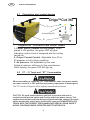
6.1 Connection and control devices
OrigoCut-36i CONTROLS and FRONT PANEL
1. Power Switch (located on rear panel). When
placed in ON position, the green LED will glow
indicating control circuit is energized and the cooling
fan will run.
2. Output Current Control. Adjustable from 20 to
35 amperes to suit cutting conditions.
3. Air pressure. Not adjustable by the user.
Setted at optimum efficiency by the manufacturer.
While flowing, the green LED will light up.
1
377RUFKDQG ³;7´&RQVXPDEOHV
:KHQDVVHPEOLQJRUUHSODFLQJ³;7´FRQVXPDEOHVPDNHVXUHSRZHUVZLWFK
on power source is in OFF position and primary input power is deenergized.
The PT-31 torch of OrigoCut-36i is originally assembled and tested.
The PT-31 XL torch head contains a gas flow check valve that acts in
conjuction with the flow switch and circuitry within the power source. This
system prevents the torch from being energized with high voltage if the torch
switch accidentally closed when the shield is removed. ALWAYS REPLACE
TORCH WITH THE PROPER TORCH MANUFACTURED BY ESAB SINCE IT
$/21(&217$,16(6$%¶63$7(17('6$)(7<,17(5/2&.
8
2
3
Overheating LED
GB
INSTRUC TION MA NU AL
Origo
TM
Cut 36i

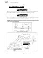
6.3 Cutting with PT - 31 torch
Wear the usual protective gloves, clothing and helmet. Helmet with filter lens
shade No. 6 or 7 should provide adequate protection for your eyes.
Never touch any parts forward of the torch handle (tip, heat shield, electrode,
etc.) unless the power switch is in the OFF position.
Caution: Do not depress the torch switch unless the torch nozzle i s touching or within
1 mm (1/32-in.)of the workpiece.
9
Tab. 6.3.1 Effect of cutting speed
TOO F AST TOO SLOW CORRECT
Tab. 6.3.2 Piercing Technique using PT - 31 XL
TO STARTA PIERCE,TILTTHE
TOR CH TO PREVENT MOLTEN
MATERIAL FROM COMIN G BACK
AGAINST AND DAMAGING THE
TORCH
WHEN THE AR C BREAKS
THROUGH THE WORK,
BRING THE TORCH TO AN
UPRIGHT POSITION AND
PRO CEED TO CUT.
GB
INSTRUC TION MA NU AL

6.4 COMMON CUTTING PROBLEMS
Listed below are common cutting problems followed by the probable cause of each.
If problems are determined to be caused by OrigoCut-36i, refer to the maintenance
section of this manual. If the problem is not corrected after referring to the maintenance
section, contact your ESAB representative.
A. Insufficient Penetration.
1. Cutting speed too fast.
2. Damag ed cutting nozzle.
3. Improper air pressure.
B. Main Arc Estinguishes.
Cutting speed too slow.
C. Dross Formation. (In some materials and thicknesses, it may be impossible to get
dross-free cuts)
1. Cutting speed too fast or too slow.
2. Improper air pressure.
3. Faulty nozzle or e lect rod e.
D. Double Arching. (Damaged nozzle orifice)
1. Low air pressure.
2. Damaged cutting nozzle
3. Loose cutting nozzle.
4. Heavy spatter.
E. Uneven Arc.
Damaged cutting noz zl e or worn electrode
F. Unstable Cutting Conditions.
1. Incorrect c utting speed.
2. Loose cable or hose connections.
3. Electrode and/or cutting nozzle in poor condition.
G. Main Arc Does Not Strike. (Loose connections)
H. Poor Consumable Life.
1. Improper gas pressure.
2. Contaminated air supply.
10
GB
INSTRUC TION MA NU AL

7 MAINTENANCE
Regular maintenance is important for safe, reliable operation.
Note:
All w arranty undertakings given by the supplier cease to apply if the customer attempts
to rectify any faults on the machine during the warranty period.
If this equipment does not operate properly, stop work immediately and investiga-
te the cause of the malfunction. Maintenance work must be performed by an
experienced person, and electrical work by a trained electrician. Do not permit
untrained persons to inspect, clean, or repair this equipment. Use only
recommended replacement parts.
Be sure that the wall disconnect switch or wall circuit breaker is open before
attempting any inspection or work inside of the OrigoCut-36i.
7.1 CHECK - UP AND CLEANING
Water or oil occasionally accumulates in compressed air lines. Be sure to direct
the first blast of air away from the equipment to avoid damage to OrigoCut-36i.
Frequent inspection and cleaning of the OrigoCut-36i is recommended for safety and
proper operation. Some suggestions for inspecting and cleaning are as follows:
A. Check work cable to work piece connection.
B. Check safety earth ground at work piece and at power source chassis.
C. Check heat shield on torch. It should be replaced if damaged.
D. Check the torch electrode and cutting nozzle for w ear on a daily basis. Remove
spatter or replace if necessary.
E. Make sure cable and hoses are not damaged or kinked.
F. Make sure all fittings and ground connections are tight.
11
GB
INSTRUC TION MA NU AL

8 FAULT-TRACING / TROUBLESHOOTING
Try these recommended checks and inspections before sending for an authorized
service technician.
ELECTRIC SHOCK CAN KILL! Be sure that all primary power to the machine has
been externally disconnected.Open the line (wall) disconnect switch or circuit
breaker before attempting inspection or work inside of the power source.
Check the problem against the symptoms in the following troubleshooting guide. The remedy may be
quite simple. If the cause cannot be quickly located, shut off the input power, open up the unit, and perform
a simple visual inspection of all the components and wiring. Check for secure terminal connections, loose
or burned wiring or components, bulged or leaking capacitors, or any other sign of damage or discoloration.
Those indications do not invalidate all other safety regulations and restrictions expressed in other sections
of this manual.
Voltages in plasma cutting equipment are high enough to cause serious injury or possibly death.
Be particularly careful around equipment when the covers are removed.
NOTE
Before checking voltages in the circuit, disconnect the power from the high frequency generator to avoid
damaging your voltmeter.
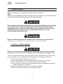
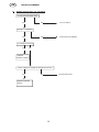
8.1 TROUBLESHOOTING GUIDE
Any remedy that requires an intervention inside the machine must be executed by
an authorized service center.
A. Difficult Starting.
Change electrode
Change nozzle
Check for good, clean connection of work lead to workpiece
Check air pressure (5 - 5,2 bar)
Check torch power cable for continuity
Depress torch switch. After 2 seconds, is high frequency present?
No
Yes
,VWKH³$LU´/('OLJKWRQ" Repair/replace control - HF PCB
Yes No
Repair/replace Repair/replace Control
power source control - HF PCB Flow Switch
12
GB
INSTRUC TION MA NU AL

B. No Air
Is air hose connected?
Yes No Conne ct
Is air adjusted to 4 - 5 bar ?
Yes No Adjust
Check torch integrity
Yes No 1RHOHFWURGHLQWRUFK
1RYDOYHSLQLQWRUFK
5HSODFHHOHFWURGH
Check continuity of torch switch 5HSODFH YDOYHSLQ
OK No Replace torch switch
Repair/replacepowersource
C. Air does not shut off
Does arc start when nozzle contacts work without depressing torch switch?
Yes No
Check for short in torch switch
Does air flow even when OrigoCut-36i power switch is OFF?
Yes No
Replace Repair/replace
solenoidvalve control - HF PCB
13
GB
INSTRUC TION MA NU AL

D. ON/OFF Switch light not energized.
Is main 230 volt switch ON?
Yes No Turn on switch
Is plug in receptacle?
Yes No Insert plug in receptacle
Is cooling fan turning?
Yes No
Replace
ON/OFF Switch
Check voltage at receptacle and input power line
Yes No Check main fuses
Replace ON/OFF
Switch
14
GB
INSTRUC TION MA NU AL

19
(front view) (rear view)
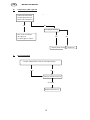
E. Temperature LED light ON.
Is the unit overheated?
("Fault" lights turns off
when Unit cools down.)
Yes No
Is cooling air flowing?
Duty cycle exceeded:
35% @ 35 A, Yes No
or 100% @ 21 A output
Repair power source Repair fan
F.
No current output
Is input voltage within ±10% of units input rating?
Yes No
See (D.) sequence above
Unsolved
Repair power source
15
GB
INSTRUC TION MA NU AL

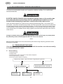
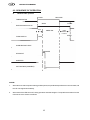
ENERGIZE
10 SEC
Postflow
OPEN
2SEC.
NOTES:
1. When the torch switch is pushed during postflow period ,the postflow and preflowtimes are canceled, and
the HF is energized immediately.
2. When the air flow LED comes off, cutting operation should be stopped. The postflow time starts from the
moment the torch switch is released.
TORCHSWITCH
OPEN CLOSE
GAS SOLENOID VALVE
PREFLOW
FLOW SWITCH CLOSE
OVERHEATING LIGHT
HFCIRCUI T
INVERTER
CUTTING ARC(CURRENT)
P USH RELEASE
16
GB
INSTRUC TION MA NU AL
8.2 SEQUENCE OF OPERATION
A. LOCK-IN "OFF" position

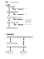
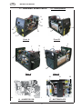
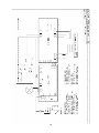
9 - ORDERING SPA R E PARTS 9.1 - Detail pictures
GB
INSTRUC TION MA NU AL
17
Front A
Front B
Rear A Rear B
13 - INVERTER PCB 17-BOTTOMPLATE
7
8
12
9
6
20
1918
4
rear front front rear
14
22
8
10
15
5
17
13
11
4
3
21
24
16

OrigoCut-36i is designed and tested in accordance with the international and
European standards IEC/EN 60974-1 and EN 60974-10.
It is the obligation of the service unit which has carried out the service or repair
work to make sure that the product s till conforms to the said standard.
Spare parts are ordered through your nearest ESAB representative, see back cover. When
ordering spare parts, please state machine type, and number as well as designation and
spare part number as shown in the spare part list.
This will simplify dispatch and ensure y ou get the right part. Nev ertheless, any replacement
of parts inside the machine must be executed by an authorized service center.
9.2 - Spare Part List
18
10 ACCESSORIES
For plasma torch PT - 31 accessories, please see section 3.1 Equipment, page 4.
GB
INSTRUC TION MA NU AL
ITEM NO. P ART NO. DESCRIPTION
1 0459173001 UPPERC ASE (L ID)
2 0459119001 HANDLE
3 0700156021 TRANSPARENT SWITCH COVER
4 0558008067 CONTROL /HF PCB
5 0700156023 HF GENE RATOR
6 0700156006 $,51,33/(´'LDPP/ PP
7 0700156007 POWER CABLE 3x1,5 sqmm, L=2,5 m
8 0558001466 PT - 31 XL TORCH Ass.ly
9 0700156008 PRESS URE GAUGE
10 0558008095 FAN
11 0700156010 EMC FILTER
12 0558000410 FLOW SWITCH P/N 951202
13 0558008066 IN VERTER PCB
14 0700156012 ON/OFF SWITCH
15 0700156013 EARTH CABLE W/CLAMP, L=5m
16 0459172001 P LASTIC FRONT PAN EL
17 0558008068 B OTT OM PLATE
18 0700156015 CHOKE (INDUCTANCE)
19 0558008096 TRANSFORMER
20 0700156017 HEAT SINK WITHDIODES
21 0700156024 VENTILATION GRID
22 0700156019 KNO B Dia. 25 mm
24 0700156020 SOLENOID VALVE
23 0558008097 Multilanguage user manual

19
Page is loading ...
-
 1
1
-
 2
2
-
 3
3
-
 4
4
-
 5
5
-
 6
6
-
 7
7
-
 8
8
-
 9
9
-
 10
10
-
 11
11
-
 12
12
-
 13
13
-
 14
14
-
 15
15
-
 16
16
-
 17
17
-
 18
18
-
 19
19
-
 20
20
-
 21
21


ESAB Origo™Cut 36i User manual
- Category
- Welding System
- Type
- User manual
- This manual is also suitable for
Ask a question and I''ll find the answer in the document
Finding information in a document is now easier with AI
Related papers
-
ESAB Powercut 700 User manual
-
ESAB Origo™ Cut 35i User manual
-
ESAB Origo™ Cut 36i User manual
-
-
-
ESAB Caddy®Cut User manual
-
-
-
-