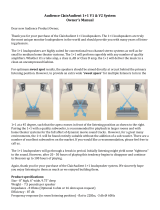
PRESONUS ULT10 Owner's manual

Category
Supplementary music equipment
Type
Owner's manual

This manual is also suitable for

ULT-series
Loudspeakers
Owners Manual
www.presonus.com
®
Français
Español
Deutsch
English
Table of Contents
1 Overview1
1.1 Introduction1
1.2 About This Manual1
1.3 Summary of ULT-Series Loudspeaker Features2
1.4 What is in the Box3
2 Getting Started4
2.1 Level Setting Procedure (Full-Range)4
2.2 Level Setting Procedure (ULT18)7
3 Hookup11
3.1 Rear-Panel Connections and Controls 11
3.2 Onboard Performance Monitoring13
3.3 Power13
3.4 Hookup diagrams14
4 Loudspeaker Placement and System Configuration15
4.1 Recognizing Problem Rooms15
4.2 System configuration suggestions17
4.3 Rigging and Safety 21
5 Technical Information24
5.1 Specifications24
5.2 Optional Accessories25
6 Troubleshooting and Warranty26
6.1 Support and Troubleshooting 26
6.2 Warranty27
1 Overview
1.1 Introduction
ULT-series
Owners Manual
1
1 Overview
1.1 Introduction
Thank you for purchasing a PreSonus® ULT-series Active Loudspeaker. PreSonus
Audio Electronics has designed ULT-series Loudspeakers utilizing high-grade
components to ensure optimum performance throughout the life of your PA
system. The ULT-series loudspeakers are active PA speaker systems that provide
the widest horizontal dispersion in their class, thanks to the custom Pivot X110
horn. Compact and lightweight, they provide a powerful, professional sound
that makes them an ideal solution for mobile and install solutions alike.
We encourage you to contact us with questions or comments regarding
this product. PreSonus Audio Electronics is committed to constant
product improvement, and we value your suggestions highly. We believe
the best way to achieve our goal of constant product improvement is by
listening to the real experts: our valued customers. We appreciate the
support you have shown us through the purchase of this product.
For technical support, please see Section 6.1: Troubleshooting.
1.2 About This Manual
This manual covers hardware features and functions for every full-range
ULT-series loudspeaker (ULT10, ULT12, and ULT15) as well as the companion
ULT18 subwoofer. We suggest that you use the manual to familiarize
yourself with the features, applications, and connection procedures for
your ULT-series loudspeakers before trying to set up and operate them.
Except for Low Frequency Driver configuration and some technical specifications
(such as weight, frequency response, and maximum SPL), the features and
functions of all three full-range models are the same. In many respects, the
functions of the ULT18 are also the same. Whenever possible these features and
functions will be described for the entire line. Unless preceded by “full-range”,
the term “loudspeaker will refer to every full-range model and the subwoofer.
Throughout this manual you will find Power User Tips highlighting
unique aspects of your ULT-series loudspeaker, as well as explanations of
various audio terms. In addition, you will find an assortment of tutorials
that cover the basics of room acoustics and speaker placement.
Thank you, once again, for buying our product. We are confident
that you will enjoy your ULT-series loudspeakers!
1 Overview
1.3 Summary of ULT-Series Loudspeaker Features
ULT-series
Owners Manual
2
1.3 Summary of ULT-Series Loudspeaker Features
1.3.1 Full-range Models (ULT10, ULT12, and ULT15)
10” / 12” / 15” Woofer with 2.5” Voice Coil
1.75” diaphragm compression driver
Worx designed waveguide Pivot X110 Horn for precise coverage
Ultrawide 110˚ horizontal dispersion
Tight 50˚ vertical dispersion for farther throw
3 presets plus high pass filter
Maximum SPL 130 / 135 / 136 dB peak
65 Hz / 55 Hz / 52 Hz to 20 kHz frequency response
Multi-angle enclosure for mains or monitor wedge application
1300-watt Class D power (150W x 500W continuous)
Onboard mixer with two combo XLR and ¼” inputs; direct line
input channel output; and single summed balanced output
Defeatable front-panel LED
Rugged, texture-painted eucalyptus enclosures
XMAX Preamp
Rotatable horn for horizontal mains use
Tour-grade 16 gauge steel grilles
Comfortable ergonomic handles
35 mm pole sockets with 6˚ downward tilt
M10 rigging points for suspended installation
Locking IEC connection
1.3.2 ULT18 Subwoofer
18” Woofer with 4” Voice Coil
7mm driver travel before over-excursion
Extended Bass preset
Polarity Invert
Onboard fully Variable Low Pass filter lets you dial in upper frequency limit
Maximum SPL 135 dB peak
35 Hz to 150 Hz (variable) frequency response
2000-watt Class D power (2 × 500W continuous)
Stereo Combo XLR and ¼” inputs with direct outputs
Mono Mode sums both inputs to both outputs
Defeatable front-panel LED
Rugged, texture-painted eucalyptus enclosures
Tour-grade 16 gauge steel grilles
Comfortable ergonomic handles
Locking IEC connection
1 Overview
1.4 What is in the Box
ULT-series
Owners Manual
3
1.4 What is in the Box
In addition to this manual, your ULT package contains the following:
(1) ULT10, ULT12, ULT15, or ULT18 Loudspeaker
(1) Locking IEC power cable
2 Getting Started
2.1 Level Setting Procedure (Full-Range)
ULT-series
Owners Manual
4
2 Getting Started
Before you begin, here are a few general rules of thumb:
Always make sure your loudspeakers are powered off when making connections.
Do not allow your inputs to clip. Watch the Clip LED on the back of your
loudspeaker. When this LED illuminates, it indicates that the analog-
to-digital converters are in danger of being overdriven. Overdriving
the converters will cause digital distortion, which sounds terrible.
Your full-range loudspeaker provides both attenuation and boost
for the line inputs. The center detent is the unity gain setting. This is
the recommended starting point for gain-staging your system.
Your PA and studio equipment should be powered on in the following order:
1. Sound sources (keyboards, direct boxes, microphones,
etc.) connected to your mixer
2. Mixer
3. ULT-series Loudspeakers
When it’s time to power down, your system should be turned off in the reverse order.
Now that you know what not to do, lets get some audio going! The following
level-setting tutorials cover best practices that can be applied to nearly every
application. The first tutorial covers level setting for the full-range models
only; the second tutorial describes proper level setting for a system that
includes one ULT18 subwoofer and two full-range ULT-series loudspeakers.
2.1 Level Setting Procedure (Full-Range)
1. With the power switch in the Off position, connect the locking IEC plug to
the IEC socket connection on the back of the loudspeaker and plug it into
a grounded AC outlet or surge protector.
WARNING: While a locking IEC cable is ideal for permanent installation,
be careful that this cable cannot be tripped over in ground-stacked
applications, as this is a toppling risk.
2. Turn the level knobs fully counterclockwise, to the lowest position.
100-230V~, 50-60 Hz, 150W
DIRECT OUT
MIX OUT
LINE
HPF DJ FOHMON SIGNAL CLIP TEMP
MIC/LINE
LINE LEVEL
MIC / LINE
MIC/LINE
-15 +65
M
I
C
L
I
N
E
LINE LEVEL
MIC / LINE
-15 +65
M
I
C
L
I
N
E
2 Getting Started
2.1 Level Setting Procedure (Full-Range)
ULT-series
Owners Manual
5
3. If youre using the ULT full-range loudspeaker as a mixer, connect
a microphone to the Mic input with a standard XLR cable.
4. Connect your line-level source (such as a PreSonus StudioLive
digital mixer) to the Line input. The Line input is a combo
connection that accepts a balanced ¼” TRS or XLR cable.
Power User Tip: If you are running a stereo system, connect the
Left output of your mixer to the Left loudspeaker’s line input, and
the Right output to the Right loudspeaker’s line input.
5. Power on your line-level source.
DIRECT OUT
MIX OUT
LINE
HPF DJ FOHMON SIGNAL CLIP TEMP
MIC/LINE
LINE LEVEL
MIC / LINE
-15 +65
M
I
C
L
I
N
E
DIRECT OUT
MIX OUT
LINE
HPF DJ FOHMON SIGNAL CLIP TEMP
MIC/LINE
LINE LEVEL
MIC / LINE
MIC/LINE
-15 +65
M
I
C
L
I
N
E
2 Getting Started
2.1 Level Setting Procedure (Full-Range)
ULT-series
Owners Manual
6
6. Power on your ULT-series loudspeaker.
7. While speaking into the microphone, use the Mic level knob to
adjust the microphone level. Be sure that you are not standing
directly in front of the loudspeaker while doing this, as doing so
could result in feedback. If you are not using the Mic input, it is
recommended that you leave this knob in the fully counter-clockwise
position so as not to introduce noise into your signal path.
8. With audio playing through your line-level source, turn the
Line level knob until you have achieved a comfortable listening
volume. If you are not using the Line input, it is recommended
that you leave this knob in the fully counterclockwise position
so as not to introduce noise into your signal path.
9. Both the Microphone and Line inputs should be set so that the
green Signal LED is illuminated most of the time, but the red Clip
LED illuminates only with the highest transient peaks or not at all.
10. If you are using the input mixer of one loudspeaker to
connect a microphone and a line-level source, or if you
are running a mono system, connect the Mix Out from the
loudspeaker to which your sources are connected to the line
input of the second loudspeaker and repeat steps 1-9.
POWER
On/O
100-230V~, 50-60 Hz, 150W
DIRECT OUT
MIX OUT
LINE
HPF DJ FOHMON SIGNAL CLIP TEMP
MIC/LINE
LINE LEVEL
MIC / LINE
-15 +65
M
I
C
L
I
N
E
LINE LEVEL
SIGNAL CLIP TEMP
SIGNAL CLIP TEMP
DIRECT OUT
MIX OUT
LINE
HPF DJ FOHMON SIGNAL CLIP TEMP
MIC/LINE
LINE LEVEL
MIC / LINE
MIC/LINE
-15 +65
M
I
C
L
I
N
E
DIRECT OUT
MIX OUT
LINE
HPF DJ FOHMON SIGNAL CLIP TEMP
MIC/LINE
LINE LEVEL
MIC / LINE
MIC/LINE
-15 +65
M
I
C
L
I
N
E
2 Getting Started
2.2 Level Setting Procedure (ULT18)
ULT-series
Owners Manual
7
2.2 Level Setting Procedure (ULT18)
1. With the power switch in the Off position, connect the locking IEC
plug to the IEC socket connection on the back of each loudspeaker
and plug it into a grounded AC outlet or surge protector.
2. Turn the level knobs on your full-range loudspeakers
fully counterclockwise to the lowest position.
3. Turn the Output level knob on your ULT18
counterclockwise to the lowest position.
4. Connect your line-level source (e.g., a StudioLive mixer) to the Line
inputs. This is a combo jack that accepts a balanced ¼” TRS or XLR plug.
If you are connecting a stereo source, the left side should be connected
to Input 1 and the right side should be connected to Input 2.
100-230V~, 50-60 Hz, 150W
DIRECT OUT
MIX OUT
LINE
HPF DJ FOHMON SIGNAL CLIP TEMP
MIC/LINE
LINE LEVEL
MIC / LINE
MIC/LINE
-15 +65
M
I
C
L
I
N
E
LINE LEVEL
MIC / LINE
-15 +65
M
I
C
L
I
N
E
LED o
MIC/LINE
SIGNAL CLIP TEMP
OUTPUT 1
OUTPUT 2
INPUT 1
LOW PASS FILTER
OUTPUT LEVEL
60 Hz 80 Hz
100 Hz
INPUT 2
Mo’ Bass Mono
0
OUTPUT LEVEL
MIC/LINE
SIGNAL CLIP TEMP
OUTPUT 1
OUTPUT 2
INPUT 1
LOW PASS FILTER
OUTPUT LEVEL
60 Hz 80 Hz
100 Hz
INPUT 2
Natural Mono
0
2 Getting Started
2.2 Level Setting Procedure (ULT18)
ULT-series
Owners Manual
8
5. Connect Outputs 1 and 2 of your ULT18 to the line inputs of
the left and right full-range loudspeakers respectively.
6. Power on your line-level source.
7. Power on your ULT18.
8. Power on your full-range loudspeakers.
LEFT
RIGHT
LED off
DIRECT OUT
MIX OUT
LINE
HPF DJ FOHMON SIGNAL CLIP TEMP
MIC/LINE
LINE LEVEL
MIC / LINE
MIC/LINE
-15 +65
M
I
C
L
I
N
E
LED off
DIRECT OUT
MIX OUT
LINE
HPF DJ FOHMON SIGNAL CLIP TEMP
MIC/LINE
LINE LEVEL
MIC / LINE
MIC/LINE
-15 +65
M
I
C
L
I
N
E
LED off
MIC/LINE
SIGNAL CLIP TEMP
OUTPUT 1
OUTPUT 2
INPUT 1
LOW PASS FILTER
OUTPUT LEVEL
60 Hz 80 Hz
100 Hz
INPUT 2
Natural Mono
0
ULT18
POWER
On/O
100-230V~, 50-60 Hz, 150W
POWER
On/O
100-230V~, 50-60 Hz, 150W
2 Getting Started
2.2 Level Setting Procedure (ULT18)
ULT-series
Owners Manual
9
9. Turn the line level knob on your full-range
loudspeakers to the 12 oclock position.
10. Turn the Output level knob on your ULT18 to the 12 o’clock position.
11. With audio playing through your line-level source, turn
the line level knob on your full-range loudspeakers until
you have achieved a comfortable listening volume.
12. The line-level inputs should be set so that the green Signal LED is
illuminated most of the time, but the red Clip LED illuminates only with
the highest transient peaks or not at all. If your line-level source is clipping
the inputs on your ULT18, you will need to turn down the source’s
output level.
If more high-frequency output level is required, turn the line-level knob
clockwise on your full-range loudspeakers. In most cases, the level should
be set the same on both loudspeakers.
Adjust the Output level control on your ULT18 to
balance the low-frequency content level to taste.
DIRECT OUT
MIX OUT
LINE
HPF DJ FOHMON SIGNAL CLIP TEMP
MIC/LINE
LINE LEVEL
MIC / LINE
-15 +65
M
I
C
L
I
N
E
LINE LEVEL
MIC/LINE
SIGNAL CLIP TEMP
OUTPUT 1
OUTPUT 2
INPUT 1
LOW PASS FILTER
OUTPUT LEVEL
60 Hz 80 Hz
100 Hz
INPUT 2
Natural Mono
0
OUTPUT LEVEL
DIRECT OUT
MIX OUT
LINE
HPF DJ FOHMON SIGNAL CLIP TEMP
MIC/LINE
LINE LEVEL
MIC / LINE
-15 +65
M
I
C
L
I
N
E
LINE LEVEL
SIGNAL CLIP TEMP
SIGNAL CLIP TEMP
2 Getting Started
2.2 Level Setting Procedure (ULT18)
ULT-series
Owners Manual
10
2.2.1 Setting the Low Pass Filter
The ULT18 subwoofer is equipped with a variable low-pass filter
allowing you to dial in the best crossover point for your system.
1. Set the low-pass filter fully clockwise. This will create an overlap
between your ULT18 and your full-range system’s frequency response
2. Play program music with a lot of bass in it through your full system.
3. Experiment with the polarity switch on your ULT18 to see which
position provides the best bass response. Leave the polarity switch
in the position that provided the loudest bass response. This means
that your subwoofer is in phase with your full-range speaker.
4. The ULT-series full-range loudspeakers provide a highpass filter
centered at 100 Hz for bass management. Engage this filter to help
create a more seamless crossover transition with your ULT18.
5. Set the lowpass filter on the ULT18 to 100 Hz. From this
point, you can experiment with the lowpass filter setting
until you find the one that provides the smoothest crossover
transition while listening to your favorite music.
MIC/LINE
SIGNAL CLIP TEMP
OUTPUT 1
OUTPUT 2
INPUT 1
LOW PASS FILTER
OUTPUT LEVEL
60 Hz 80 Hz
100 Hz
INPUT 2
Natural Mono
0
LOW PASS FILTER
60 Hz 80 Hz
100 Hz
MIC/LINE
SIGNAL CLIP TEMP
OUTPUT 1
OUTPUT 2
INPUT 1
LOW PASS FILTER
OUTPUT LEVEL
60 Hz 80 Hz
100 Hz
INPUT 2
Natural Mono
0
0
DIRECT OUT
MIX OUT
LINE
HPF DJ FOHMON SIGNAL CLIP TEMP
MIC/LINE
LINE LEVEL
MIC / LINE
MIC/LINE
-15 +65
M
I
C
L
I
N
E
HPF
MIC/LINE
SIGNAL CLIP TEMP
OUTPUT 1
OUTPUT 2
INPUT 1
LOW PASS FILTER
OUTPUT LEVEL
60 Hz 80 Hz
100 Hz
INPUT 2
Natural Mono
0
LOW PASS FILTER
60 Hz 80 Hz
100 Hz
3 Hookup
3.1 Rear-Panel Connections and Controls
ULT-series
Owners Manual
11
3 Hookup
3.1 Rear-Panel Connections and Controls
3.1.1 Full-Range Models: ULT10, ULT12, and ULT15
Mic / Line Input and Level control. Your ULT-series full-range loudspeaker
is equipped with a PreSonus XMAX microphone preamplifier for use with
most microphone types. The XMAX solid-state preamplifier has a Class A
input buffer, followed by a dual-servo gain stage. This arrangement results
in ultra-low noise and wide gain control, allowing you to boost signals
without increasing unwanted background noise. The combo connection
on this input also supports a line-level signal through the TRS connection.
Use the knob to the right of the Mic/Line connection to
adjusts the gain level of the Mic / Line input.
Line Input and Level Control. This is a balanced XLR / ¼” TRS combo
connection for line-level input. Use the Line input to connect the
loudspeaker to a StudioLive digital mixer or other mixing console, either
directly or through the Line in/out connectors on a ULT18 subwoofer.
Use the knob to the right of this connection to
adjust the gain level of the Line input.
Power User Tip: It is very important to properly adjust this control
in order to minimize noise and avoid overload distortion. Follow the
level-setting instructions in Section 2.1 before operating a channel.
Note: As with any amplifier or active loudspeaker, plugging in a
microphone or a line-level input device, will create a momentary spike
in the audio output of your ULT-series full-range loudspeaker. Because
of this, it is highly recommended that you turn down the channel
trim or power down your loudspeaker before changing connections.
This simple step will add years to life of your audio equipment.
Mix Out. A balanced Mix output is provided on an XLR-M connector.
The Mix Out connection is used to send signals connected to the
inputs of your loudspeaker to other ULT-series loudspeakers. The Mix
output signal is the same as the signal sent to the loudspeaker’s internal
amplifier, and it may be derived from the microphone input, the line
input, or a mix of both. The Mix output will drive at least 100 feet of
balanced cable, with no signal degradation, at maximum level.
Direct Out. This is the Direct Out for the line input. Use this to connect
to other ULT-series loudspeakers if the line level input is used only.
LED Off. This button turns the front panel LED off. When the front LED is
off, the rear panel LED will illuminate and serve as your power indication.
High Pass Filter. This button enables/disables the 100 Hz High Pass
Filter. When the LED is illuminated, the 100 Hz High Pass Filter is active.
When active, frequency content below 100 Hz is removed. This low-
frequency content may introduce destructive cancellations with
the highest frequencies reproduced by a subwoofer. The filter may
also be used to remove stand thumps, mic-handling noise, etc.
MIC / LINE
MIC/LINE
-15 +65
M
I
C
L
I
N
E
MIC/LINE
LINE
LINE LEVEL
MIX OUT
L
I
N
E
DIRECT OUT
LED o
HPF
3 Hookup
3.1.2 ULT18 Subwoofer
ULT-series
Owners Manual
12
Preset Controls. Your ULT full-range speaker is equipped with three presets:
FOH. This preset is optimized for live music performance.
This mode is suitable for use with PreSonus StudioLive
consoles and most other mixing consoles.
Mon. Floor monitor mode sets dynamics and equalization for
optimum results when the loudspeaker is used as a floor monitor.
DJ. This preset is optimized for use with pre-recorded music, enhancing
the highest and lowest frequencies for more high-fidelity performance.
3.1.2 ULT18 Subwoofer
Line Inputs. The ULT18 features two line-level inputs. These balanced
XLR / ¼” TRS combo connections are provided to connect your
subwoofer to a StudioLive digital mixer or other mixing console.
Power User Tip: Two inputs are provided in order to accept a stereo signal from
the output of the mixing console. Both channels should be connected, as the low-
frequency content from both channels of a stereo signal is summed before the
low-pass filter. However, if the mixing console output signal is mono only, or if you
are sending low-frequency channels (bass, kick, keyboards, etc.) to a separate aux
or subgroup output for the subwoofer only, either input may be used. If you are
using two ULT18 subwoofers and running your system in stereo, connect the Left
side to Input 1 of the left ULT18 and the Right side to Input 1 of the right ULT18.
Outputs. Two line-level outputs (1 and 2) are provided to pass the stereo
signal from the subwoofer to full-range loudspeakers. The outputs are
parallel to Inputs 1 and 2, respectively. The line-level outputs will drive
at least 100 feet of balanced cable with no signal degradation.
For more information on connecting multiple loudspeaker
systems, see the hookup diagrams in Section 3.4.
Output Level. The Output level knob determines the output
level (volume) of the subwoofer power amplifier. It has no
effect on the signal level from Outputs 1 and 2.
Power User Tip: A subwoofer can significantly change the frequency
response of a full-range system. A 4-way system with a subwoofer
will be 6 to 18 dB hotter below 80 to 100 Hz. Set the appropriate
level for your subwoofer before adjusting your system EQ.
Low Pass Filter. This control determines the upper end of the frequency
range reproduced by the ULT18. If you have enabled the highpass
filter on your full-range loudspeaker, set the Low Pass Filter control to
the same value. Otherwise set the Low Pass Filter control to the lowest
frequency that your full-range loudspeakers can reliably reproduce.
LED Off. This button turns the front panel LED off. When the front LED is off,
the rear panel LED will illuminate and serve as your power indication.
DJ FOHMON
L
I
N
E
MIC/LINE
INPUT 1
LOW PASS FILTER
OUTPUT LEVEL
60 Hz
INPUT 2
OUTPUT 1
OUTPUT 2
100 Hz
OUTPUT LEVEL
INPUT 1
LOW PASS FILTER
60 Hz 80 Hz
100
Hz
LED o
3 Hookup
3.2 Onboard Performance Monitoring
ULT-series
Owners Manual
13
Natural. This changes the bass response of your ULT18 to
provide less low-end extension and more punch.
Polarity. The Polarity button reverses the polarity of the summed input
signal. The LED will illuminate to indicate that the polarity is reversed.
Power User Tip: Reversing the polarity can improve the systems response
when low-frequency waveforms from the subwoofer are reinforced or
cancelled by waveforms from another subwoofer or from the low-frequency
drivers of the full-range loudspeakers. This is a complex interaction
that also includes room acoustics, so setting is best done “by ear.
Mono Switch. The Mono switch sums Inputs 1 and 2 and patches the
summed signal to Outputs 1 and 2. This feature is especially useful when
running stereo full-range systems with multiple mono subwoofers.
3.2 Onboard Performance Monitoring
Performance Monitoring. These three LEDs display the
performance status of the internal amplifier:
Signal. Illuminates green when a signal is present at the input.
Clip. Illuminates red when the input signal reaches 0 dBFS. At this level,
the signal will exhibit signs of clipping (distortion), and the analog-to-
digital (ADC) converter (and therefore the amp) will be clipping.
Thermal. Illuminates red when the amplifier power supply or
output stages exceed thermal limits. The amplifier will mute until
the temperature drops below the thermal-limit threshold.
Power User Tip: Never run your input levels higher than the channel inputs can handle.
If you overdrive the A/D converters, it will cause digital
distortion (digital clipping), which sounds terrible.
3.3 Power
AC Line Connection. ULT-series loudspeakers have a universal power supply
that accepts AC power input between 100 and 250 VAC at 50/60 Hz. Each
loudspeaker is supplied with an IEC cord appropriate for the country of sale.
WARNING: Do not remove the center grounding prong or use a
ground-lift adapter, as this could result in electric shock.
Power Switch. This is the On/Off switch.
Power User Tip: If connecting multiple loudspeakers to the same
electrical circuit, make sure that adequate line current is available.
Maximum current draw for each ULT-series loudspeaker is 5.45 Amps.
Mono
100-230V~, 50-60 Hz, 150W
POWER
On/O
3 Hookup
3.4 Hookup diagrams
ULT-series
Owners Manual
14
3.4 Hookup diagrams
3.4.1 Basic Hookup Diagram
LED o
DIRECT OUT
MIX OUT
LINE
LINE LEVEL
MIC / LINE
MIC/LINE
HPF DJ
-15 +65
FOHMON SIGNAL CLIP TEMP
M
I
C
L
I
N
E
MIC/LINE
LED o
DIRECT OUT
MIX OUT
LINE
LINE LEVEL
MIC / LINE
MIC/LINE
HPF DJ
-15 +65
FOHMON SIGNAL CLIP TEMP
M
I
C
L
I
N
E
MIC/LINE
18011 GRAND BAY COURT BATON ROUGE, LA 70809 USA
ULT12 Loudspeakers
microphone
Basic Hookup Diagram
3.4.2 Typical Band Setup Diagram
MIC/LINE
SIGNAL CLIP TEMP
OUTPUT 1
OUTPUT 2
INPUT 1
LOW PASS FILTER
OUTPUT LEVEL
60 Hz 80 Hz
100 Hz
INPUT 2
Natural Mono
0
DIRECT OUT
MIX OUT
LINE
LINE LEVEL
MIC / LINE
MIC/LINE
HPF DJ
-15 +65
FOHMON SIGNAL CLIP TEMP
M
I
C
L
I
N
E
MIC/LINE
LINE
DIRECT OUT
MIX OUT
LINE
LINE LEVEL
MIC / LINE
MIC/LINE
HPF DJ
-15 +65
FOHMON SIGNAL CLIP TEMP
M
I
C
L
I
N
E
MIC/LINE
DIRECT OUT
MIX OUT
LINE
LINE LEVEL
MIC / LINE
MIC/LINE
HPF DJ
-15 +65
FOHMON SIGNAL CLIP TEMP
M
I
C
L
I
N
E
MIC/LINE
DIRECT OUT
MIX OUT
LINE
LINE LEVEL
MIC / LINE
MIC/LINE
HPF DJ
-15 +65
FOHMON SIGNAL CLIP TEMP
M
I
C
L
I
N
E
MIC/LINE
DIRECT OUT
MIX OUT
LINE
LINE LEVEL
MIC / LINE
MIC/LINE
HPF DJ
-15 +65
FOHMON SIGNAL CLIP TEMP
M
I
C
L
I
N
E
MIC/LINE
DIRECT OUT
MIX OUT
LINE LEVEL
MIC / LINE
MIC/LINE
HPF DJ
-15 +65
FOHMON SIGNAL CLIP TEMP
M
I
C
L
I
N
E
MIC/LINE
ULT15 Loudspeakers
ULT18 Sub
ULT12 Monitors
Typical Band Setup Diagram
4 Loudspeaker Placement and System Conguration
4.1 Recognizing Problem Rooms
ULT-series
Owners Manual
15
4 Loudspeaker Placement and System Configuration
ULT-series full-range loudspeakers are designed to reproduce an input signal with
extreme fidelity, maintaining near-flat frequency and phase response at all levels
up to the threshold of clipping. However, the performance of any loudspeaker
will be influenced by the surrounding acoustics. Difficult room acoustics
combined with improper loudspeaker placement can interfere with achieving
the fidelity performance of which your ULT-series loudspeakers are capable.
To help you get the most out of your system, this Section has been included to
guide you around some of the pitfalls of configuring a successful PA system.
4.1 Recognizing Problem Rooms
In most live environments, the room is rarely designed to maximize the listening
experience. More often then not, money is spent on aesthetic appeal rather than
acoustic treatment. For large-scale tour productions, venues are often sports arenas
that have been designed to maximize crowd noise. Smaller music venues are often
chosen for location or architectural aesthetics, rather than music reproduction.
While an empty warehouse or old wine cellar might make a great environment
to hang out in, it’s necessary to recognize and correct what that space does to
the sound system in order to optimize the PAs performance in the venue.
In general, the following physical features of a room
can affect a sound systems performance:
Room Size
Construction
Reflectivity
The size of the room directly impacts how well certain frequencies will be
reproduced. For example, if you measure a room diagonally, you will discover how
well that room will be able to sustain low frequencies. This may seem odd until you
think about the physical size of audio waves at various frequencies. For example, a
50 Hz wave is about 22.6 feet long. (To calculate how big an audio wave is, divide
the speed of sound—1,130 ft./second—by the frequency. For a 50 Hz wave,
1,130/50 = 22.6 ft.) So a room that is 45 feet on the diagonal is going to regenerate
low frequencies more effectively than a room that is 15 feet on the diagonal.
When a rooms width or length correlates directly to the size of a waveform at a
specific frequency, a standing wave can occur where the initial sound and the
reflected sound begin to reinforce each other. Let’s say we have a long, narrow
room where the distance from one side to the other is 22.6 feet. When a 50 Hz
wave bounces off the wall, the reflective wave travels right back along the same
path and bounces off the other wall and cycle repeats. In a room such as this, 50
Hz reproduces very well, maybe too well. So any mix will have a heavier low-end.
Additionally, low frequency waves are powerful enough to cause the walls, ceiling,
and even the floor to flex and move. This is called diaphragmatic action, and it
dissipates energy and strips away the low-end definition. So if you’re in an old
cotton mill, and the walls and floor are made of thick concrete that don’t vibrate
much, the bass response is going to be much more powerful than if you’ve set up
a show in an old warehouse where the walls are made of barge board and tin.
4 Loudspeaker Placement and System Conguration
4.1 Recognizing Problem Rooms
ULT-series
Owners Manual
16
4.1.1 Vertical Coverage
It is important to keep in mind that vertical coverage is just as important
as horizontal coverage. If you are using a ground stack approach with
pole mount, make sure your coverage matches the listening plane.
Suspension of speakers will provide even further control.
Each ULT-series full-range loudspeaker features dual-position pole mounts.
Using the 6˚ downward tilt mount will focus the loudspeaker’s energy onto
the audience and avoid destructive reflections. This is ideal for situations
where the loudspeaker is mounted atop a tripod stand and placed on a
stage, or where the pole-mounted loudspeaker is on the floor and the
coverage area is relatively shallow (conference, coffee house, etc.).
More information on Horizontal Coverage placement can be found in Section 4.2.
Flat Floor with Stage
Tilt
Elevated Floor
No Stage Flat Floor
-6˚ Tilt
  • Page 1 1
  • Page 2 2
  • Page 3 3
  • Page 4 4
  • Page 5 5
  • Page 6 6
  • Page 7 7
  • Page 8 8
  • Page 9 9
  • Page 10 10
  • Page 11 11
  • Page 12 12
  • Page 13 13
  • Page 14 14
  • Page 15 15
  • Page 16 16
  • Page 17 17
  • Page 18 18
  • Page 19 19
  • Page 20 20
  • Page 21 21
  • Page 22 22
  • Page 23 23
  • Page 24 24
  • Page 25 25
  • Page 26 26
  • Page 27 27
  • Page 28 28
  • Page 29 29
  • Page 30 30
  • Page 31 31
  • Page 32 32
  • Page 33 33
  • Page 34 34
  • Page 35 35
  • Page 36 36

PRESONUS ULT10 Owner's manual

Category
Supplementary music equipment
Type
Owner's manual
This manual is also suitable for

Ask a question and I''ll find the answer in the document

Finding information in a document is now easier with AI