Samsung QM75N User manual

Type
User manual

This manual is also suitable for

Smart Signage User Manual (By Model)
This manual provides information about your Smart Signage including supported types and product specications per model.
© Samsung Electronics
Samsung Electronics owns the copyright for this manual. Use or reproduction of this manual in parts or entirety without the authorization of Samsung Electronics is prohibited. Trademarks other than Samsung Electronics are
property of their respective owners.
QBN (QB43N QB49N QB55N QB65N QB75N)
QMN (QM43N QM49N QM55N QM65N QM75N QM85N QM98N)
QEN (QE82N)
The colour and the appearance may differ depending on the product, and the content in the
manual is subject to change without prior notice to improve the performance.
Recommended hours of use per day for the QBN, QEN models is less than 16 hours.
If the product is used for longer than 16 hours a day, the warranty may be void.
Table of contents
Preparations
Checking the Components 3
Parts 4
Q*43N/Q*49N/Q*55N/Q*65N/Q*75N 4
QM85N 5
QM98N 6
QE82N 7
Anti-theft Lock 8
Ports 9
Q*43N/Q*49N/Q*55N/Q*65N/Q*75N 9
QM85N/QM98N 10
QE82N 11
Control menu 12
Q*43N/Q*49N/Q*55N/Q*65N/Q*75N/QE82N/
QM98N 12
QM85N 13
Before Installing the Product (Installation
Guide) 14
Tilting Angle and Rotation 14
Ventilation 14
Installing the Wall Mount 15
Preparing before installing Wall-Mount 15
Installing the Wall Mount 15
Wall Mount Kit Specifications (VESA) 16
Specifications
General 17
Preset Timing Modes 19
Appendix
Licence 21
2
3
Preparations
Chapter 01
"
Contact the vendor where you
purchased the product if any
components are missing.
"
The appearance of the components
may differ from the images shown.
"
A stand is not provided with the
product. To install a stand, you can
purchase one separately.
"
The RS232C adapter can be used to
connect to another monitor using the
D-SUB (9-pin) type RS232C cable.
Checking the Components
Quick Setup Guide
Warranty card
(Not available in some locations)
MagicInfo Software DVD Power cord
Batteries (AAA x 2)
(Not available in some locations)
Remote Control RS232C(IN) adapter
HOLDER-CABLE
(Supported models: Q*65N,
Q*75N, QE82N, QM85N, QM98N)
Holder-Ring x 4
(Supported models: Q*43N,
Q*49N, Q*55N, Q*65N, Q*75N,
QE82N)
Stand
(Supported model: QE82N)
4
Parts
Q*43N/Q*49N/Q*55N/Q*65N/Q*75N
Power button
Power indicator
Remote sensor
Speaker
"
The colour and shape of parts may differ from what is shown. Specifications are subject to change without
notice to improve quality.
Parts Description
Remote sensor
Press a button on the remote control pointing at the sensor on the front of the product
to perform the corresponding function.
"
Using other display devices in the same space as the remote control of this product
can cause the other display devices to be inadvertently controlled.
Power button
Turns the product on or off.
Use the remote control within 2.5 m to 4 m from the sensor on the product at an angle of 30° from the left and
right.
"
Store used batteries out of reach of children and recycle.
"
Do not use a new and used battery together. Replace both batteries at the same time.
"
Remove batteries when the remote control is not to be used for an extended period of time.
"
To enhance the IR receiver performance, connect an External IR Sensor (sold separately) to the IR IN port.
5
QM85N
Power button
Speaker
Network box
mounting hole
Remote sensor
"
The colour and shape of parts may differ from what is shown. Specifications are subject to change without
notice to improve quality.
Buttons Description
Power on the product.
If you press the button when the product is turned on, the control menu will be
displayed.
"
To exit the OSD menu, press and hold the
button for at least one second.
Move to the upper or lower menu. You can also adjust the value of an option.
Move to the left or right menu. You can also adjust the value of an option.
"
You can adjust the volume by moving the power button left or right when the control
menu is not displayed.
Remote sensor
Press a button on the remote control pointing at the sensor on the front of the product
to perform the corresponding function.
"
Using other display devices in the same space as the remote control of this product
can cause the other display devices to be inadvertently controlled.
Use the remote control within 7 m to 10 m from the sensor on the product at an angle of 30° from the left and right.
"
Store used batteries out of reach of children and recycle.
"
Do not use a new and used battery together. Replace both batteries at the same time.
"
Remove batteries when the remote control is not to be used for an extended period of time.
"
To enhance the IR receiver performance, connect an External IR Sensor (sold separately) to the IR IN port.
6
QM98N
ON/OFF
Speaker
Spacer logo
Remote sensor & Power button
"
The colour and shape of parts may differ from what is shown. Specifications are subject to change without
notice to improve quality.
Parts Description
Spacer logo
Do not pull on the spacer logo using force. The logo may tear or break off.
Remote sensor
Press a button on the remote control pointing at the bottom of the product face to
perform the function. The remote control sensor is located on the bottom of the product.
"
Using other display devices in the same space as the remote control of this product
can cause the other display devices to be inadvertently controlled.
To use remote/eco sensor, make sure the sliding power button
is protruding from the bottom of the product.
Power button
To use the power button, make sure the sliding power button
is not protruding from the bottom of the product.
Use the remote control within 7 m to 10 m from the sensor on the product at an angle of 30° from the left and right.
"
Store used batteries out of reach of children and recycle.
"
Do not use a new and used battery together. Replace both batteries at the same time.
"
Remove batteries when the remote control is not to be used for an extended period of time.
"
To enhance the IR receiver performance, connect an External IR Sensor (sold separately) to the IR IN port.
7
QE82N
Remote sensor & Power button
Speaker
"
The colour and shape of parts may differ from what is shown. Specifications are subject to change without
notice to improve quality.
Parts Description
Remote sensor
Press a button on the remote control pointing at the bottom of the product face to
perform the function. The remote control sensor is located on the bottom of the product.
"
Using other display devices in the same space as the remote control of this product
can cause the other display devices to be inadvertently controlled.
Power button
Turns the product on or off.
Use the remote control within 2.5 m to 4 m from the sensor on the product at an angle of 30° from the left and
right.
"
Store used batteries out of reach of children and recycle.
"
Do not use a new and used battery together. Replace both batteries at the same time.
"
Remove batteries when the remote control is not to be used for an extended period of time.
8
Anti-theft Lock
"
An anti-theft lock allows you to use the product securely even in public places.
"
The locking device shape and locking method depend on the manufacturer. Refer to the user guide provided with your anti-theft locking device for details.
"
The following images are for reference only. Real-life situations may differ from what is shown in the images.
"
This function may not be supported depending on the model.
To lock an anti-theft locking device:
1
Fix the cable of your anti-theft locking device to a heavy object such as a desk.
2
Put one end of the cable through the loop on the other end.
3
Insert the locking device into the anti-theft lock slot at the back of the product.
4
Lock the locking device.
An anti-theft locking device can be purchased separately.
Refer to the user guide provided with your anti-theft locking device for details.
Anti-theft locking devices can be purchased at electronics retailers or online.
9
Ports
Q*43N/Q*49N/Q*55N/Q*65N/Q*75N
"
The colour and shape of parts may differ from what is shown.
Specifications are subject to change without notice to improve quality.
QM43N / QM49N / QM55N /
QM65N / QM75N
QBN
Port Description
USB 1
¨
(1.0A)
Connect to a USB memory device.
"
The USB ports on the product accept a maximum constant current of 1.0A.
If the maximum value is exceeded, USB ports may not work.
RJ45
Connects to MDC using a LAN cable. (10/100 Mbps)
"
Use Cat7(*STP Type) cable for the connection.
*Shielded Twist Pair.
RS232C IN
Connects to MDC using an RS232C adapter.
DVI/MAGICINFO IN
DVI: Connects to a source device using a DVI cable or HDMI-DVI cable.
MAGICINFO IN: To use MagicInfo, make sure to connect the DP-DVI cable.
HDMI IN 1 (ARC)
Connects to a source device using a HDMI cable or HDMI-DVI cable.
HDMI IN 2
HDMI IN 2 (DAISY CHAIN IN)
Connects to a source device using a HDMI cable or HDMI-DVI cable.
Connects to another product using a HDMI cable.
DP IN (DAISY CHAIN IN)
Connects to a PC using a DP cable.
HDMI OUT (DAISY CHAIN OUT)
Connects to another product using a HDMI cable.
USB 2(0.5A)
Connect to a USB memory device.
"
The USB ports on the product accept a maximum constant current of
0.5A. If the maximum value is exceeded, USB ports may not work.
DVI/HDMI AUDIO IN
Receives sound from a source device via an audio cable.
AUDIO OUT
Outputs sound to an audio device via an audio cable.
IR IN
Connects to an external IR cable that receives signals from the remote control.
RS232C OUT
Connects to MDC using an RS232C adapter.
10
QM85N/QM98N
"
The colour and shape of parts may differ from what is shown.
Specifications are subject to change without notice to improve quality.
QM85N
QM98N
Port Description
RJ45
Connects to MDC using a LAN cable. (10/100 Mbps)
"
Use Cat7(*STP Type) cable for the connection.
*Shielded Twist Pair.
USB 1
¨
(1.0A)
Connect to a USB memory device.
"
The USB ports on the product accept a maximum constant current of 1.0A.
If the maximum value is exceeded, USB ports may not work.
DVI/MAGICINFO IN
DVI: Connects to a source device using a DVI cable or HDMI-DVI cable.
MAGICINFO IN: To use MagicInfo, make sure to connect the DP-DVI cable.
RS232C IN
Connects to MDC using an RS232C adapter.
RS232C OUT
Connects to MDC using an RS232C adapter.
DVI/HDMI AUDIO IN
Receives sound from a source device via an audio cable.
HDMI IN 1 (ARC)
Connects to a source device using a HDMI cable or HDMI-DVI cable.
HDMI IN 2 (DAISY CHAIN IN)
Connects to a source device using a HDMI cable or HDMI-DVI cable.
Connects to another product using a HDMI cable.
DP IN (DAISY CHAIN IN)
Connects to a PC using a DP cable.
HDMI OUT (DAISY CHAIN OUT)
Connects to another product using a HDMI cable.
USB 2(0.5A)
Connect to a USB memory device.
"
The USB ports on the product accept a maximum constant current of
0.5A. If the maximum value is exceeded, USB ports may not work.
AUDIO OUT
Outputs sound to an audio device via an audio cable.
IR IN
Connects to an external IR cable that receives signals from the remote control.
11
QE82N
"
The colour and shape of parts may differ from what is shown.
Specifications are subject to change without notice to improve quality.
Port Description
USB 1
¨
(1.0A)
Connect to a USB memory device.
"
The USB ports on the product accept a maximum constant current of 1.0A.
If the maximum value is exceeded, USB ports may not work.
RJ45
Connects to MDC using a LAN cable. (10/100 Mbps)
"
Use Cat7(*STP Type) cable for the connection.
*Shielded Twist Pair.
RS232C IN
Connects to MDC using an RS232C adapter.
DVI/MAGICINFO IN
DVI: Connects to a source device using a DVI cable or HDMI-DVI cable.
MAGICINFO IN: To use MagicInfo, make sure to connect the DP-DVI cable.
HDMI IN 1 (ARC)
Connects to a source device using a HDMI cable or HDMI-DVI cable.
HDMI IN 2
DVI/HDMI AUDIO IN
Receives sound from a source device via an audio cable.
AUDIO OUT
Outputs sound to an audio device via an audio cable.
RS232C OUT
Connects to MDC using an RS232C adapter.
USB 2
¨
(0.5A)
Connect to a USB memory device.
"
The USB ports on the product accept a maximum constant current of
0.5A. If the maximum value is exceeded, USB ports may not work.
12
Control menu
Q*43N/Q*49N/Q*55N/Q*65N/Q*75N/
QE82N/QM98N
"
The power button is located on the bottom of the product.
"
If you press the
button on the product when the product is turned
on, the control menu will be displayed.
Power off
Source
Press: Move Press & Hold: Select
Buttons Description
Power off
Power off the product.
With the control menu screen displayed, briefly press the power button to
move the cursor to Power off
, and then press and hold the power button to
turn off the product.
Source
Select the connected input source.
With the control menu screen displayed, briefly press the power button to
move the cursor to Source
, and then press and hold the power button to
display the input source screen.
With the input source screen displayed, press and hold the power button to
switch to the desired input source.
"
The power button can only be used for Power off and Source.
"
To exit from the control menu screen, wait for 3 seconds or more without pressing the
button.
13
QM85N
"
If you press the
button on the product when the product is turned
on, the control menu will be displayed.
Return
Home
Settings Source
Power off
Buttons Description
Home
Enter MagicInfo or URL Launcher mode.
Move the power button up to select Home in the control menu.
Source
Select the connected input source.
Move the power button right to select Source in the control menu. When the
list of input sources is displayed, move the power button left or right to select
the desired input source. Next, press the power button.
Power off
Power off the product.
Move the power button down to select Power off in the control menu. Next,
press the power button.
Settings
Display the OSD menu.
Move the power button left to select Settings in the control menu. The OSD
control screen will appear. Move the power button right to select the desired
menu. You can select a sub-menu item by moving the power button up, down,
left, or right. To change settings, select the desired menu and press the power
button.
Return
Exit the control menu.
"
To exit from the control menu screen, wait for 3 seconds or more without pressing the
button.
"
Button action guide
Press: Select: Navigate to the desired menu and quickly press the button on the product to select the
menu.
Press & Hold: Exit: Press and hold the button on the product to exit the menu.
14
Before Installing the Product (Installation
Guide)
To prevent injury, this apparatus must be securely attached to the floor/wall in accordance
with the installation instructions.
Ensure that an authorised installation company installs the wall mount.
Otherwise, it may fall and cause personal injury.
Make sure to install the specified wall mount.
Tilting Angle and Rotation
"
Contact Samsung Customer Service Centre for further details.
"
The QE82N model must be used in landscape orientation only.
The product can be tilted at a maximum angle of 15° from a perpendicular wall surface.
To use the product in Portrait mode, rotate clockwise until the power indicator (A or B) is
positioned as shown in the images below.
15°
A
B
A
B
"
Do not use this model installed on a ceiling, floor, or table.
Ventilation
"
Contact Samsung Customer Service Centre for further details.
Installation on a Perpendicular Wall
A Minimum 40 mm
B Ambient temperature: Under 35 °C
"
When installing the product on a perpendicular wall, allow at least
40 mm of space between the product and wall surface for ventilation
and ensure that the ambient A temperature is kept below 35 °C.
A
B
Installation on an Indented Wall
A Minimum 40 mm
B Minimum 70 mm
C Minimum 50 mm
D Minimum 50 mm
E Ambient temperature: Under 35 °C
"
When installing the product on an indented
wall, allow at least the space specified above
between the product and wall for ventilation
and ensure that the ambient temperature is
kept below 35 °C.
B
D
C
D
B
C
E
A
15
Installing the Wall Mount
Preparing before installing Wall-Mount
To install a wall-mount from another manufacturer, use the Holder-Ring.
Installing the Wall Mount
The wall mount kit (sold separately) allows you to mount the product on the wall.
The provided image is only for reference. For detailed information on installing the wall mount, see instructions
provided with the wall mount.
We recommend you contact a technician for assistance when installing the wall mount bracket.
Samsung Electronics is not responsible for any damage to the product or injury to yourself or others if you select
to install the wall mount on your own.
16
Wall Mount Kit Specications (VESA)
"
Install your wall mount on a solid wall perpendicular to the floor. To
install the product on the other wall area, contact the nearest agency.
If you install the product on a slanted wall, it may fall and result in
severe personal injury.
Samsung wall mount kits contain a detailed installation manual and all parts necessary for assembly are
provided.
Do not use screws that are longer than the standard length or do not comply with the VESA standard screw
specifications. Screws that are too long may cause damage to the inside of the product.
For wall mounts that do not comply with the VESA standard screw specifications, the length of the screws may
differ depending on the wall mount specifications.
Do not fasten the screws too firmly. This may damage the product or cause the product to fall, leading to
personal injury. Samsung is not liable for these kinds of accidents.
Samsung is not liable for product damage or personal injury when a non-VESA or non-specified wall mount is
used or the consumer fails to follow the product installation instructions.
Do not mount the product at more than a 15 degree tilt.
Always have at least two people mount the product on a wall. (Four or more people for the 82-inch size and
larger models.)
Standard dimensions for wall mount kits are shown in the table below.
Model Name
VESA screw hole specs (A * B) in
millimetres
Standard Screw Quantity
QB43N / QB49N / QB55N /
QM43N / QM49N / QM55N
200 × 200
M8 4
QB65N / QB75N / QM65N /
QM75N
400 × 400
QE82N 600 × 400
QM85N 600 × 400
QM98N 900 × 600
"
Do not install your Wall Mount Kit while your product is turned on. It may result in personal injury due to electric
shock.
17
Specications
Model Name QB43N / QM43N QB49N / QM49N QB55N / QM55N
Panel
Size
107.9 cm 123.2 cm 138.7 cm
Display area
941.184 mm (H) x 529.416 mm (V) 1073.78 mm (H) x 604.0 mm (V) 1209.6 mm (H) x 680.4 mm (V)
Model Name QB65N / QM65N QB75N / QM75N QE82N
Panel
Size
163.9 cm 189.3 cm 207.1 cm
Display area
1428.48 mm (H) x 803.52 mm (V) 1650.24 mm (H) x 928.26 mm (V) 1805.76 mm (H) x 1015.74 mm (V)
Model Name QM85N QM98N
Panel
Size
214.7 cm 247.7 cm
Display area
1872.0 mm (H) x 1053.0 mm (V) 2158.848 mm (H) x 1214.352 mm (V)
Chapter 02
General
18
Power Supply
AC100-240V~ 50/60Hz
Refer to the label at the back of the product as the standard voltage can vary in different countries.
Environmental
considerations
Operating
Temperature: 0 °C – 40 °C (32 °F – 104 °F)
* For installing the housing, keep the internal temperature at 40 °C or below.
Humidity: 10% – 80%, non-condensing
Storage
Temperature: -20 °C – 45 °C (-4 °F – 113 °F)
Humidity: 5% – 95%, non-condensing
* Applicable before the product package is unpacked.
"
Plug-and-Play
This monitor can be installed and used with any Plug-and-Play compatible systems. Two-way data exchange between the monitor and PC system optimises the monitor settings. Monitor
installation takes place automatically. However, you can customise the installation settings if desired.
"
Due to the nature of the manufacturing of this product, approximately 1 pixel per million (1ppm) may appear brighter or darker on the panel. This does not affect product performance.
"
This is a class A product. In a domestic environment this product may cause radio interference in which case the user may be required to take adequate measures.
"
For detailed device specifications, visit the Samsung Electronics website.
19
Preset Timing Modes
"
This product can be set to only one resolution for each screen size to obtain the optimum picture quality due to the nature of the panel. Using a
resolution other than the specified resolution may degrade the picture quality. To avoid this, it is recommended that you select the optimum resolution
specified for your product.
Model Name
QB43N / QB49N / QB55N /
QB65N / QB75N
QM43N / QM49N / QM55N /
QM65N / QM75N / QM85N /
QM98N
QE82N
Synchronization
Horizontal
Frequency
30 - 81 kHz (DVI), 30 - 90 kHz (HDMI)
30 - 81 kHz (DVI), 30 - 90 kHz (HDMI),
30 - 134 kHz (DisplayPort)
30 - 81 kHz (DVI), 30 - 90 kHz (HDMI)
Vertical
Frequency
48 - 75 Hz (DVI), 24 - 75 Hz (HDMI)
48 - 75 Hz (DVI), 24 - 75 Hz (HDMI), 56
- 75 Hz (DisplayPort)
48 - 75 Hz (DVI), 24 - 75 Hz (HDMI)
Resolution
Optimum
resolution
1920 × 1080 @ 60 Hz (DVI)
3840 × 2160 @ 60 Hz (HDMI)
1920 × 1080 @ 60 Hz (DVI)
3840 × 2160 @ 60 Hz (HDMI)
3840 × 2160 @ 60 Hz (DisplayPort)
1920 × 1080 @ 60 Hz (DVI)
3840 × 2160 @ 60 Hz (HDMI)
Maximum
resolution
"
Horizontal Frequency
The time required to scan a single
line from the left to the right side
of the screen is called a horizontal
cycle. The reciprocal number of a
horizontal cycle is called horizontal
frequency. Horizontal frequency is
measured in kHz.
"
Vertical Frequency
The product displays a single image
multiple times per second (like a
uorescent light) to display what
the viewer sees. The rate of a single
image being displayed repeatedly per
second is called vertical frequency
or refresh rate. Vertical frequency is
measured in Hz.
20
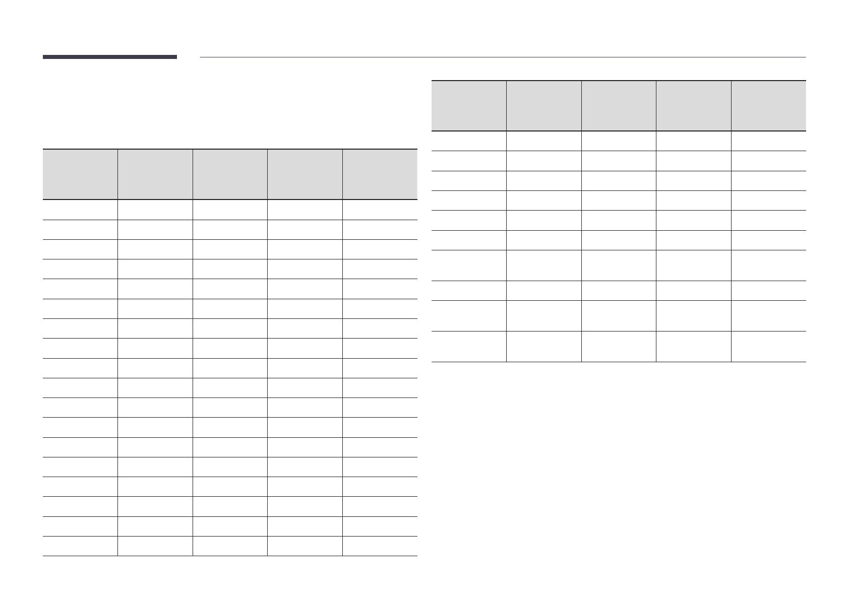
The screen will automatically be adjusted if a signal that belongs to the following standard
signal modes is transmitted from your PC. If the signal transmitted from the PC does not belong
to the standard signal modes, the screen may be blank with the power indicator on. In such a
case, change the settings according to the following table by referring to the graphics card user
manual.
Resolution
Horizontal
Frequency
(kHz)
Vertical
Frequency
(Hz)
Pixel Clock
(MHz)
Sync Polarity
(H/V)
IBM, 640 x 480 31.469 59.940 25.175 -/-
IBM, 720 x 400 31.469 70.087 28.322 -/+
MAC, 640 x 480 35.000 66.667 30.240 -/-
MAC, 832 x 624 49.726 74.551 57.284 -/-
MAC, 1152 x 870 68.681 75.062 100.000 -/-
VESA, 640 x 480 31.469 59.940 25.175 -/-
VESA, 640 x 480 37.861 72.809 31.500 -/-
VESA, 640 x 480 37.500 75.000 31.500 -/-
VESA, 800 x 600 35.156 56.250 36.000 +/+
VESA, 800 x 600 37.879 60.317 40.000 +/+
VESA, 800 x 600 48.077 72.188 50.000 +/+
VESA, 800 x 600 46.875 75.000 49.500 +/+
VESA, 1024 x 768 48.363 60.004 65.000 -/-
VESA, 1024 x 768 56.476 70.069 75.000 -/-
VESA, 1024 x 768 60.023 75.029 78.750 +/+
VESA, 1152 x 864 67.500 75.000 108.000 +/+
VESA, 1280 x 720 45.000 60.000 74.250 +/+
VESA, 1280 x 800 49.702 59.810 83.500 -/+
Resolution
Horizontal
Frequency
(kHz)
Vertical
Frequency
(Hz)
Pixel Clock
(MHz)
Sync Polarity
(H/V)
VESA, 1280 x 1024 63.981 60.020 108.000 +/+
VESA, 1280 x 1024 79.976 75.025 135.000 +/+
VESA, 1366 x 768 47.712 59.790 85.500 +/+
VESA, 1440 x 900 55.935 59.887 106.500 -/+
VESA, 1600 x 900 60.000 60.000 108.000 +/+
VESA, 1680 x 1050 65.290 59.954 146.250 -/+
VESA, 1920 x 1080
(DVI)
67.500 60.000 148.500 +/+
VESA, 2560 x 1440 88.787 59.951 241.500 +/-
CEA, 3840 x 2160
(HDMI)
67.500 60.000 297.000 +/+
VESA, 3840 x 2160
(DP)
133.313 59.997 533.250 +/-
"
The QBN and QE82N models are not available in the VESA 3840 x 2160 (DP).
  • Page 1 1
  • Page 2 2
  • Page 3 3
  • Page 4 4
  • Page 5 5
  • Page 6 6
  • Page 7 7
  • Page 8 8
  • Page 9 9
  • Page 10 10
  • Page 11 11
  • Page 12 12
  • Page 13 13
  • Page 14 14
  • Page 15 15
  • Page 16 16
  • Page 17 17
  • Page 18 18
  • Page 19 19
  • Page 20 20
  • Page 21 21

Samsung QM75N User manual

Type
User manual
This manual is also suitable for

Ask a question and I''ll find the answer in the document

Finding information in a document is now easier with AI