P/N 30-0312
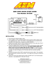
X-SERIES GAUGE
AEMnet CAN
AEM Performance Electronics, 2205 126th Street Unit A, Hawthorne, CA 90250 - Phone: (310) 484-2322
http://www.aemelectronics.com
STOP! - READ THIS BEFORE INSTALL OR USE!
WARNING:
THIS INSTALLATION MAY REQUIRE WELDING OR INTEGRATION INTO A VEHICLE'S ELECTRICAL SYSTEM. DAMAGE
TO SENSITIVE ELECTRONICS, FIRE, OR EXPLOSION MAY OCCUR IF PROPER PRECAUTION IS NOT TAKEN. IF THERE
IS ANY DOUBT, DO NOT ATTEMPT THE INSTALLATION AND CONSULT A PROFESSIONAL.
NOTE: IT IS THE RESPONSIBILITY OF THE ENGINE TUNER TO ULTIMATELY CONFIRM THE CALIBRATION USE FOR
ANY PARTICULAR ENGINE IS SAFE FOR ITS INTENDED USE. AEM HOLDS NO RESPONSIBILITY FOR ANY ENGINE
DAMAGE THAT RESULTS FROM THE MISUSE OF THIS PRODUCT.
Instruction
Manual
Features
2-1/16" / 52mm outer diameter mounting
62 AEMnet channels supported
Supported devices: Infinity ECU, Series 2 ECU, EMS-
4, 4 Channel UEGO, X-Series UEGO, VDM
Auto-hides channels from devices that aren't present
Ability to hide/show channels from devices that are
present
Peak recall for each channel
US or Metric / SI display modes
Black bezel / faceplate supplied; Silver/white available
as optional purchase
Locking connectors
Auto-dimming
Supports vehicle / system voltages up to 16V
KIT CONTENTS
PN
Description
10-0312
INST, X-SERIES AEMNET CAN GAUGE
35-0312
GAUGE ASSY, X-SERIES AEMNET CAN GAUGE
35-8618
NUT, KNURLED, M4x0.7 (2)
35-8614
BRACKET, X-SERIES GAUGE
35-8617
RUBBER BAND, X-SERIES GAUGE
35-3437
CABLE, X-SERIES GAUGE PWR/IO CAN
*OPTIONAL* ACCESSORIES
PN
Description
30-0312-
ACC
BEZEL, X-SERIES SILVER
FACEPLATE, X-SERIES AEMNET, WHITE

2
2017-11-07 - DOCUMENT NUMBER: 10-0312
© 2017 AEM Performance Electronics
30-0312 - AEMnet CAN
Wiring Installation Diagram
Connector A - Power / IO
Pin
Color
Description
1
RED
Switched 12V Power
2
BLACK
Power Ground
3
GREEN
AEMnet-/ CANL
4
WHITE
AEMnet+/ CANH
5 - 10
NC
NC

3
2017-11-07 - DOCUMENT NUMBER: 10-0312
© 2017 AEM Performance Electronics
30-0312 - AEMnet CAN
Operation
The PAGE button may be depressed to scroll through the available AEMnet channels;
an abbreviation of each channel name will be briefly displayed after each button press.
The inner numeric LEDs and outer ring LED display the currently selected channel
reading. Channels will only be present in the channel list if the corresponding AEMnet
device is presently connected to the bus, powered, and transmitting. Please
reference the AEMnet Channel description table further on in this document.
PAGE and PEAK buttons are located on the face of the gauge and are used to
perform various functions, described below.
Display or clear stored peak value
Press the PEAK button; the peak (highest) reading of the currently selected
channel will be displayed and the outer LED will flash.
The peak value will be retained across power cycles.
While the peak value is being displayed, depress and hold the PEAK button for
three seconds until "CLr" appears to clear the peak values.
This operation will clear the peak values of ALL channels.
Will be displayed to confirm the peak value has been reset
The gauge will return to normal display mode a few seconds after the last button
press
Change channel display units US / SI (metric)
The gauge should be in its normal display mode,
showing the current parameter reading.
Depress and hold the PAGE button for three
seconds until US or SI appears.
Press the PAGE button to toggle between US or SI
(metric) modes.
This setting will apply to all channels EXCEPT
wideband O2 channels.
The gauge will return to normal display mode a few
seconds after the last button press.
Change wideband O2 display units AFR / Lambda
The gauge should be in its normal display mode, showing a
wideband/oxygen sensor channel reading.
Depress and hold the PAGE button for three seconds until
US or SI appears.
Press the PAGE button to toggle between AFR or Lambda
modes.
This setting will apply to all wideband O2 channels.
The gauge will return to normal display mode a few seconds
after the last button press.
Hide or show channels
If multiple AEMnet devices are present on the bus, the channel list can grow to be quite long, up to 62 channels. This can
make it time consuming to scroll through and find a specific channel to display. A hide/show feature is available to
remove infrequently viewed channels from the channel list.
Depress both the PAGE and PEAK buttons to display "HidE" and begin selecting
which channels to hide/show in the channel list.
Use the PAGE button to scroll through the channel list and the depress the PEAK
button to toggle between hide and show.
The gauge will return to normal display mode a few seconds after the last button
press.
All outer LEDs illuminated = SHOW
All outer LEDs off = HIDE

4
2017-11-07 - DOCUMENT NUMBER: 10-0312
© 2017 AEM Performance Electronics
30-0312 - AEMnet CAN
Faceplate / Bezel Installation
The gauge kit is supplied assembled with a black faceplate and black bezel. An accessory kit is available (for purchase
through AEM dealers) which includes an optional silver bezel and white faceplate. Please reference the Optional
Accessories section earlier in the document for the appropriate part numbers. Contact your dealer or visit
www.aemelectronics.com for more information.
The faceplate may be reversible, displaying alternative scalings on either side. Reference the Operation section of this
manual for details on how to switch the display mode when reversing the faceplate. Disassembly is required to change
the faceplate, flip/reverse the faceplate, or change the bezel of the gauge. The following diagram will provide familiarization
with the major components of the gauge prior to beginning the procedure.
Item
Qty
Description
1
1
Lens
2
1
Bezel
3
1
Faceplate
4
1
Diffuser
5
1
Light Guide
6
2
Button
7
2
Mounting Stud (M4 x 0.7)
8
3
Assembly Screw
9
1
Mounting Bracket
10
2
Brass Thumb Screw (M4 x 0.7)
11
1
Printed Circuit Board (PCB)

5
2017-11-07 - DOCUMENT NUMBER: 10-0312
© 2017 AEM Performance Electronics
30-0312 - AEMnet CAN
Gauge Disassembly
STEP 1 - Remove the three assembly screws (8) using a #1 Phillips
head screwdriver. Separate the bezel (2) and cup (7) from the rest of the
assembly. If you have purchased the optional accessory kit, the silver
bezel may be replaced for the existing bezel at this time
STEP 2 - Separate the PCB (11) from the remaining components
STEP 3 - Slide the light guide (5) upward to remove it, the buttons may
fall out at this time - take care not to lose them
STEP 4 - As you separate the remaining components, diffuser (4),
faceplate (3), lens (1), note the order in which they were assembled.
The faceplate (3) may now be reversed to display an alternate scaling or
replaced for a different color as included in the optional accessory kit

6
2017-11-07 - DOCUMENT NUMBER: 10-0312
© 2017 AEM Performance Electronics
30-0312 - AEMnet CAN
Gauge Assembly
STEP 1 - Place the light guide (5) on a flat surface (black side up) and
slide the buttons (6) into the slots
STEP 2 - Stack the diffuser (4), faceplate (3), and lens (1) in order, over
the buttons, and on to the light guide
STEP 3 - Reassemble the PCB and display stack with the bezel, making
sure screw holes are aligned through the entire assembly
STEP 4 - Reassemble and tighten screws to 2 in-lb (previously
assembled bezel) or 3 in-lb (new bezel). Do not over-tighten!

7
2017-11-07 - DOCUMENT NUMBER: 10-0312
© 2017 AEM Performance Electronics
30-0312 - AEMnet CAN
Gauge Installation
Installation using supplied bracket
Installation without bracket, using rubber band
A 2-1/6" (52mm) hole is required to mount the X-Series gauge. A bracket and thumbscrews are provided to facilitate
installation into a panel or gauge pod. In some cases, the gauge cup may be pushed into a mounting hole causing an
interference fit strong enough to retain the gauge; the supplied rubber band may be fit to the gauge to create a tighter fit in
mounting holes slightly larger than 52mm. It is, however, recommended that gauges be mounted securely using the
supplied bracket to ensure they never become loose and cause a hazard during vehicle operation.
Note: The gauge is not water-proof and should not be installed in a location with exposure to water or snow. Damage
caused by water ingress will not be covered under warranty.
AEMnet Channels
Display Label
Description
US
SI
Source
AF.Fb
Inj 1 LambdaFB
%
%
Infinity EMS
AFr.1
Lambda 1
AFR
EMS Series 2 / EMS-4 / Infinity
AFr.2
Lambda 2
AFR
EMS Series 2 / EMS-4 / Infinity
ALt
Altitude
ft
m
VDM
bAtt
Battery Volts
V
V
EMS Series 2 / EMS-4 / Infinity
bSt.d
Boost Control Duty
%
%
Infinity EMS
bSt.t
Boost Target
psig
kPa
Infinity EMS
CUt.S
SparkCut [RPM]
rpm
rpm
Infinity EMS
CYL.1
Lambda 1
AFR
4 Channel UEGO set on MODE 1
CYL.1
Lambda 1
AFR
4 Channel UEGO set on MODE 3
CYL.1
Lambda 1
AFR
4 Channel UEGO set on MODE 6
CYL.2
Lambda 2
AFR
4 Channel UEGO set on MODE 1
CYL.2
Lambda 2
AFR
4 Channel UEGO set on MODE 4
CYL.2
Lambda 2
AFR
4 Channel UEGO set on MODE 6
CYL.3
Lambda 3
AFR
4 Channel UEGO set on MODE 1
CYL.3
Lambda 3
AFR
4 Channel UEGO set on MODE 3
CYL.3
Lambda 3
AFR
4 Channel UEGO set on MODE 6
CYL.4
Lambda 4
AFR
4 Channel UEGO set on MODE 1
CYL.4
Lambda 4
AFR
4 Channel UEGO set on MODE 4
CYL.4
Lambda 4
AFR
4 Channel UEGO set on MODE 7
CYL.5
Lambda 5
AFR
4 Channel UEGO set on MODE 2
CYL.5
Lambda 5
AFR
4 Channel UEGO set on MODE 3
CYL.5
Lambda 5
AFR
4 Channel UEGO set on MODE 7
CYL.6
Lambda 6
AFR
4 Channel UEGO set on MODE 2
CYL.6
Lambda 6
AFR
4 Channel UEGO set on MODE 4

8
2017-11-07 - DOCUMENT NUMBER: 10-0312
© 2017 AEM Performance Electronics
30-0312 - AEMnet CAN
CYL.6
Lambda 6
AFR
4 Channel UEGO set on MODE 7
CYL.7
Lambda 7
AFR
4 Channel UEGO set on MODE 2
CYL.7
Lambda 7
AFR
4 Channel UEGO set on MODE 3
CYL.8
Lambda 8
AFR
4 Channel UEGO set on MODE 2
CYL.8
Lambda 8
AFR
4 Channel UEGO set on MODE 4
E.SPd
Engine Speed
rpm
rpm
EMS Series 2 / EMS-4 / Infinity
EtH
FlexContent
%
%
Infinity EMS
G.Lat
Lateral Acceleration
g
g
VDM
G.Lon
Inline Acceleration
g
g
VDM
G.SPd
Vehicle Speed
mph
kph
VDM
GEAr
Gear Calculated
n/a
n/a
EMS Series 2 / EMS-4 / Infinity
Ign.r
Knock FB (max)
deg
deg
Infinity EMS
Ign.t
Ignition Timing
deg
deg
EMS Series 2 / EMS-4 / Infinity
InJ.d
Primary Inj Duty %
%
%
Infinity EMS
LoAd
Load
%
%
EMS Series 2 / EMS-4
o2-1
Lambda 1
AFR
X-Series UEGO devices
o2-2
Lambda 2
AFR
X-Series UEGO devices
o2-3
Lambda 3
AFR
X-Series UEGO devices
o2-4
Lambda 4
AFR
X-Series UEGO devices
o2-5
Lambda 5
AFR
X-Series UEGO devices
o2-6
Lambda 6
AFR
X-Series UEGO devices
o2-7
Lambda 7
AFR
X-Series UEGO devices
o2-8
Lambda 8
AFR
X-Series UEGO devices
Pbro
Baro Press
inHg
kPa
Infinity EMS
PbSt
MAP
psig
kPa
Infinity EMS
PCLt
Cool ant Pre ssure
psig
bar
Infinity EMS
PFUE
Fuel Pressure
psig
bar
Infinity EMS
POIL
Oil Pressure
psig
bar
Infinity EMS
PPAn
Crankcase Pre ssure
psig
kPa
Infinity EMS
SLIP
TC_SlipMeasured
mph
kph
Infinity EMS
SPd
Vehicle Speed
mph
kph
EMS Series 2 / EMS-4 / Infinity
tAb
Airbox Temp
degF
degC
Infinity EMS
tCLt
Coolant Temp
degF
degC
EMS Series 2 / EMS-4 / Infinity
tIAt
Intake Air Temp
degF
degC
EMS Series 2 / EMS-4 / Infinity
tOIL
Oil Temp
degF
degC
Infinity EMS
ttrn
Trans Temp
degF
degC
Infinity EMS
tPS
Throttle
%
%
EMS Series 2 / EMS-4 / Infinity
FAQ / Troubleshooting
I installed my gauge correctly and the display just shows "CAn"
The gauge is not detecting the expected AEMnet/CAN traffic. Please check that you have other AEMnet enabled devices
connected to the bus, properly terminated, and powered on. For custom installations, refer to the Bosch CAN 2.0b
specification for proper wiring and termination techniques.
What pins are used in the connector?
To populate optional extras, use JST P/N SPUD-001T-P0.5 terminals for 22-26 AWG wire.
For support, contact AEM Technical Support at 1-800-423-0046 or gentech@aemelectronics.com.

9
2017-11-07 - DOCUMENT NUMBER: 10-0312
© 2017 AEM Performance Electronics
30-0312 - AEMnet CAN
Specifications
Dimensions
diameter (bezel)
2.40
in
diameter (cup)
2-1/16
in
depth (incl. bezel)
0.825
in
depth (cup only)
0.200
in
Supply Voltage
min
10
VDC
max
18
VDC
Supply Current (13.8V)
nominal
50.0
mA
Operating Temperature
min
-4 / -20
degF / degC
max (16V Supply)
185 / 85
degF / degC
12 Month Limited Warranty
Advanced Engine Management Inc. warrants to the consumer that all AEM High Performance products will be free from defects in material and
workmanship for a period of twelve (12) months from date of the original purchase. Products that fail w ithin this 12-month warranty period will be
repaired or replaced at AEM’s option, when determined by AEM that the product failed due to defects in material or workmanship. This w arranty is
limited to the repair or replacement of the AEM part. In no event shall this warranty exceed the original purchase price of the AEM part nor shall
AEM be responsible for special, incidental or consequential damages or cost incurred due to the failure of this product. Warranty claims to AEM
must be transportation prepaid and accompanied w ith dated proof of purchase. This warranty applies only to the original purchaser of product
and is non-transferable. All implied w arranties shall be limited in duration to the said 12-month warranty period. Improper use or installation,
accident, abuse, unauthorized repairs or alterations voids this w arranty. AEM disclaims any liability for consequential damages due to breach of
any written or implied warranty on all products manufactured by AEM. Warranty returns will only be accepted by AEM when accompanied by a
valid Return Merchandise Authorization (RMA) number. Product must be received by AEM within 30 days of the date the RMA is issued.
UEGO oxygen sensors are considered wear items and are not covered under warranty.
Please note that before AEM can issue an RMA for any electronic product, it is first necessary for the installer or end user to contact the EMS
tech line at 1-800-423-0046 to discuss the problem. Most issues can be resolved over the phone. Under no circumstances should a system be
returned or a RMA requested before the above process transpires.
AEM will not be responsible for electronic products that are installed incorrectly, installed in a non-approved application, misused, or tampered
with.
Any AEM electronics product can be returned for repair if it is out of the warranty period. There is a minimum charge of $50.00 for inspection and
diagnosis of AEM electronic parts. Parts used in the repair of AEM electronic components will be extra. AEM will provide an estimate of repairs
and receive written or electronic authorization before repairs are made to the product.
/