Escala PL460R Installation guide

Category
Servers
Type
Installation guide

This manual is also suitable for

PL160T/R,
PL260T/T and
PL460T/R
Installation Guide
ESCALA
REFERENCE
86 A1 55EW 01
ESCALA
PL160T/R, PL260T/T and
PL460T/R
Installation Guide
Hardware
July 2008
BULL CEDOC
357 AVENUE PATTON
B.P.20845
49008 ANGERS CEDEX 01
FRANCE
REFERENCE
86 A1 55EW 01
The following copyright notice protects this book under Copyright laws which prohibit such actions as, but not limited
to, copying, distributing, modifying, and making derivative works.
Copyright IBM, 2007-2008
Copyright © Bull SAS 2007-2008
Printed in France
Trademarks and Acknowledgements
We acknowledge the rights of the proprietors of the trademarks mentioned in this manual.
All brand names and software and hardware product names are subject to trademark and/or patent protection.
Quoting of brand and product names is for information purposes only and does not represent trademark misuse.
The information in this document is subject to change without notice. Bull will not be liable for errors
contained herein, or for incidental or consequential damages in connection with the use of this material.
Contents
Safety notices . . . . . . . . . . . . . . . . . . . . . . . . . . . . . . . . .v
About this publication . . . . . . . . . . . . . . . . . . . . . . . . . . . . . vii
How to send your comments . . . . . . . . . . . . . . . . . . . . . . . . . . . . . vii
Installing the model 03E/4A . . . . . . . . . . . . . . . . . . . . . . . . . .1
Chapter 1. Prerequisite tasks for the 03E/4A installation . . . . . . . . . . . . . . .3
Chapter 2. Installing your system in a rack . . . . . . . . . . . . . . . . . . . . .5
Installing the rack . . . . . . . . . . . . . . . . . . . . . . . . . . . . . . . . .5
Rack safety notices . . . . . . . . . . . . . . . . . . . . . . . . . . . . . . . .5
Determining the location . . . . . . . . . . . . . . . . . . . . . . . . . . . . . .7
Marking location by using the rack-mounting template . . . . . . . . . . . . . . . . . . .8
Marking the location without a rack-mounting template . . . . . . . . . . . . . . . . . .10
Installing the 14T/00, 14T/42 racks . . . . . . . . . . . . . . . . . . . . . . . . . .11
Completing a parts inventory . . . . . . . . . . . . . . . . . . . . . . . . . . .11
Positioning the rack . . . . . . . . . . . . . . . . . . . . . . . . . . . . . .11
Leveling the rack . . . . . . . . . . . . . . . . . . . . . . . . . . . . . . .12
Attaching the stabilizer brackets . . . . . . . . . . . . . . . . . . . . . . . . . .13
Attaching the rack to a concrete floor . . . . . . . . . . . . . . . . . . . . . . . . .14
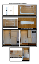
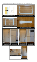
Attaching the rack doors . . . . . . . . . . . . . . . . . . . . . . . . . . . .19
Connecting multiple racks with rack-to-rack attachment kit . . . . . . . . . . . . . . . .21
Attaching the rack to the concrete floor beneath a raised floor . . . . . . . . . . . . . . . .23
Connecting the power distribution system . . . . . . . . . . . . . . . . . . . . . . .27
Power distribution unit plus (PDU+) . . . . . . . . . . . . . . . . . . . . . . . . .27
Checking the ac outlets . . . . . . . . . . . . . . . . . . . . . . . . . . . . .27
Attaching the front or back ac electrical outlet . . . . . . . . . . . . . . . . . . . . . .28
Installing the ac outlet-mounting plates with ac outlets . . . . . . . . . . . . . . . . . .28
Installing the ac outlet-mounting plate without ac outlets . . . . . . . . . . . . . . . . .30
Connecting a dc power source . . . . . . . . . . . . . . . . . . . . . . . . . . .31
Installing the rack security kit . . . . . . . . . . . . . . . . . . . . . . . . . . .35
Installing the model in a rack . . . . . . . . . . . . . . . . . . . . . . . . . . . . .38
Attaching the mounting hardware to the rack . . . . . . . . . . . . . . . . . . . . . . .40
Installing the cable-management arm . . . . . . . . . . . . . . . . . . . . . . . . . .43
Chapter 3. Installing an 03E/4A with logical partitions . . . . . . . . . . . . . . .45
Checklist: Installing an 03E/4A with logical partitions . . . . . . . . . . . . . . . . . . . . .45
Cabling your server . . . . . . . . . . . . . . . . . . . . . . . . . . . . . . . .45
Cabling the server and the Hardware Management Console (HMC) . . . . . . . . . . . . . . .46
Cabling the server to access the Integrated Virtualization Manager . . . . . . . . . . . . . . . .49
Cabling the server to access the Operations Console . . . . . . . . . . . . . . . . . . . . .53
Setting up your console or interface and create logical partitions . . . . . . . . . . . . . . . . .58
Setting up the HMC and create logical partitions . . . . . . . . . . . . . . . . . . . . . .58
Setting up Virtual I/O Server, IVM, and logical partitions . . . . . . . . . . . . . . . . . . .59
Setting up the Operations Console, twinaxial console, or 5250 console and creating logical partitions . . . .59
Setting up your server to connect to service and support . . . . . . . . . . . . . . . . . . . .60
Installing operating systems . . . . . . . . . . . . . . . . . . . . . . . . . . . . . .60
Obtaining updates and upgrades . . . . . . . . . . . . . . . . . . . . . . . . . . . .60
Chapter 4. Installing a model 03E/4A without logical partitions . . . . . . . . . . . .61
Checklist: Installing an 03E/4A without logical partitions . . . . . . . . . . . . . . . . . . . .61
Cabling your server . . . . . . . . . . . . . . . . . . . . . . . . . . . . . . . .61
Cabling the server and the Hardware Management Console (HMC) . . . . . . . . . . . . . . .62
iii
Cabling the server to access the Advanced System Management Interface (ASMI) . . . . . . . . . . .65
Cabling the server to access the Operations Console . . . . . . . . . . . . . . . . . . . . .69
Setting up your console, terminal, or interface to manage your system . . . . . . . . . . . . . . .74
Setting up the HMC . . . . . . . . . . . . . . . . . . . . . . . . . . . . . . .74
Connecting to ASMI or SMS menus . . . . . . . . . . . . . . . . . . . . . . . . . .75
Setting up the Operations Console or 5250 console . . . . . . . . . . . . . . . . . . . . .75
Setting up your server to connect to service and support . . . . . . . . . . . . . . . . . . . .75
Installing operating systems . . . . . . . . . . . . . . . . . . . . . . . . . . . . . .75
Obtaining updates and upgrades . . . . . . . . . . . . . . . . . . . . . . . . . . . .76
Chapter 5. Common procedures (installing operating systems and obtaining updates)
for the model 03E/4A . . . . . . . . . . . . . . . . . . . . . . . . . . . . .77
Installing AIX . . . . . . . . . . . . . . . . . . . . . . . . . . . . . . . . . .77
Installing . . . . . . . . . . . . . . . . . . . . . . . . . . . . . . . . . . . .77
Installing Linux . . . . . . . . . . . . . . . . . . . . . . . . . . . . . . . . . .77
Configuring Electronic Service Agent on standalone AIX systems . . . . . . . . . . . . . . . . .77
Obtaining HMC machine code updates and upgrades . . . . . . . . . . . . . . . . . . . . .79
Obtaining firmware updates . . . . . . . . . . . . . . . . . . . . . . . . . . . . . .79
Updating the Virtual I/O Server’s firmware and device microcode through the Integrated Virtualization
Manager with an Internet connection . . . . . . . . . . . . . . . . . . . . . . . . . .79
Step 1. View the existing firmware level . . . . . . . . . . . . . . . . . . . . . . . .79
Step 2. Apply firmware and device microcode using the IVM . . . . . . . . . . . . . . . . .79
Step 3. Verify that the firmware updated correctly . . . . . . . . . . . . . . . . . . . .80
Updating the Virtual I/O Server’s firmware and device microcode through the Integrated Virtualization
Manager without an Internet connection . . . . . . . . . . . . . . . . . . . . . . . . .80
Step 1. Obtain the hardware microcode and firmware CD . . . . . . . . . . . . . . . . . .80
Step 1. Obtain the firmware update on CD . . . . . . . . . . . . . . . . . . . . . . .81
Step 2. Apply firmware and device microcode using the IVM . . . . . . . . . . . . . . . . .81
Step 3. Verify that the firmware updated correctly . . . . . . . . . . . . . . . . . . . .82
Obtaining operating system fixes . . . . . . . . . . . . . . . . . . . . . . . . . . . .82
Obtaining operating system fixes for AIX or Linux . . . . . . . . . . . . . . . . . . . . .82
Place the rack-mounted model 04E/8A, 03E/4A in the service position . . . . . . . . . . . . . . .82
Appendix. Accessibility features . . . . . . . . . . . . . . . . . . . . . . . . .87
Notices . . . . . . . . . . . . . . . . . . . . . . . . . . . . . . . . . . .89
Trademarks . . . . . . . . . . . . . . . . . . . . . . . . . . . . . . . . . . .90
Electronic emission notices . . . . . . . . . . . . . . . . . . . . . . . . . . . . . .90
Class A Notices . . . . . . . . . . . . . . . . . . . . . . . . . . . . . . . . .90
Terms and conditions . . . . . . . . . . . . . . . . . . . . . . . . . . . . . . . .94
iv Installation Guide for the 03E/4A, 07M/15, and 08M/25
Safety notices
Safety notices may be printed throughout this guide.
v DANGER notices call attention to a situation that is potentially lethal or extremely hazardous to
people.
v CAUTION notices call attention to a situation that is potentially hazardous to people because of some
existing condition.
v Attention notices call attention to the possibility of damage to a program, device, system, or data.
World Trade safety information
Several countries require the safety information contained in product publications to be presented in their
national languages. If this requirement applies to your country, a safety information booklet is included
in the publications package shipped with the product. The booklet contains the safety information in
your national language with references to the U.S. English source. Before using a U.S. English publication
to install, operate, or service this product, you must first become familiar with the related safety
information in the booklet. You should also refer to the booklet any time you do not clearly understand
any safety information in the U.S. English publications.
Laser safety information
The servers can use I/O cards or features that are fiber-optic based and that utilize lasers or LEDs.
Laser compliance
All lasers are certified in the U.S. to conform to the requirements of DHHS 21 CFR Subchapter J for class
1 laser products. Outside the U.S., they are certified to be in compliance with IEC 60825 as a class 1 laser
product. Consult the label on each part for laser certification numbers and approval information.
CAUTION:
This product might contain one or more of the following devices: CD-ROM drive, DVD-ROM drive,
DVD-RAM drive, or laser module, which are Class 1 laser products. Note the following information:
v Do not remove the covers. Removing the covers of the laser product could result in exposure to
hazardous laser radiation. There are no serviceable parts inside the device.
v Use of the controls or adjustments or performance of procedures other than those specified herein
might result in hazardous radiation exposure.
(C026)
CAUTION:
Data processing environments can contain equipment transmitting on system links with laser modules
that operate at greater than Class 1 power levels. For this reason, never look into the end of an optical
fiber cable or open receptacle. (C027)
CAUTION:
This product contains a Class 1M laser. Do not view directly with optical instruments. (C028)
CAUTION:
Some laser products contain an embedded Class 3A or Class 3B laser diode. Note the following
information: laser radiation when open. Do not stare into the beam, do not view directly with optical
instruments, and avoid direct exposure to the beam. (C030)
v
Power and cabling information for NEBS (Network Equipment-Building System)
GR-1089-CORE
The following comments apply to the servers that have been designated as conforming to NEBS
(Network Equipment-Building System) GR-1089-CORE:
The equipment is suitable for installation in the following:
v Network telecommunications facilities
v Locations where the NEC (National Electrical Code) applies
The
intrabuilding ports of this equipment are suitable for connection to intrabuilding or unexposed
wiring or cabling only. The intrabuilding ports of this equipment must not be metallically connected to the
interfaces that connect to the OSP (outside plant) or its wiring. These interfaces are designed for use as
intrabuilding interfaces only (Type 2 or Type 4 ports as described in GR-1089-CORE) and require isolation
from the exposed OSP cabling. The addition of primary protectors is not sufficient protection to connect
these interfaces metallically to OSP wiring.
Note: All Ethernet cables must be shielded and grounded at both ends.
The ac-powered system does not require the use of an external surge protection device (SPD).
The dc-powered system employs an isolated DC return (DC-I) design. The DC battery return terminal
shall not be connected to the chassis or frame ground.
vi Installation Guide for the 03E/4A, 07M/15, and 08M/25
About this publication
This book contains instructions to assist you in setting up your server. It is intended to ensure that the
system is running and is functional before you perform more complex and custom configurations.
For information about the accessibility features of this product, for users who have a physical disability,
see “Accessibility features,” on page 87.
How to send your comments
Your feedback is important in helping to provide the most accurate and highest quality information. If
you have any comments about this publication, send your comments to us. Be sure to include the name
of the book and the specific location of the text you are commenting on (for example, a page number or
table number).
vii
viii Installation Guide for the 03E/4A, 07M/15, and 08M/25
Installing the model 03E/4A
This book contains the tasks and information that is needed to set up your system in order to get it
running and into production.
Chapters 3 and 4 in this book have been broken down into two sections: installing an 03E/4A with
logical partitions and installing an 03E/4A without logical partitions. Each of those sections has a
separate checklist that you can use as a guide to assist you in setting up your system. The tasks listed
within each section and checklist are listed in chronological order. This will help give you an idea of what
tasks need to be completed when. Not all tasks that are listed need to be completed. That will depend on
your particular situation. For example, you might not be installing your system in a rack in which case
those tasks do not have to be completed.
See one of the following sections to continue:
v Chapter 3, “Installing an 03E/4A with logical partitions,” on page 45
v Chapter 4, “Installing a model 03E/4A without logical partitions,” on page 61
1
2 Installation Guide for the 03E/4A, 07M/15, and 08M/25
Chapter 1. Prerequisite tasks for the 03E/4A installation
Prior to setting up and installing your new system, complete the following tasks to ensure that you are
prepared for the installation.
1. If you are using a previously existing Hardware Management Console (HMC), you need to ensure
that your HMC is at the correct code level (7.3.2 or later).
To update your HMC code level, see Chapter 8, ”Updating, upgrading, and migrating your HMC
machine code in the Installation and Configuration Guide for the Hardware Management Console.
To view the PDF file of the Installation and Configuration Guide for the Hardware Management Console
(SA76-0084), approximately 3 MB in size, see sa76-0084.pdf
.
2. The System Planning Tool (SPT) helps you design a managed system that can support a specified set
of workloads. When you are done making changes to the system, you can save your work as a
system plan. You can import this file into your Hardware Management Console (HMC) or the
management partition for the Integrated Virtualization Manager (for systems that have multiple
logical partitions) and deploy the system plan to a managed system. When you deploy the system
plan, the HMC or the Integrated Virtualization Manager creates the logical partitions from the system
plan on the managed system
3
4 Installation Guide for the 03E/4A, 07M/15, and 08M/25
Chapter 2. Installing your system in a rack
Complete these tasks to install your system in a rack.
To install your system in a rack, perform the tasks in “Installing the model in a rack” on page 38.
Installing the rack
You might need to install the rack. Use the procedure in this section to perform this task.
Rack safety notices
You will need to read the rack safety notices before installing equipment. Use the procedure in this
section to perform this task.
Before installing a rack, rack features, or a system or expansion unit into a rack, read the following safety
information:
Attention: If you are installing equipment into a rack, the rack must comply with the Electronics
Industries Association (EIA) 310D specifications. If you do not have a rail kit designed for the equipment
in the rack, do not install the equipment into the rack as damage to the equipment or personal injury
could occur.
5
DANGER
Observe
the following precautions when working on or around your IT rack system:
v Heavy equipment–personal injury or equipment damage might result if mishandled.
v Always lower the leveling pads on the rack cabinet.
v Always install stabilizer brackets on the rack cabinet.
v To avoid hazardous conditions due to uneven mechanical loading, always install the heaviest
devices in the bottom of the rack cabinet. Always install servers and optional devices starting
from the bottom of the rack cabinet.
v Rack-mounted devices are not to be used as shelves or work spaces. Do not place objects on top
of rack-mounted devices.
v Each rack cabinet might have more than one power cord. Be sure to disconnect all power cords in
the rack cabinet when directed to disconnect power during servicing.
v Connect all devices installed in a rack cabinet to power devices installed in the same rack
cabinet. Do not plug a power cord from a device installed in one rack cabinet into a power
device installed in a different rack cabinet.
v An electrical outlet that is not correctly wired could place hazardous voltage on the metal parts of
the system or the devices that attach to the system. It is the responsibility of the customer to
ensure that the outlet is correctly wired and grounded to prevent an electrical shock.
CAUTION
v Do not install a unit in a rack where the internal rack ambient temperatures will exceed the
manufacturer’s recommended ambient temperature for all your rack-mounted devices.
v Do not install a unit in a rack where the air flow is compromised. Ensure that air flow is not
blocked or reduced on any side, front, or back of a unit used for air flow through the unit.
v Consideration should be given to the connection of the equipment to the supply circuit so that
overloading of the circuits does not compromise the supply wiring or overcurrent protection. To
provide the correct power connection to a rack, refer to the rating labels located on the
equipment in the rack to determine the total power requirement of the supply circuit.
v (For sliding drawers.) Do not pull out or install any drawer or feature if the rack stabilizer brackets
are not attached to the rack. Do not pull out more than one drawer at a time. The rack might
become unstable if you pull out more than one drawer at a time.
v (For fixed drawers.) This drawer is a fixed drawer and must not be moved for servicing unless
specified by the manufacturer. Attempting to move the drawer partially or completely out of the
rack might cause the rack to become unstable or cause the drawer to fall out of the rack.
(R001)
Lift precautions:
6 Installation Guide for the 03E/4A, 07M/15, and 08M/25
Determining the location
You might need to determine where to install the system in the rack. This section includes procedures so
that you can perform these tasks.
Before installing the system unit into a rack, complete the following steps:
1. Read the “Rack safety notices” on page 5.
2. Plan where you will place the units. Place the larger and heavier units in the lower part of the rack.
This system unit is four Electronic Industries Alliance (EIA) units high. An EIA unit is 1.75 in (44.45
mm) in height. The rack contains three mounting holes for each EIA unit of height. This system unit
therefore is 7 in high and covers 12 mounting holes in the rack.
3. If necessary, remove the filler panels to allow access to the inside of the rack enclosure where you
plan to place the unit.
Chapter 2. Installing your system in a rack 7
4. If necessary, remove the front and back rack doors.
5. Use the rack-mounting template to mark the location (see Mark location using the rack-mounting
template). If you do not have a rack-mounting template, following instructions for marking the
location without a template (see Mark the location without rack-mounting template).
Marking location by using the rack-mounting template
You might need to mark the installation location by using a rack-mounting template. Use the procedure
in this section to perform this task.
1. Using the rack-mounting template, determine where in the rack to place the unit. Install units in the
lower part of the rack first. Place larger and heavier units in the lower part of the rack.
Figure 1. Removing the filler panels.
8 Installation Guide for the 03E/4A, 07M/15, and 08M/25
Note: The front of the rack-mounting template has printed illustrations designed to help you identify
the mounting holes to be used when you add units to the rack. Do not use the rack-mounting
template without completing the following steps.
2. Note the following when using the rack-mounting template:
v Each black or white unit on the template is equal to one Electronic Industries Alliance (EIA) unit.
v An EIA unit is 1.75 in (44.45 mm) in height.
v The rack contains three mounting holes for each EIA unit of height.
v The EIA units that are illustrated on the template must be aligned with the EIA units located on the
rack.
v It is not necessary to align like-colored EIA units. For example, a black EIA unit on the
rack-mounting template can be aligned with a white EIA unit that are located on the rack.
v The template is two-sided. When using the template, ensure that the appropriate side of the
template is facing out.
Figure 3 shows one EIA unit and four EIA units. Depending on the rack manufacturer, the EIA units
might be separated either by color or by a line. Notice that the holes along the rail are not evenly
spaced. If your rack has no color or line separation between EIA units, assume that each EIA unit
begins where the hole spacing is closest together as shown by A in Figure 3.
To use the rack-mounting template, complete the following steps:
a. Remove the protective coating from each adhesive strip located on the back of the rack-mounting
template. Lightly press the template into position on the rack. Ensure that both the left and right
sides are at the corresponding EIA locations.
Figure 2. Rack-mounting template
Figure 3. EIA units
Chapter 2. Installing your system in a rack 9
Note: The tabs on each side of the template show a notch to indicate the correct spacing between
the front flanges.
b. Locate the dots that are printed on the left and right side of the template. Place a self-adhesive dot
directly across from the template’s printed dots on or near the rack’s EIA numbering strip. You
will be using these dots to aid in correctly positioning the rail-alignment pins located on the front
of each rail.
c. Remove the rack-mounting template from the front of the rack. The front of your rack should now
contain dots.
d. Mount the rack-mounting template to the rack’s back EIA frame. Place the rack-mounting template
at the same EIA-numbered location that was used on the front of the rack.
e. Wrap a self-adhesive dot directly across from the template’s printed dots. Ensure that a portion of
the self-adhesive dot wraps around the rack frame so that it can be seen from the front of the rack.
f. Remove the rack-mounting template from the back of the rack. The back of your rack should now
contain dots that have been partially wrapped around the frame.
Marking the location without a rack-mounting template
You might need to mark the location without using a template. Use the procedure in this section to
perform this task.
To mark the installation location and install the nut clips into a rack without using the rack-mounting
template, complete the following steps:
1. Determine where in the rack to place the system. Install units in the lower part of the rack first. Place
larger and heavier units in the lower part of the rack. Record the EIA location. The system is four
Electronic Industries Alliance (EIA) units high. An EIA unit is 1.75 in (44.45 mm) in height. The rack
contains three mounting holes for each EIA unit of height. This system therefore is 7 in high and
covers 12 mounting holes in the rack.
2. Facing the front of the rack and working from the right side, place a self-adhesive dot next to the
bottom hole of the bottom EIA unit of the four you will be using for this system unit A in Figure 4 on
page 11.
Note: The self-adhesive dots are used to aid in identifying locations on the rack. If you do not have
the dots, use some other form of marking tool to aid you in identifying hole locations (for example,
tape, or a marker). You will need to identify the marked hole from both the front and back of the
rack.
3. Place another self-adhesive dot next to the bottom hole of the bottom EIA unit on the left side of the
rack.
4. Go to the back of the rack. On the right side, find the EIA unit that corresponds to the bottom EIA
unit marked on the front of the rack.
10 Installation Guide for the 03E/4A, 07M/15, and 08M/25
  • Page 1 1
  • Page 2 2
  • Page 3 3
  • Page 4 4
  • Page 5 5
  • Page 6 6
  • Page 7 7
  • Page 8 8
  • Page 9 9
  • Page 10 10
  • Page 11 11
  • Page 12 12
  • Page 13 13
  • Page 14 14
  • Page 15 15
  • Page 16 16
  • Page 17 17
  • Page 18 18
  • Page 19 19
  • Page 20 20
  • Page 21 21
  • Page 22 22
  • Page 23 23
  • Page 24 24
  • Page 25 25
  • Page 26 26
  • Page 27 27
  • Page 28 28
  • Page 29 29
  • Page 30 30
  • Page 31 31
  • Page 32 32
  • Page 33 33
  • Page 34 34
  • Page 35 35
  • Page 36 36
  • Page 37 37
  • Page 38 38
  • Page 39 39
  • Page 40 40
  • Page 41 41
  • Page 42 42
  • Page 43 43
  • Page 44 44
  • Page 45 45
  • Page 46 46
  • Page 47 47
  • Page 48 48
  • Page 49 49
  • Page 50 50
  • Page 51 51
  • Page 52 52
  • Page 53 53
  • Page 54 54
  • Page 55 55
  • Page 56 56
  • Page 57 57
  • Page 58 58
  • Page 59 59
  • Page 60 60
  • Page 61 61
  • Page 62 62
  • Page 63 63
  • Page 64 64
  • Page 65 65
  • Page 66 66
  • Page 67 67
  • Page 68 68
  • Page 69 69
  • Page 70 70
  • Page 71 71
  • Page 72 72
  • Page 73 73
  • Page 74 74
  • Page 75 75
  • Page 76 76
  • Page 77 77
  • Page 78 78
  • Page 79 79
  • Page 80 80
  • Page 81 81
  • Page 82 82
  • Page 83 83
  • Page 84 84
  • Page 85 85
  • Page 86 86
  • Page 87 87
  • Page 88 88
  • Page 89 89
  • Page 90 90
  • Page 91 91
  • Page 92 92
  • Page 93 93
  • Page 94 94
  • Page 95 95
  • Page 96 96
  • Page 97 97
  • Page 98 98
  • Page 99 99
  • Page 100 100
  • Page 101 101
  • Page 102 102
  • Page 103 103
  • Page 104 104
  • Page 105 105
  • Page 106 106

Escala PL460R Installation guide

Category
Servers
Type
Installation guide
This manual is also suitable for

Ask a question and I''ll find the answer in the document

Finding information in a document is now easier with AI