31-10985-1
3
WARNING – The electrical power to
the cooktop supply line must be shut off while
connections are being made. Failure to do so
could result in serious injury or death.
A
When preparing cooktop opening, make sure the
inside of the cabinet and the cooktop do not
interfere with each other. (See section on
preparing the opening.)
B
Remove packaging materials and literature
package from the cooktop before beginning
installation.
C
Be sure to place all literature, Owner’s Manual,
Installations, etc. in a safe place for future
reference.
D
Make sure you have all the tools and materials
you need before starting the installation of the
cooktop.
E
Your home must provide the adequate electrical
service needed to safely and properly use your
cooktop. (Refer to section on electrical
requirements.)
Installation Instructions
PRE-INSTALLATION CHECKLIST
F
When installing your cooktop in your home,
make sure all local codes and ordinances are
followed exactly as stated.
G
Make sure the wall coverings, countertop and
cabinets around the cooktop can withstand
heat (up to 200°F) generated by the cooktop.
H
Installing cooktop in combination with other
products. Both products must be installed
according to their specific product installation
instructions. Consideration must be given the
separate electrical requirements and
locations:
Over one or two wall ovens:
• Only certain models may be installed over
wall ovens. The wall oven and cooktop will
both have a label stating which models are
approved in combination.
Over a Microwave:
• See microwave installation instructions
for how to install a microwave under a
cooktop. For vertical dimension of cooktop,
see Approximate Cooktop Dimensions
section.
In combination with telescopic downdraft vent:
• See telescopic downdraft vent instructions
for how to install a vent behind a cooktop.
• The countertop must have a deep flat
surface to accommodate the combined
installation of the cooktop and vent.
Over a warming drawer:
• See warming drawer instructions for how to
install a warming drawer under a cooktop.
For vertical dimension of cooktop, see
Approximate Cooktop Dimensions section.
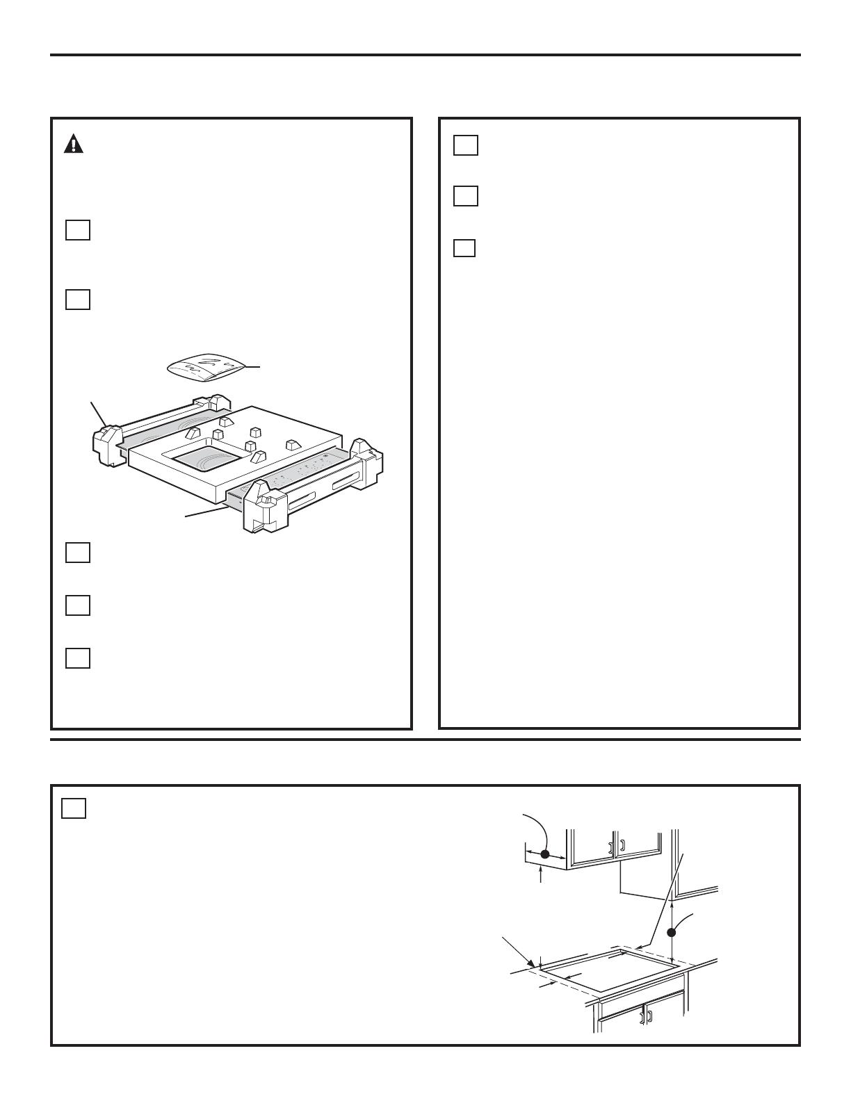
1
The following MINIMUM clearance dimensions
must be maintained.
PREPARING THE OPENING
If a 30" clearance between the cooking surface and
overhead combustible materials or metal cabinets
cannot be maintained, a minimum clearance of 24"
is required and the underside of the cabinets above
the cooktop must be protected with not less than 1/4"
insulating millboard covered with sheet metal not less
than 0.0122" thick.
13" MAX. Depth of unprotected
overhead cabinets
30" MIN.
Clearance from
countertop to
unprotected
overhead
surface
2" MIN. Clearance
from cutout to side
wall on the left of
the unit
15" MIN. Height
from countertop to
nearest cabinet on
either side of unit
1-1/2" MIN.
Clearance from
cutout to side wall
on the right of the
unit
ON
H
OT
Cooktop
Foam
Packaging
Literature Package
(Located under unit)
See label
next to
nameplate
for
minimum
clearance
to wall.


