Page is loading ...

Electric Cooktop
Installation manual
NZ24T4360RK
Install_NZ24T4360RK_EN.indd 1 2020-06-18 12:05:33

2 English
Contents
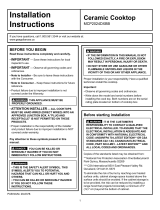
Contents Important safety information
For your safety
• For Personal Safety, remove house fuse or open circuit breaker before beginning
installation.
Failure to do so could result in serious injury or death.
• Be sure your cooktop is installed properly by a qualied installer or service
technician.
• To eliminate the risk of burns or re due to reaching over heated surface
elements, cabinet storage located above the surface units should be avoided.
If cabinet storage space is necessary, the risk can be reduced by installing a
range hood that projects horizontally a minimum of 5" beyond the bottom of the
cabinets. Cabinet installation above the cooktop may be no deeper than 13".
• Make sure the cabinets and wall coverings around the cooktop can withstand the
temperatures (up to 194 °F) generated by the cooktop.
• The cooktop should be easy to reach and illuminated by natural light during the
day.
• Always disconnect the electrical service to the cooktop before repairing or
servicing the cooktop. This can be done by disconnecting the fuse or circuit
breaker. Failure to do this could result in a dangerous or fatal shock. Know where
your main disconnect switch is located. If you do not know, have your electrician
show you.
Contents
Important safety information 2
Installation requirements 3
Tool and parts 3
Location requirements 4
Product dimensions 4
Electrical requirements 6
Installation instructions 7
Install cooktop 7
Make electrical connection 8
Complete installation 10
Install_NZ24T4360RK_EN.indd 2 2020-06-18 12:05:33

English 3
Important safety information
For your Safety
This appliance must be supplied with the proper voltage and frequency, and
connected to an individual, properly grounded branch circuit.
We recommend you have the electrical wiring and hookup of your cooktop
connected by a qualied electrician. After installation, have the electrician show
you where your main cooktop disconnect is located.
The cooktop conduit wiring is approved for copper wire connection only, and if
you have aluminum house wiring, you must use special UL approved connectors
for joining copper to aluminum.
WARNING
If the information in this manual is not followed exactly, a re or electrical shock
may result causing property damage, personal injury, or death.
WARNING
Before beginning the installation, switch the power off at the service panel and
lock the service disconnecting switch to prevent power from being switched on
accidentally. When the service disconnecting switch cannot be locked, securely
fasten a prominent warning device, such as a tag, to the service panel.
WARNING
This appliance must be properly grounded.
Installation requirements
Tool and parts
Tools you will need
Pencil Phillips Head Screwdriver Ruler or Straightedge
Safety Glasses Saber Saw ⅛" Drill Bit & Electric or
Hand Drill
Parts needed
• A UL listed or CSA approved connector for ½" (1.3 cm) diameter conduit
• UL listed wire connectors
Check local codes. Check existing electrical supply. See the “Electrical
requirements” section.
It is recommened that all electrical connections be made by a licensed, qualied
electrical installer.
Parts included
6 screw
(M4L10 2 ea,
M4L16 2 ea,
M4L75 2 ea)
Bracket Guide: 2 ea
Install_NZ24T4360RK_EN.indd 3 2020-06-18 12:05:33

4 English
Installation requirements
Installation requirements
Product dimensions
A
B
D
C
E
G
F
Cabinet Dimension
A Frame Depth 20⁄
1" (520 mm)
B Frame Width 23⅝" (600 mm)
C Case Depth 18⁄
1" (468 mm)
D Case Width 21⁄
1" (548 mm)
E Conduit Case Height 3⅜" (86 mm)
F Case Height 2⅜" (60 mm)
G Conduit Height 1" (26 mm)
Location requirements
IMPORTANT: Observe all governing codes and ordinances.
• Cabinet opening dimensions that are shown must be used.
Recessed installation area must provide complete enclosure around the
recessed portion of the cooktop.
• Grounded electrical supply is required. See “Electrical Requirements” section.
NOTE
It is recommended to install the Junction box on right side of the cabinet.
If installing the junction box near the left side, make sure the junction box does
not interfere with the cooktop (by concealing the junction box inside the wall).
IMPORTANT: To avoid damage to your cabinets, check with your builder or
cabinet supplier to make sure that the materials used will not discolor, delaminate
or sustain other damage. This cooktop has been designed in accordance with
the requirements of UL and CSA International and complies with the maximum
allowable wood cabinet temperatures of 194 °F (90 °C).
Install_NZ24T4360RK_EN.indd 4 2020-06-18 12:05:33

English 5
Installation requirements
Single Oven Under counter
D
A
F
E
B
G
C
H
01
02
01 See manual of built-in oven installation
for complete installation instructions.
See label on top of approved built-in
oven models.
02 Refer installation Manual of oven.
Dimension
A Minimum 3¾" (95 mm)
B 4" (101 mm)
C Minimum 22⁄" / Maximum 22¼" (Minimum 560 mm / Maximum 565 mm)
D Minimum 1"/ Maximum 1¼" (Minimum 25 mm / Maximum 32 mm)
E Minimum 23¼"/ Maximum 23½" (Minimum 590 mm / Maximum 596 mm)
F 22¼" (565 mm)
G Minimum 22¼" (Minimum 565 mm)
H Maximum 9½" (Maximum 241 mm) – Junction Box
IMPORTANT:
If installing a range hood or microwave hood combination above the cooktop,
follow the range hood or microwave hood combination installation instructions for
dimensions and clearance above the cooktop surface.
C
B
D
E
A
E
G
H
F
Cooktop
Back wall
Worktop
Junction box
Minimum distance from
ammable sidewalls
on top of the worktop
(both directions)
Dimension
A 22" - 22⅛" (558 mm - 562 mm)
B
18
⁄
" - 19" (478 mm - 482 mm)
C Cut area and backwall of Cooktop – minimum 1⅛" (28 mm)
D Front edge of cut area and front edge of worktop – minimum 1½" (38 mm)
E Flammable surface closest to the Cooktop (left/right) – minimum 1" (26 mm)
F Junction box or outlet from cabinet right – maximum 10" (254 mm)
G Junction box or outlet from cabinet bottom - minimum Junction box or outlet
15" (381 mm)
H Insulating board 2" (50.9 mm) mininum from bottom of Cooktop
Install_NZ24T4360RK_EN.indd 5 2020-06-18 12:05:34

6 English
Installation requirements
Installation requirements
Min 30"
Make sure the wall coverings, countertop
and cabinets around the cooktop can
withstand heat (up to 194 °F) generated by
cooktop.
NOTE
If cabinet has a drawer, a minimum 127 mm (5") depth clearance from the bottom
of cooktop to top of the drawer (or other obstruction) in base cabinet is required.
IMPORTANT:
The junction box must be located where it will allow considerable slack in the
conduit for serviceability.
Electrical requirements
WARNING
Electrical Shock Hazard
Disconnect power before servicing.
Use 8 gauge solid copper wire.
Electrically ground cooktop.
Label
Refer to the label on the bottom of
the cooktop for power requirements
and model information.
Failure to follow these instructions can
result in death, re, or electrical shock.
If codes permit and a separate ground
wire is used, it is recommended that a
qualied electrical installer determine that
the ground path and the wire gauge are in
accordance with local codes.
Check with a qualied electrical installer if
you are not sure the cooktop is properly
grounded.
This cooktop must be connected to a grounded metal, permanent wiring system.
Be sure that the electrical connection and wire size are adequate and in
conformance with the National Electrical Code, ANSI/NFPA 70-latest edition or CSA
Standards C22.
1-94, Canadian Electrical Code, Part 1 and C22.2 No. O-M91-latest edition, and all
local codes and ordinances.
A copy of the above code standards can be obtained from:
National Fire Protection Association
1 Batterymarch Park
Quincy, MA 02169-7471
CSA International
8501 East Pleasant Valley Road
Cleveland, OH 44131-5575
Install_NZ24T4360RK_EN.indd 6 2020-06-18 12:05:34

English 7
Installation instructions
Before you make the electrical connection:
To properly install your cooktop, you must determine the type of electrical
connection you will be using and follow the instructions provided for it here.
• A 3-wire or 4-wire, single phase, 208 or 240 volt AC, 60-Hz, power supply is
required on a dedicated double pole circuit breaker of at least 30 amps.
NOTE
• The cooktop is rated 240 volt. Some models have a neutral (white) wire.
• The cooktop should be connected directly to the junction box through exible,
armored or nonmetallic sheathed, copper cable. The exible, armored cable
extending from the fuse box or circuit breaker box should be connected directly
to the junction box.
• Locate the junction box to allow as much slack as possible between the junction
box and the cooktop so that the cooktop can be moved if servicing becomes
necessarry in the future.
• Do not cut the conduit. Use the length of conduit provided.
• A UL listed or CSA approved conduit connector is necessary at each end of the
power supply cable (at the cooktop and at the junction box). A listed conduit
connector is already provided at the cooktop.
• If the house has aluminum wiring, follow the procedure below:
1. Connect a section of solid copper wire to the pigtail leads.
2. Connect the aluminum wiring to the added section of copper wire using
special connectors and/or tools designed and UL listed for joining copper
to aluminum.
Follow the electrical connector manufacturer’s recommended procedure.
Aluminum/copper connection must conform with local codes and industry
accepted wiring practices.
Installation instructions
Install cooktop
STEP 1 Place cooktop
Cooktop
Insert the cooktop centerd into the cutout
opening. Make sure the cooktop is parallel
to the front edge of the countertop. Make
nal check that all required clearances are
met.
Install_NZ24T4360RK_EN.indd 7 2020-06-18 12:05:34

8 English
Installation instructions
Installation instructions
Make electrical connection
This cooktop is manufactured with ground wire (bare or green) connected to the
cooktop frame. Connect the cooktop cable to the junction box through the UL
listed or CSA approved conduit connector.
Electrical Connection Options
If your home has: And you will be connecting to : Go to section:
4-wire direct
A fused disconnect or circuit
breaker box
4-Wire Cable from Power
supply to 3-Wire Cable
from Cooktop
3-wire direct
A fused disconnect or circuit
breaker box
3-Wire Cable from Power
supply to 3-Wire Cable
from Cooktop
STEP 2-1 Installing the bracket guide
The bracket Guide can be installed after cooktop is placed into the cutout.
Bottom of Cooktop
M4L10
screw
M4L16 screw
1. On the bottom of the cooktop, nd the
holes where the bracket guide attaches.
(Refer to the gure.)
2. Place the bracket guide onto the hole,
and then move it towards the sidewall
of the cabinet until it touches the
sidewall.
3. Use the screws to fasten the bracket
guide to the cooktop and the sidewall.
NOTE
• Make sure you attach the bracket guides
on the left and right side.
• Make sure that the front edge of the
cooktop is parallel to the front edge of the
countertop. If repositioning is needed, lift
entire cooktop up from cutout to avoid
scratching the countertop.
STEP 2-2 Alternative Bracket Guide Installing
Countertop
Cooktop
M4L75 screw
M4L10 screw
1. Attach bracket guide to bottom and
select bracket location.
2. Tighten screw bracket guide to base of
cooktop.
3. Install M4L75 screw until bracket
touches the bottom of the countertop.
Install_NZ24T4360RK_EN.indd 8 2020-06-18 12:05:34

English 9
Installation instructions
3-Wire Cable from Power Supply to 3-Wire Cable from Cooktop
IMPORTANT: Where local codes permit, 3-wire cable can be use to supply power.
In those cases connect connect cooktop ground wire to the neutral wire from the
junction box.
A
B
C
D
E
F
G
H
I
A. 3-wire cable from power
supply
B. L1 wires
C. Ground (G) or bare ground
wire (from cooktop)
D. 3-wire cable from cooktop
E. Junction box
F. Neutral wire (from power
supply)
G. UL listed wire connector
H. L2 wires
I. UL listed or CSA approved
conduit connector
1. Disconnect power.
2. Remove Junction box cover, if present.
3. Connect the exible cable condult from
the cooktop to the junction box using
a UL listed or CSA approved condult
connector.
4. Tighten screws on condult connector, if
present.
5. Connect the two L2 wires together using
the UL listed wire connectors.
6. Connect the two L1 wires together using
the UL listed wire connectors.
7. Connect the Ground (G) or bare ground
wire from the cooktop cable to the
Ground (G) or bare ground wire (in the
junction box) using a UL listed wire
connectors.
8. Install junction box cover.
9. Reconnect power.
4-Wire Cable from Power Supply to 3-Wire Cable from Cooktop
IMPORTANT: Use the 4-wire cable from power supply where local codes do not
permit connecting the frame-ground conductor to the Neutral (N) junction box
wire.
A
B
C
D
E
G
H
I
F
A. 4-wire cable from power
supply
B. L1 wires
C. Ground (G) or bare ground
wire (from cooktop)
D. 3-wire cable from cooktop
E. Junction box
F. Neutral wire (from power
supply)
G. UL listed wire connector
H. L2 wires
I. UL listed or CSA approved
conduit connector
1. Disconnect power.
2. Remove Junction box cover if present.
3. Connect the exible cable condult from
the cooktop to the junction box using
a UL listed or CSA approved condult
connector.
4. Tighten screws on condult connector, if
present.
5. Connect the two L2 wires together using
the UL listed wire connectors.
6. Connect the two L1 wires together using
the UL listed wire connectors.
7. Connect the Ground (G) or bare ground
wire from the cooktop cable to the
Ground (G) or bare ground wire (in the
junction box) using a UL listed wire
connectors.
8. Put a UL listed wire connector on the
end of the Neutral wire.
9. Install junction box cover.
10. Reconnect power.
NOTE
• Usually L1 is Black, L2 is Red, Ground (G) is Green or bare wire and Neutral (N) is
White wire.
• Do not connect the bare ground wire to the Neutral (N) wire in the junction box.
Install_NZ24T4360RK_EN.indd 9 2020-06-18 12:05:34

10 English
Installation instructions
Installation instructions
Complete installation
1. Check that all parts are now installed. If there are any extra parts go back
through the steps to see if any steps were skipped..
2. Check that you have all of your tools.
3. Dispose of/recycle all packaging materials.
4. Use a mild solution or liquid household cleaner and warm water to clean
cooktop before use. Dry throughly with a soft cloth. For more information, see
the User’s Manual.
5. Reconnect power.
If You Need Assistance or Service:
Please reference the “User Manual” or contact the dealer from whom cooktop was
purchased.
Memo
Install_NZ24T4360RK_EN.indd 10 2020-06-18 12:05:34

Memo
Install_NZ24T4360RK_EN.indd 11 2020-06-18 12:05:34

QUESTIONS OR COMMENTS?
COUNTRY CALL OR VISIT US ONLINE AT
U.S.A
Consumer Electronics
1-800-SAMSUNG (726-7864) www.samsung.com/us/support
CANADA 1-800-SAMSUNG (726-7864)
www.samsung.com/ca/support (English)
www.samsung.com/ca_fr/support (French)
Scan the QR code* or visit
www.samsung.com/spsn
to view our helpful
How-to Videos and Live Shows
* Requires reader to be installed on your
smartphone
Install_NZ24T4360RK_EN.indd 12 2020-06-18 12:05:34

Placa de cocción eléctrica
Manual de instalación
NZ24T4360RK
Install_NZ24T4360RK_MES.indd 1 2020-06-18 12:05:27

2 Español
Contenido
Contenido Información importante de seguridad
Para su seguridad
• Para su seguridad personal, quite el fusible de su casa o corte la electricidad con el disyuntor antes
de comenzar la instalación.
No hacerlo podría causar lesiones graves o incluso la muerte.
• Asegúrese de que la placa de cocción sea correctamente instalada por un técnico de servicio o un
instalador calicado.
• Para eliminar el riesgo de quemaduras o incendios debido al contacto con los elementos calientes
de la supercie, se debería evitar colocar gabinetes de almacenamiento encima de las unidades
de la supercie. Si se necesita espacio de almacenamiento en gabinetes, el riesgo puede reducirse
instalando una campana para estufas que se proyecte horizontalmente por lo menos 5" más allá de
la parte inferior de los gabinetes. La profundidad de instalación de los gabinetes sobre la placa de
cocción no puede superar las 13".
• Asegúrese de que los gabinetes y los revestimientos de las paredes alrededor de la placa de
cocción puedan soportar las temperaturas (hasta 194 °F) que esta genera.
• La placa de cocción debe ser de fácil acceso y estar iluminada por la luz natural durante el día.
• Siempre desconecte el servicio eléctrico a la placa de cocción antes de realizar tareas de
reparación o mantenimiento. Esto puede hacerse al desconectar el fusible o disyuntor. No hacerlo
puede provocar una descarga eléctrica peligrosa o fatal. Es necesario que sepa dónde se encuentra
su interruptor de desconexión principal. Si no lo sabe, pida a su electricista que se lo muestre.
Contenido
Información importante de seguridad 2
Requisitos de instalación 3
Herramientas y piezas 3
Requisitos de ubicación 4
Dimensiones del producto 4
Requisitos eléctricos 6
Instrucciones de instalación 7
Instalación de la placa de cocción 7
Conexión eléctrica 8
Completar la instalación 10
Install_NZ24T4360RK_MES.indd 2 2020-06-18 12:05:27

Español 3
Información importante de seguridad
Para su seguridad
Este electrodoméstico debe ser alimentado con el voltaje y la frecuencia correctos, y debe
conectarse a un ramal de circuito individual correctamente conectado a tierra.
Le recomendamos que el cableado y la conexión de su placa de cocción sean realizados por un
electricista calicado. Luego de la instalación, solicítele al electricista que le muestre dónde se
encuentra el dispositivo de desconexión principal de la placa de cocción.
El cableado conductor de la placa de cocción está aprobado para la conexión de cables de cobre
solamente y si usted tiene un cableado de aluminio en el hogar, debe utilizar conectores especiales
aprobados por UL para unir cobre con aluminio.
ADVERTENCIA
Si la información de este manual no es seguida con exactitud, se podrían producir incendios o
descargas eléctricas que causen daños a la propiedad, lesiones personales o la muerte.
ADVERTENCIA
Antes de comenzar la instalación, corte la alimentación eléctrica desde el panel de servicio y
cierre con llave el interruptor de desconexión del servicio para evitar que la corriente eléctrica sea
conectada accidentalmente. Cuando el interruptor de desconexión del servicio no se pueda bloquear,
coloque un dispositivo de advertencia prominente, tal como una etiqueta, en el panel de servicio.
ADVERTENCIA
Este electrodoméstico debe conectarse a tierra correctamente.
Requisitos de instalación
Herramientas y piezas
Herramientas necesarias
Lápiz Destornillador Phillips Regla
Lentes de seguridad Sierra de sable Broca de ⅛” y taladro eléctrico
o manual
Piezas necesarias
• Un conector aprobado por UL o CSA para conductos con un diámetro de ½" (1.3 cm)
• Conectores de cable aprobados por UL
Consulte los códigos locales. Compruebe el suministro eléctrico existente. Consulte la sección
“Requisitos eléctricos”.
Se recomienda que todas las conexiones eléctricas sean realizadas por un electricista autorizado y
cualicado.
Piezas incluidas
6 tornillos
(M4L10 2 uds.,
M4L16 2 uds.,
M4L75 2 uds.)
Guía del soporte: 2 uds.
Install_NZ24T4360RK_MES.indd 3 2020-06-18 12:05:27

4 Español
Requisitos de instalación
Requisitos de instalación
Dimensiones del producto
A
B
D
C
E
G
F
Gabinete Dimensiones
A Profundidad del marco 20⁄
1" (520 mm)
B Ancho del marco 23⅝" (600 mm)
C Profundidad de la caja 18⁄
1" (468 mm)
D Ancho de la caja 21⁄
1" (548 mm)
E Altura de la caja del conducto 3⅜" (86 mm)
F Altura de la caja 2⅜" (60 mm)
G Altura del conducto 1" (26 mm)
Requisitos de ubicación
IMPORTANTE: Cumpla todos los códigos y ordenanzas exigidos por las autoridades pertinentes.
• Se deben utilizar las dimensiones de abertura de los gabinetes que se muestran.
El área de instalación empotrada debe proveer un recinto cerrado alrededor de la porción
empotrada de la placa de cocción.
• Se requiere un suministro eléctrico con conexión a tierra. Consulte la sección “Requisitos
eléctricos”.
NOTA
Se recomienda instalar la caja de empalmes en el lado derecho del gabinete.
Si instala la caja de empalmes cerca del lado izquierdo, asegúrese de que no interera con la placa
de cocción (ocultando la caja de empalmes dentro de la pared).
IMPORTANTE: Para evitar dañar sus gabinetes, verique con el constructor o distribuidor de
gabinetes para asegurarse de que los materiales utilizados no se descoloren, se descascaren o
puedan sufrir otros daños. Esta placa de cocción ha sido diseñada de acuerdo con los requisitos
de UL y CSA International, y cumple con las temperaturas para gabinetes de madera máximas
permitidas de 194 °F (90 °C).
Install_NZ24T4360RK_MES.indd 4 2020-06-18 12:05:27

Español 5
Requisitos de instalación
Horno simple bajo mostrador
D
A
F
E
B
G
C
H
01
02
01 Consulte el manual de instalación del horno
empotrado para obtener instrucciones de
instalación completas. Consulte la etiqueta
en la parte superior de los modelos de horno
empotrado aprobados.
02 Consulte el manual de instalación del horno.
Dimensiones
A Mínimo 3¾" (95 mm)
B 4" (101 mm)
C Mínimo 22⁄" / Máximo 22¼" (Mínimo 560 mm / Máximo 565 mm)
D Mínimo 1"/ Máximo 1¼" (Mínimo 25 mm / Máximo 32 mm)
E Mínimo 23¼"/ Máximo 23½" (Mínimo 590 mm / Máximo 596 mm)
F 22¼" (565 mm)
G Mínimo 22¼" (Mínimo 565 mm)
H Máximo 9½" (Máximo 241 mm) – Caja de empalmes
IMPORTANTE:
Si va a instalar una combinación de campana para estufa o campana para microondas sobre la placa
de cocción, siga las instrucciones de instalación de dichas campanas para conocer las dimensiones y
el espacio libre por encima de la supercie de la placa de cocción.
C
B
D
E
A
E
G
H
F
Cubierta
Pared trasera
Mesada
Caja de empalmes
Distancia mínima desde las
paredes laterales inamables
sobre la mesada (en ambas
direcciones)
Dimensiones
A 22" - 22⅛" (558 mm - 562 mm)
B 18⁄" - 19" (478 mm - 482 mm)
C Área de corte y pared posterior de la placa de cocción – mínimo 1⅛" (28 mm)
D Borde frontal del área de corte y borde frontal de la mesada – mínimo 1½" (38 mm)
E Supercie inamable más cercana a la cubierta (izquierda/derecha) – mínimo 1" (26 mm)
F Caja de empalmes o salida del gabinete derecha – máximo 10" (254 mm)
G Caja de empalmes o salida de la parte inferior del gabinete – máximo 15" (381 mm)
H Panel aislante 2" (50.9 mm) como mínimo de la parte inferior de la placa de cocción
Install_NZ24T4360RK_MES.indd 5 2020-06-18 12:05:28

6 Español
Requisitos de instalación
Requisitos de instalación
30” mín.
Asegúrese de que los revestimientos de las paredes,
el mostrador y los gabinetes alrededor de la placa de
cocción puedan soportar el calor (hasta 194 °F) que
esta genera.
NOTA
Si el gabinete tiene un cajón, se requiere un espacio de 127 mm (5") de profundidad como mínimo
desde la parte inferior de la placa de cocción hasta la parte superior del cajón (u otra obstrucción) en
la base del gabinete.
IMPORTANTE:
La caja de empalmes debe estar ubicada en un lugar donde haya una considerable holgura en el
conducto para realizar las tareas de servicio.
Requisitos eléctricos
ADVERTENCIA
Peligro de descarga eléctrica
Desconecte la alimentación antes de realizar tareas de mantenimiento o reparación.
Utilice un cable de cobre macizo calibre 8.
Realice la conexión eléctrica a tierra de la placa de cocción.
Etiqueta
Consulte la etiqueta en la parte inferior
de la placa de cocción para conocer los
requisitos de energía y la información del
modelo.
No seguir estas instrucciones puede provocar la
muerte, un incendio o una descarga eléctrica.
Si los códigos lo permiten y se emplea un cable a
tierra separado, es recomendable que un electricista
calicado determine si la trayectoria a tierra y el
calibre del cable cumplen con los códigos locales.
Si no está seguro si la conexión a tierra de la placa de
cocción está correctamente realizada, consulte a un
electricista calicado.
Esta placa de cocción debe conectarse a un sistema de conexión a tierra permanente de metal.
Asegúrese de que la conexión eléctrica y el tamaño del cable sean adecuados y que cumplan con la
versión más reciente del Código eléctrico nacional ANSI/NFPA 70 o la norma C22 de CSA.
1-94, la versión más reciente del Código eléctrico de Canadá, Sección 1 y C22.2 No. O-M91, y todos
los códigos y ordenanzas locales.
Se puede obtener una copia de las normas mencionadas arriba en:
National Fire Protection Association
1 Batterymarch Park
Quincy, MA 02169-7471
CSA International
8501 East Pleasant Valley Road
Cleveland, OH 44131-5575
Install_NZ24T4360RK_MES.indd 6 2020-06-18 12:05:28

Español 7
Instrucciones de instalación
Antes de realizar la conexión eléctrica:
Para instalar correctamente la placa de cocción, se debe determinar el tipo de conexión eléctrica que
se va a usar y seguir las instrucciones proporcionadas aquí.
• Se requiere un suministro de energía de 3 o 4 conductores, monofásico, con 208 o 240 voltios de
CA, 60 Hz, en un interruptor de doble polo dedicado de por lo menos 30 amperios.
NOTA
• La placa de cocción tiene una clasicación de 240 voltios. Algunos modelos disponen de un cable
neutro (blanco).
• La placa de cocción debe estar conectada directamente a la caja de empalmes a través de un cable
de cobre exible, blindado o con revestimiento no metálico. El cable blindado exible que se
extiende desde la caja del disyuntor o la caja de fusibles debe conectarse directamente a la caja de
empalmes.
• Ubique la caja de empalmes de modo tal que se permita la mayor holgura posible entre dicha caja
y la placa de cocción para que pueda moverse fácilmente en caso de que sea necesario realizar
tareas de servicio.
• No corte el conducto. Utilice la longitud del conducto proporcionada.
• Se requiere un conector de conductos aprobado por UL o CSA en cada extremo del cable de
alimentación (en la placa de cocción y en la caja de empalmes). Se proporciona un conector de
conductos aprobado con la placa de cocción.
• Si la casa tiene un cableado de aluminio, siga el procedimiento a continuación:
1. Conecte un tramo de cable de cobre macizo a los conductores de coleta.
2. Conecte el cableado de aluminio a la sección añadida de cable de cobre utilizando
conectores especiales y/o herramientas diseñadas para unir cobre con aluminio
aprobadas por UL.
Siga el procedimiento recomendado por el fabricante del conector eléctrico. La conexión entre
aluminio y cobre debe cumplir con los códigos locales y las prácticas de cableado aceptadas por
la industria.
Instrucciones de instalación
Instalación de la placa de cocción
PASO 1 Ubicación de la placa de cocción
Cubierta
Inserte la placa de cocción centrada en la abertura
cortada. Asegúrese de que la placa de cocción quede
paralela al borde delantero del mostrador. Haga una
vericación nal de que se hayan cumplido todas las
separaciones requeridas.
Install_NZ24T4360RK_MES.indd 7 2020-06-18 12:05:28

8 Español
Instrucciones de instalación
Instrucciones de instalación
Conexión eléctrica
La placa de cocción está fabricada con un cable a tierra (desnudo o verde) conectado a su marco.
Conecte el cable de la placa de cocción a la caja de empalmes a través de un conector de conductos
aprobado por UL o CSA.
Opciones de conexión eléctrica
Si en su casa tiene: Y se conectará a: Vaya a la sección:
4 conectores, directo
Una caja de desconexión con fusibles
o disyuntor
Cable de 4 conductores del
suministro eléctrico al cable de
3 conductores de la placa de
cocción
3 conectores, directo
Una caja de desconexión con fusibles
o disyuntor
Cable de 3 conductores del
suministro eléctrico al cable de
3 conductores de la placa de
cocción
PASO 2-1 Instalación de la guía del soporte
La guía del soporte se puede instalar después de haber colocado la placa de cocción dentro de la
abertura recortada.
Parte inferior de la placa de cocción
Tornillo
M4L10
Tornillo M4L16
1. Ubique los oricios donde se ja la guía del
soporte en la parte inferior de la placa de
cocción. (Consulte la imagen).
2. Coloque la guía del soporte en el oricio y, luego,
muévala hacia la pared lateral del gabinete hasta
que la toque.
3. Ajuste la guía del soporte a la placa de cocción y
la pared lateral con los tornillos.
NOTA
• Asegúrese de jar las guías del soporte del lado
izquierdo y derecho.
• Asegúrese de que el borde delantero de la placa
de cocción quede paralelo al borde delantero del
mostrador. Si se necesita un reposicionamiento,
levante y retire la placa de cocción completa de la
abertura recortada para evitar rayar el mostrador.
PASO 2-2 Instalación de la guía del soporte alternativa
Mesada
Placa de cocción
Tornillo M4L75
Tornillo M4L10
1. Fije la guía del soporte a la parte inferior y
seleccione la ubicación del soporte.
2. Apriete el tornillo de la guía del soporte a la base
de la placa de cocción.
3. Instale el tornillo M4L75 hasta que el soporte
toque la parte inferior de la mesada.
Install_NZ24T4360RK_MES.indd 8 2020-06-18 12:05:28
/