Page is loading ...

Contractor: Read these
instructions before installing or
servicing humidier.
Installation
Instructions
for Models 2000, 2100,
2001 and 2101
High-Capacity Bypass
Flow-Thru Humidiers
with Side Entry
Inside Front Cover
©Skuttle Mfg. Co. 2008 000-0756-336 E-Web 9/08 (for English)

Contents
Warnings and Cautions (Please read) ...................................................................................... Below
Humidier Placement ....................................................................................................................... 1
Step-by-Step Installation Instructions ............................................................................................... 2
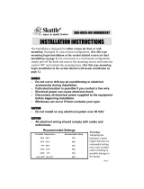
Warnings and Cautions
WARNING: This high-capacity ow-thru humidier must be installed by a
qualied heating and air conditioning contractor. Failure to comply could result
in serious injury from electrical shock, damage humidier or heating appliance,
and/or void all warranties.
!
ADDITIONAL WARNINGS:
Disconnect electrical power to the
furnace before starting installation to avoid
serious injury or electrocution.
Use care when cutting plenum
openings and handling ductwork. Sharp
edges may cause serious injury.
Do not cut or drill any air conditioning
or electrical accessories during
humidier installation. (See “Placement”
diagrams, page 1.) Electrocution is
possible if you come in contact with a
live electrical wire; blindness can occur if
refrigerant contacts your eyes.
CAUTIONS:
Do not install the unit where freezing
temperatures could occur, or where
temperatures could exceed 180°F
(82.22°C).
Do not install the unit on a furnace jacket.
1.
2.
3.
1.
2.
Do not install the unit on a plenum face
where the blanked-off ends of the cooling
coil restrict air movement through the
humidifier.
Do not set humidity higher than recom-
mended. Condensation damage may
result.
Do not set humidity up to recommended
levels if there is condensation on the inside
windows of any living space. Condensation
damage may result.
Do not install the unit on any plenum
where static pressure exceeds 0.4 in. (1.02
cm) W.C.
Do not install the unit where water
pressure exceeds 125 psi (861.85 kPa).
Leakage may result. Follow relevant codes
regarding pressure reduction.
Be sure that the installation, wiring and
plumbing on the humidifier comply with
local codes, ordinances and regulations.
3.
4.
5.
6.
7.
8.
Contractor Assistance:
Phone: 888-SKUTTLE (758-8853)
Email: [email protected]
Web: www.goskuttle.com
Skuttle and the “Happy House” character are registered trademarks
of Skuttle Mfg. Co. (DBA Skuttle Indoor Air Quality Products)

1
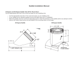
Explanation of A and B Options
Mounting the humidier on the warm air
supply or the cold air return plenum does
not alter humidier performance. In either
location, air will ow from the warm air to the
cold air side due to the positive and negative
pressures of the heating system.
Humidity produced by a bypass ow-thru
humidier is dispersed as a pure vapor (i.e., a
gas), not as a liquid. The moisture will remain
in the air, even when reheated. The humidity
can only be depleted by escaping to the
outside or by condensing on a cold surface.
Because all surfaces in the furnace/humidier
system are warm, condensation is unlikely.
Humidier Placement
Mounting Options
Placement: Skuttle
2000- and 2100-Series
Flow-Thru Humidiers
should be installed as
shown in relation to the
AC coils.
Option A: Mount
the humidier on
the warm air ple-
num. Connect the
unit to the cold air
return using 6 in.
(15.24 cm) round
duct. OR...
Option B: Mount
the humidier to
the cold air return.
Connect the unit to
the warm air return
using 6 in. (15.24
cm) round duct.
Step-by-Step Installation Instructions

2
Step-by-Step Installation Instructions
NOTE: Photos shown here and on the
following pages are of the Skuttle 2000/
2100 Flow-Thru Humidier. The 2001/2101
unit is somewhat larger, however, instal-
lation procedures for all four models are
identical unless otherwise noted.
3. Disengage the
humidier cover from
the mounting frame
by rotating the thumb
screw at the bottom
counterclockwise ().
4. Tilt and lift the cover
off the frame.
5. Pull out the drip tray
and evaporator pad
assembly by grasping
the top lip and tipping
out.
6. To convert the
humidier from right-
to left-side discharge,
apply pressure to the
inside of the side panel
using both hands. Lift.
Exchange the two side
pieces. Reinstall using
moderate pressure.
7. Place the mounting
frame into the plenum
opening so that the
frame hooks over the
bottom of the opening.
Screw the frame to the
plenum.
8. Stand the
evaporator pad
upright with the
index mark on top.
Make sure the wick
is seated securely in
the drip tray.
9. Place the drip
tray on top of the
pad. Reinstall the
evaporator pad and
drip tray.
1. Locate the 2000/
2100 or 2001/2101
mounting template in
the humidier carton.
Tape the template
lengthwise onto the
furnace plenum,
making sure it is
level.
2. Trace around the
template.* Remove the
template. Accurately
cut the plenum
opening.
*Models 2000 and 2100
cutout size is 9 in. (22.86
cm) wide by 10 in. (25.40
cm) long.
Models 2001 and 2101 cutout size is 10-5/8 in. (26.99
cm) wide by 16-5/8 in. (42.23 cm) wide.

3
10. Reattach the cover
assembly by hooking
it at the top of the
mounting frame, then
securing it with the
thumb screw at the
bottom.
11. Install the 6 in.
(15.24 cm) starting
collar on the opposite
plenum. Slip on a 90°
elbow and measure
the length of 6 in.
(15.24 cm) round duct required to make the
connection. Screw the 6 in. (15.24 cm) duct
to the discharge collar.
13. TO WIRE MODEL
2000 OR 2001 AND
THE HUMIDISTAT...
shut off the furnace
power. If the furnace is
relatively new, check
to see if there is an
electronic control board
with humidier control
terminals (sometimes
marked HUM). You
may also consult the furnace installation
manual or wiring diagram. If humidier ter-
minals are present, proceed to No. 13A.
If humidier terminals are not present,
answer the following questions:
Is the blower motor powered with a supply
greater than 120 volts?
•
OR
Does the blower motor change speed
when the thermostat’s system fan switch is
activated during the heating mode?
OR
Does the blower motor change speed
when the air conditioning is activated?
If the answer to ANY of the above is YES,
skip to No. 13B.
If the answer to ALL of the above ques-
tions is NO, skip to No. 13C.
13A. Using a meter, check the terminals for
power output during the heating cycle when
the blower is running. Determine the output
voltage. Some circuit boards have printed
indicators. Most are 24 volt AC and only
require connecting the humidier solenoid
and the humidistat. (See Wiring Diagram A,
below. )
(If, in rare cases, the furnace terminals are
120 volt, connect the transformer to the
terminals and wire as shown in Diagram C
on page 4. )
•
•
12. TO WIRE MODEL 2100 OR 2101 AND
THE COMPUSTAT...refer to the Safety and
Installation Instructions that come with the
Compustat automatic humidier control.
Wiring Diagram A
Terminals on Board
1
5
3
2
4
Diagram Key
Humidistat
24 Volt AC Humidistat Wiring
Humidier
Solenoid
24 Volt (HUM) Terminals on Furnace Board
1.
2.
3.
4.
5.

4
Step-by-Step Installation Instructions (cont’d.)
13C. If you determine that the system blower
motor is a 120 volt, single-speed motor, and
that it does not change speed during the
cooling mode, wire the transformer into the
blower motor wiring. This will coordinate
the humidier and system operations. (See
Wiring Diagram C, above right. )
13B. For multi-speed blowers or systems not
using 120 VAC, use an
A50 Electronic Relay
or other method of
coordinating humidier
operation with the
system air mover. The
source of power for the humidier transformer
should not be the blower motor wiring, but
an independent source. This is to prevent
transformer failure, either from feedback from
the blower motor during air conditioning,
or from voltage greater than the 120 volts
required for the transformer. (See Wiring
Diagram B, below. )
14. Tap into the water
supply line using the
saddle valve provided.
Follow the instructions
below....
Saddle Tapping
Valve Installation
Instructions
CAUTIONS (Failure
to heed the following
warnings may result in damage to the
piercing needle):
Do not turn the handle on the saddle
tapping valve until instructed to do so.
Do not allow the piercing needle to
protrude beyond the rubber gasket until
instructed to do so.
To Install the Saddle Valve on Copper
Tubing...
Assemble the saddle valve on the copper
tubing.
For 3/8 in. (0.95 cm) O.D. tubing, use
the bracket with side projections to
prevent distortion of the tubing.
Use the “V” side of the bracket for all
larger diameter tubing.
•
•
A.
•
•
Diagram B
Multi-Speed Blower
1
3
2
7
4
5
6
8
Diagram Key
Humidistat
24 Volt AC Humidistat Wiring
Humidier
Relay
Blower Motor
24 Volt AC Transformer
Solenoid
120 Volt AC Supply
1.
2.
3.
4.
5.
6.
7.
8.
Diagram Key
Humidistat
24 Volt AC Humidistat Wiring
Humidier
24 Volt AC Transformer
Solenoid
120 Volt AC Supply
1.
2.
3.
4.
5.
6.
Wiring Diagram C
Single-Speed Blower
1
3
2
5
4
6

5
Make sure the brackets are parallel, then
tighten the screws evenly and rmly.
Connect the water line to the saddle valve
outlet. Use the brass sleeve for 1/4 in.
(0.64 cm) copper tubing.
NOTE: A small amount of water will
escape from the outlet until the tubing is
fully pierced.
To pierce the tubing, turn the saddle valve
handle clockwise () until you feel it is
rmly seated.
Turn the handle counterclockwise () to
open the valve.
To Install the Saddle Valve on Steel or
Brass Pipe...
Turn off the water supply and drain the
line.
Using a hand drill, drill a 3/16 in. (0.48 cm)
hole in the pipe.
DANGER: Using an electric drill may
cause shock or electrocution.
Turn the saddle valve handle to expose the
needle beyond the rubber gasket no more
than 3/16 in. (0.48 cm).
Place the body of the saddle valve over the
hole so that the needle ts into the hole.
B.
C.
D.
E.
A.
B.
C.
D.
15. Connect copper tubing from the saddle
valve to the solenoid valve. (Do not use
plastic tubing.) Check
for leaks.
16. Attach a 1/2 in.
(1.27 cm) ID vinyl hose
and clamp to carry
the ushed water from
the unit to the drain. To avoid damage to
the drain tting, do not use solvent type
adhesives when connecting the plastic
hose to the humidier.
15
16
17. Finally, test
operation. Check
for water leaks. Be
sure the humidistat
(or Compustat) is
operating properly.
Tighten the bottom clamp evenly, making
sure that the brackets are parallel.
Turn the saddle valve handle clockwise ()
to close the valve.
Turn on the water supply. The saddle
tapping valve is now ready for operation.
F.
G.
H.

101 Margaret Street • Marietta, OH 45750
800-848-9786 • 740-373-9169
[email protected] • www.goskuttle.com
/